Text extracted from the exhibit documents filed with the FCC. Open a document above to read the original.
2348 Walsh Avenue Santa Clara, CA 95051 [email protected] www.everactive.com User’s Manual FCC warning: This device complies with Part 15 of the FCC Rules. Operation is subject to the following two conditions: (1) this device may not cause harmful interference, and (2) this device must accept any interference received, including interference that may cause undesired operation. Canada (IC) warning: Canada Low-power license-exempt radio communication devices (RSS-247) 1. Common information operation is subject to the following two conditions: a. This device may not cause interference, and b. This device must accept any interference, including interference that may cause undesired operation of the device 2. Informations communes Son fonctionnement est soumis aux deux conditions suivantes: a. Ce dispositive ne peut causer des interferences, et b. Ce dispositive doit accepter toute interference, y compris les interferences qui peuvent causer un mauvais fonctionnement du dispositive. RF Exposure and Separation Distance: For safe operation, the minimum separation distance should be 20cm. Pour un fonctionnement en toute sécurité, la distance de séparation minimale doit être de 20 cm. 2348 Walsh Avenue Santa Clara, CA 95051 [email protected] www.everactive.com Note: The Boomerang device is used internally for Everactive products and services – it is not sold separately to other customers. The following User’s Guide is an instruction set used to program and control Boomerang to prepare it for integration with Everactive products or troubleshooting. Hardware needs: 1. Wake-up dongle with programmed firmware image 2. Window 10 PC w/ USB port Connecting the DUT to your PC: Connect the DUT to a USB 3.0 port on your PC or a USB-powered HUB. A green LED will blink while the DUT establishes a COM port. The COM port can be found in the Device Manager under USB Serial Device. At this point you should be ready to run commands. Figure 1: Device Manager Operating the Wake-up Dongle using Python: Install the python package (internal to Everactive) - pip3 install -i http://python-registry.psikick.com --trusted-host python- registry.psikick.com wakeup_device Upgrade the wakeup-device package directly from the internal python registry 2348 Walsh Avenue Santa Clara, CA 95051 [email protected] www.everactive.com - pip3 install --upgrade -i http://python-registry.psikick.com --trusted-host python-registry.psikick.com wakeup_device Open a command line prompt to run commands to configure Boomerang Run wu_fcc --h to see configuration options Figure 2: List of configuration options Run the script starting with wu_fcc followed by the commands to program the transceiver. The wakeup.py script can operate the following functions: • Vary transmit output power • Hop across all channels • Sweep all channels • Specify channels • Receive packets Example: See configuration options: wu_fcc --h Example: Send a wake-up message: wu_fcc --search --wu --power 30 The LED on the wake-up dongle will light up when a transmission is successfully sent. See image below: Figure 3: CN Dongle operating (as seen via LED)
2348 Walsh Avenue Santa Clara, CA 95051 [email protected] www.everactive.com March 10, 2020 Federal Communications Commission Equipment Authorization branch 7435 Oakland Mills Road Columbia, MD 21046 To whom it may concern: I, the undersigned, hereby authorize UL Verification Services Inc. to act on our behalf in all manners relating to application for equipment authorization, including signing of all documents relating to these matters. Any and all acts carried out by UL Verification Services Inc. on our behalf shall have the same effect as acts of our own. I, the undersigned, hereby certify that we are not subject to a denial of federal benefits, that includes FCC benefits, pursuant to Section 5301 of the Anti-Drug Abuse Act of 1988, 21 U.S.C. 853(a). In authorizing UL Verification Services Inc. as our representative, we still recognize that we are responsible to: a) comply with the relevant provisions of the certification program; b) make all necessary arrangements for the conduct of the evaluation, including provision for examining documentation and access to all areas, records (including internal audit reports) and personnel for the purposes of evaluation (e.g. testing, inspection, assessment, surveillance, reassessment) and resoluti on of complaints; c) make claims regarding certification only in respect of the scope for which certification has been granted; d) do not use our product certification in such a manner as to bring the Certification Division into disrepute and not make any statement regarding our product certification which the Certification Division may consider misleading or unauthorized; e) upon suspension or cancellation of certification, discontinue use of all advertising matter that contai ns any reference thereto and return any certification documents as required by the Certification Division; f) use certification only to indicate the products are certified as being in conformity with specifie d standards; g) endeavor to ensure that no certificate or report nor any part thereof is used in a misleading manner; 2348 Walsh Avenue Santa Clara, CA 95051 [email protected] www.everactive.com h) ensure that any reference to our product certification in communication media such as documents, brochures or advertising, complies with the requirements of the Certification Division; i) keep a record of all complaints made known to the us relating to the product’s compliance wi th requirements of the relevant standard and to make these records available to the when requested; j) take appropriate action with respect to such complaints and any deficiencies found in products or services that affect compliance with the requirements for certification; k) document the actions taken. This authorization is valid until further written notice from the applicant. Sincerely Yours, David D. Wentzloff Everactive
Applicant/Grantee Everactive FCC ID: 2AO7C-83000001 Section 15.212 Modular Transmitters Request for Modular Approval Request for Limited Modular Approval Requirements EUT Conditions Comply (Y/N) Single Modular Approval Requirements 1 The radio elements of the modular transmitter must have their own shielding. The physical crystal and tuning capacitors may be located external to the shielded radio elements. RF shield covers STMicroelectronics S2-LP sub-GHz radio as well as Skyworks SE2435L_R RF front end. YES 2 The modular transmitter must have buffered modulation/data inputs (if such inputs are provided) to ensure that the module will comply with Part 15 requirements under conditions of excessive data rates or over-modulation. The module communicates over standard USB (Type A) at a speed of 12Mbps. YES 3 The modular transmitter must have its own power supply regulation. Power supply regulation via USB (5V) and then regulated by an LDO on the module YES 4 The modular transmitter must comply with the antenna and transmission system requirements of Sections 15.203, 15.204(b) and 15.204(c). The antenna must either be permanently attached or employ a “unique” antenna coupler (at all connections between the module and the antenna, including the cable). The “professional installation” provision of Section 15.203 is not applicable to modules but can apply to limited modular approvals under paragraph (b) of this section. This module is intended to be designed into a system within Everactive so no end customer will install the module with antenna on their own, nor have access to the module once deployed. YES 5 The modular transmitter must be tested in a stand-alone configuration, i.e., the module must not be inside another device during testing for compliance with Part 15 requirements. Unless the transmitter module will be battery powered, it must comply with the AC line conducted requirements found in Section 15.207. AC or DC power lines and data input/output lines connected to the module must not contain ferrites, unless they will be marketed with the module (see Section 15.27(a)). The length of these lines shall be the length typical of actual use or, if that length is unknown, at least 10 centimeters to insure that there is no coupling between EUT was tested outside any enclosure – it was connected to a laptop via USB YES the case of the module and supporting equipment. Any accessories, peripherals, or support equipment connected to the module during testing shall be unmodified and commercially available (see Section 15.31(i)). 6 The modular transmitter must be equipped with either a permanently affixed label or must be capable of electronically displaying its FCC identification number. (A) If using a permanently affixed label, the modular transmitter must be labeled with its own FCC identification number, and, if the FCC identification number is not visible when the module is installed inside another device, then the outside of the device into which the module is installed must also display a label referring to the enclosed module. This exterior label can use wording such as the following: “Contains Transmitter Module FCC ID: XYZMODEL1” or “Contains FCC ID: XYZMODEL1.” Any similar wording that expresses the same meaning may be used. The Grantee may either provide such a label, an example of which must be included in the application for equipment authorization, or, must provide adequate instructions along with the module which explain this requirement. In the latter case, a copy of these instructions must be included in the application for equipment authorization. (B) If the modular transmitter uses an electronic display of the FCC identification number, the information must be readily accessible and visible on the modular transmitter or on the device in which it is installed. If the module is installed inside another device, then the outside of the device into which the module is installed must display a label referring to the enclosed module. This exterior label can use wording such as the following: “Contains FCC certified transmitter module(s).” Any similar wording that expresses the same meaning may be used. The user manual must include instructions on how to access the electronic display. A copy of these instructions must be included in the application for equipment authorization. The FCC ID will be attached to the PCB either via silkscreen or a sticker. The additional information will be included in the user’s manual. YES 7 The modular transmitter must comply with any specific rules or operating requirements that ordinarily apply to a complete transmitter and the manufacturer must provide adequate instructions along with the module to explain any such requirements. A copy of these instructions must be included in the Everactive will control the entire installation process so a customer will not have to install this module themselves. To that end, any configuration information will be included in the user’s guide for the host product. YES application for equipment authorization. More information on the module install into the host can be provided at request. 8 The modular transmitter must comply with any applicable RF exposure requirements in its final configuration. RF exposure report is included. YES A limited modular approval may be granted for single or split modular transmitters that do not comply with all of the above requirements, e.g., shielding, minimum signaling amplitude, buffered modulation/data inputs, or power supply regulation, if the manufacturer can demonstrate by alternative means in the application for equipment authorization that the modular transmitter meets all the applicable Part 15 requirements under the operating conditions in which the transmitter will be used. Limited modular approval also may be granted in those instances where compliance with RF exposure rules is demonstrated only for particular product configurations. The applicant for certification must sta…
Text truncated - open the document above for the full version.
2348 Walsh Avenue Santa Clara, CA 95051 [email protected] www.everactive.com Proposed ID Label and Location for Module Proposed ID Label: Proposed Location Hardware FCC ID: 2AO7C-83000001 IC: 23743-83000001 Model: 830-00001 2348 Walsh Avenue Santa Clara, CA 95051 [email protected] www.everactive.com Proposed FCC ID Label for Host Device
NVLAP Lab code: 200065-0 TEST REPORT Report Number. : 13156692-E3V4 Applicant : EVERACTIVE 2986 OAKMEAD VILLAGE CT SANTA CLARA, CA 95051 U.S.A. Model : 830-00001 FCC ID : 2AO7C-83000001 ISED ID : 23743-83000001 EUT Description : 915MHz Transmitter Test Standard(s) : FCC Part 1 Subpart I FCC Part 2 Subpart J INDUSTRY CANADA RSS 102 ISSUE 5 Date Of Issue: June 25, 2020 Prepared by: UL Verification Services Inc. 47173 Benicia Street Fremont, CA 94538 U.S.A. TEL: (510) 771-1000 FAX: (510) 661-0888 REPORT NO: 13156692-E3V4 DATE: 6/25/2020 FCC ID: 2AO7C-83000001 ISED ID: 23743-83000001 Page 2 of 11 UL VERIFICATION SERVICES INC. FORM NO: CCSUP4701I 47173 BENICIA STREET, FREMONT, CA 94538, USA TEL: (510) 771-1000 FAX: (510) 661-0888 This report shall not be reproduced except in full, without the written approval of . UL Verification Services Inc. Revision History Rev. Issue Date Revisions Revised By V1 5/08/2020 Initial Issue - V2 5/22/2020 Report revised based on reviewer’s comments. Bobby Bayani V3 5/27/2020 Report revised based on reviewer’s comments. Sec. 2 updated. Bobby Bayani V4 6/24/2020 Report revised based on reviewer’s comments. Added FSK mode. Bobby Bayani REPORT NO: 13156692-E3V4 DATE: 6/25/2020 FCC ID: 2AO7C-83000001 ISED ID: 23743-83000001 Page 3 of 11 UL VERIFICATION SERVICES INC. FORM NO: CCSUP4701I 47173 BENICIA STREET, FREMONT, CA 94538, USA TEL: (510) 771-1000 FAX: (510) 661-0888 This report shall not be reproduced except in full, without the written approval of . UL Verification Services Inc. TABLE OF CONTENTS 1. ATTESTATION OF TEST RESULTS ................................................................................. 4 2. TEST METHODOLOGY ..................................................................................................... 5 3. REFERENCES ................................................................................................................... 5 4. FACILITIES AND ACCREDITATION ................................................................................. 5 5. MAXIMUM PERMISSIBLE RF EXPOSURE ....................................................................... 6 5.1. FCC RULES ................................................................................................................ 6 5.2. IC RULES .................................................................................................................... 7 5.3. EQUATIONS ................................................................................................................ 8 5.4. IC EXEMPTION ..........................................................................................................10 6. RF EXPOSURE RESULTS ................................................................................................11 REPORT NO: 13156692-E3V4 DATE: 6/25/2020 FCC ID: 2AO7C-83000001 ISED ID: 23743-83000001 Page 4 of 11 UL VERIFICATION SERVICES INC. FORM NO: CCSUP4701I 47173 BENICIA STREET, FREMONT, CA 94538, USA TEL: (510) 771-1000 FAX: (510) 661-0888 This report shall not be reproduced except in full, without the written approval of . UL Verification Services Inc. 1. ATTESTATION OF TEST RESULTS COMPANY NAME: EVERACTIVE 2986 OAKMEAD VILLAGE CT SANTA CLARA, CA 95051 U.S.A. EUT DESCRIPTION: 915 MHz Transmitter MODEL: 830-00001 APPLICABLE STANDARDS STANDARD TEST RESULTS FCC PART 1 SUBPART I & PART 2 SUBPART J Pass INDUSTRY CANADA RSS 102 ISSUE 5 Pass UL Verification Services Inc. tested the above equipment in accordance with the requirements set forth in the above standards. All indications of Pass/Fail in this report are opinions expressed by UL Verification Services Inc. based on interpretations and/or observations of test results. Measurement Uncertainties were not taken into account and are published for informational purposes only. The test results show that the equipment tested is capable of demonstrating compliance with the requirements as documented in this report. Note: The results documented in this report apply only to the tested sample, under the conditions and modes of operation as described herein. This document may not be altered or revised in any way unless done so by UL Verification Services Inc. and all revisions are duly noted in the revisions section. Any alteration of this document not carried out by UL Verification Services Inc. will constitute fraud and shall nullify the document. This report must not be used by the client to claim product certification, approval, or endorsement by NVLAP, NIST, any agency of the Federal Government, or any agency of the U.S. government. Approved & Released For UL Verification Services Inc. By: Calculated By: THU CHAN BOBBY BAYANI CONSUMER TECHNOLOGY DIVISION CONSUMER TECHNOLOGY DIVISION OPERATIONS LEADER LEAD PROJECT ENGINEER UL Verification Services Inc. UL Verification Services Inc REPORT NO: 13156692-E3V4 DATE: 6/25/2020 FCC ID: 2AO7C-83000001 ISED ID: 23743-83000001 Page 5 of 11 UL VERIFICATION SERVICES INC. FORM NO: CCSUP4701I 47173 BENICIA STREET, FREMONT, CA 94538, USA TEL: (510) 771-1000 FAX: (510) 661-0888 This report shall not be reproduced except in full, without the written approval of . UL Verification Services Inc. 2. TEST METHODOLOGY All calculations were made in accordance with the following: • KDB 447498 D01 • KDB 447498 D03 3. REFERENCES All measurements were made as documented in test report no. 13156692-E1V4. Duty cycle, Antenna gain, and output power data is excerpted from the applicable test reports. 4. FACILITIES AND ACCREDITATION The test sites and measurement facilities used to collect data are located at 47173 Benicia Street, Fremont, California, USA. UL Verification Services Inc. is accredited by NVLAP, Laboratory Code 200065-0. REPORT NO: 13156692-E3V4 DATE: 6/25/2020 FCC ID: 2AO7C-83000001 ISED ID: 23743-83000001 Page 6 of 11 UL VERIFICATION SERVICES INC. FORM NO: CCSUP4701I 47173 BENICIA STREET, FREMONT, CA 94538, USA TEL: (510) 771-1000 FAX: (510) 661-0888 This report shall not be reprodu…
Text truncated - open the document above for the full version.
NVLAP LAB CODE 200065-0 TEST REPORT Report Number: 13156692-E1V5 Applicant : EVERACTIVE 2986 OAKMEAD VILLAGE CT SANTA CLARA, CA 95051 U.S.A. Model : 830-00001 FCC ID : 2AO7C-83000001 ISED ID : 23743-83000001 EUT Description : 915MHz Transmitter Test Standard(s) : FCC 47 CFR ISED RSS-247 ISSUE 2 ISED RSS-GEN ISSUE 5 Date Of Issue: June 23, 2020 Prepared by: UL Verification Services Inc. 47173 Benicia Street Fremont, CA 94538, U.S.A. TEL: (510) 319-4000 FAX: (510) 661-0888 REPORT NO: 13156692-E1V5 DATE: 6/23/2020 FCC ID: 2AO7C-83000001 ISED ID: 23743-83000001 Page 2 of 137 UL VERIFICATION SERVICES INC. 47173 BENICIA STREET, FREMONT, CA 94538, USA TEL: (510) 771-1000 FAX: (510) 661-0888 This report shall not be reproduced except in full, without the written approval of UL Verification Services Inc. Revision History Rev. Issue Date Revisions Revised By V1 05/08/2020 Initial Issue --- V2 05/18/2020 Report revised based on reviewer’s comments. Bobby Bayani V3 05/22/2020 Section 2, revised RSS-GEN issue number Grace Rincand V4 05/28/2020 Report revised based on reviewer’s comments. Sec. 8.2 updated. Bobby Bayani V5 06/23/2020 Report revised based on reviewer’s comments. Additional testing performed for Mode 2. Bobby Bayani REPORT NO: 13156692-E1V5 DATE: 6/23/2020 FCC ID: 2AO7C-83000001 ISED ID: 23743-83000001 Page 3 of 137 UL VERIFICATION SERVICES INC. 47173 BENICIA STREET, FREMONT, CA 94538, USA TEL: (510) 771-1000 FAX: (510) 661-0888 This report shall not be reproduced except in full, without the written approval of UL Verification Services Inc. TABLE OF CONTENTS 1. ATTESTATION OF TEST RESULTS ................................................................................. 5 2. TEST METHODOLOGY ..................................................................................................... 7 3. FACILITIES AND ACCREDITATION ................................................................................. 7 4. DECISION RULES AND MEASUREMENT UNCERTAINTY .............................................. 8 4.1. METROLOGICAL TRACEABILITY .............................................................................. 8 4.2. DECISION RULES ....................................................................................................... 8 4.3. MEASUREMENT UNCERTAINTY ............................................................................... 8 4.4. SAMPLE CALCULATION ............................................................................................ 8 5. EQUIPMENT UNDER TEST ............................................................................................... 9 5.1. EUT DESCRIPTION .................................................................................................... 9 5.2. MAXIMUM OUTPUT POWER...................................................................................... 9 5.3. DESCRIPTION OF AVAILABLE ANTENNAS .............................................................. 9 5.4. SOFTWARE AND FIRMWARE .................................................................................... 9 5.5. WORST-CASE CONFIGURATION AND MODE .......................................................... 9 5.6. DESCRIPTION OF TEST SETUP ...............................................................................10 6. TEST AND MEASUREMENT EQUIPMENT ......................................................................13 7. MEASUREMENT METHODS ............................................................................................14 8. ANTENNA PORT TEST RESULTS ...................................................................................15 8.1. ON TIME AND DUTY CYCLE .....................................................................................15 8.1.1. MODE 1 - OOK ....................................................................................................15 8.1.2. MODE 2 - FSK .....................................................................................................16 8.2. 20 dB AND 99% BANDWIDTH ...................................................................................17 8.2.1. 99% OCCUPIED BANDWIDTH ...........................................................................18 8.2.1.1. MODE 1 - OOK ................................................................................................18 8.2.1.1. MODE 2 - FSK .................................................................................................19 8.2.2. 20dB BANDWIDTH ..............................................................................................20 8.2.2.1. MODE 1 - OOK ................................................................................................20 8.2.2.1. MODE 2 - FSK .................................................................................................21 8.3. HOPPING FREQUENCY SEPARATION ....................................................................22 8.4. NUMBER OF HOPPING CHANNELS .........................................................................24 8.5. AVERAGE TIME OF OCCUPANCY............................................................................27 8.6. OUTPUT POWER.......................................................................................................29 8.7. CONDUCTED SPURIOUS EMISSIONS .....................................................................32 9. RADIATED TEST RESULTS .............................................................................................37 REPORT NO: 13156692-E1V5 DATE: 6/23/2020 FCC ID: 2AO7C-83000001 ISED ID: 23743-83000001 Page 4 of 137 UL VERIFICATION SERVICES INC. 47173 BENICIA STREET, FREMONT, CA 94538, USA TEL: (510) 771-1000 FAX: (510) 661-0888 This report shall not be reproduced except in full, without the written approval of UL Verification Services Inc. 9.1. TRANSMITTER ABOVE 1 GHz ..................................................................................38 9.1.1. CONFIGURATION 1: PANEL ANTENNA ....................…
Text truncated - open the document above for the full version.
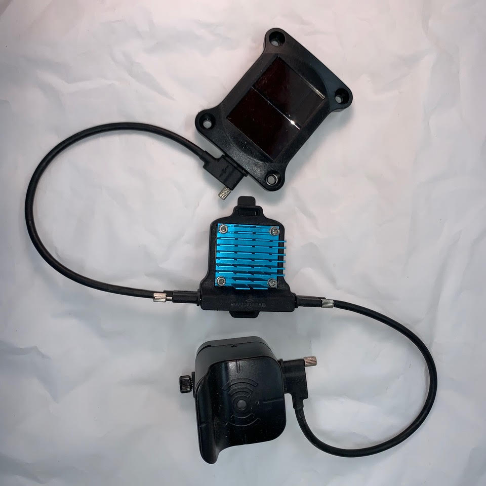
REPORT NO: 13156692-E1V5 DATE: 6/23/2020 FCC ID: 2AO7C-83000001 ISED ID: 23743-83000001 Page 133 of 137 UL VERIFICATION SERVICES INC. 47173 BENICIA STREET, FREMONT, CA 94538, USA TEL: (510) 771-1000 FAX: (510) 661-0888 This report shall not be reproduced except in full, without the written approval of UL Verification Services Inc. 11. SETUP PHOTOS ANTENNA PORT AND AC LINE CONDUCTED SETUP RF ANTENNA PORT CONDUCTED AC LINE CONDUCTED (FRONT) AC LINE CONDUCTED (BACK) REPORT NO: 13156692-E1V5 DATE: 6/23/2020 FCC ID: 2AO7C-83000001 ISED ID: 23743-83000001 Page 134 of 137 UL VERIFICATION SERVICES INC. 47173 BENICIA STREET, FREMONT, CA 94538, USA TEL: (510) 771-1000 FAX: (510) 661-0888 This report shall not be reproduced except in full, without the written approval of UL Verification Services Inc. RADIATED RF MEASUREMENT SETUP BELOW 1GHz CONFIGURATION 1 (FRONT) BELOW 1GHz CONFIGURATION 1 (BACK) BELOW 1GHz CONFIGURATION 2 (FRONT) BELOW 1GHz CONFIGURATION 2 (BACK) REPORT NO: 13156692-E1V5 DATE: 6/23/2020 FCC ID: 2AO7C-83000001 ISED ID: 23743-83000001 Page 135 of 137 UL VERIFICATION SERVICES INC. 47173 BENICIA STREET, FREMONT, CA 94538, USA TEL: (510) 771-1000 FAX: (510) 661-0888 This report shall not be reproduced except in full, without the written approval of UL Verification Services Inc. ABOVE 1GHz CONFIGURATION 1 (FRONT) ABOVE 1GHz CONFIGURATION 1 (BACK) ABOVE 1GHz CONFIGURATION 2 (FRONT) ABOVE 1GHz CONFIGURATION 2 (BACK) BELOW 30MHz (FRONT) ABOVE 30MHz (BACK) REPORT NO: 13156692-E1V5 DATE: 6/23/2020 FCC ID: 2AO7C-83000001 ISED ID: 23743-83000001 Page 136 of 137 UL VERIFICATION SERVICES INC. 47173 BENICIA STREET, FREMONT, CA 94538, USA TEL: (510) 771-1000 FAX: (510) 661-0888 This report shall not be reproduced except in full, without the written approval of UL Verification Services Inc. ORIENTATIONS CONFIGURATION 1 X-ORIENTATION Y-ORIENTATION Z-ORIENTATION REPORT NO: 13156692-E1V5 DATE: 6/23/2020 FCC ID: 2AO7C-83000001 ISED ID: 23743-83000001 Page 137 of 137 UL VERIFICATION SERVICES INC. 47173 BENICIA STREET, FREMONT, CA 94538, USA TEL: (510) 771-1000 FAX: (510) 661-0888 This report shall not be reproduced except in full, without the written approval of UL Verification Services Inc. CONFIGURATION 2 X/Y-ORIENTATION Z-ORIENTATION END OF REPORT
| # | Rule Parts | Frequency Range | Power Output |
|---|---|---|---|
| 1 | 15C | 902 MHz - 928 MHz | 931.00 mW |

Energy Harvesting Sensor Node
Equipment Class
DSS - Part 15 Spread Spectrum Transmitter