2AO93-NM0824-ImPCIe LoRa Concentrator Board
System Level Solutions (India) Pvt. Ltd.
Click to zoom
Application Details
- Equipment Class
- DTS - Digital Transmission System
- Date of Grant
- Jan 03, 2023
- Application Purpose
- Original Equipment
- Date of Application
- Jan 03, 2023
- Equipment Note
- mPCIe LoRa Concentrator Board
- Frequency Range
- 903.00000000 - 927.50000000
- Country
- India
Documents & Files
Document Text
Text extracted from the exhibit documents filed with the FCC. Open a document above to read the original.
Users Manual
User Manual NM0824-I mCPIe based LoRa Concentrator card Author: Nikunj Mehta Date: 12/04/2022 Version / Status: 1.0 Document Library Approver: Lalit Shah Document Classification: Internal Distribution and approvals are maintained in: It is the responsibility of the user of this document to verify that it is the most current edition. Preface Privacy information This document may contain information of a sensitive nature. This information should not be given to any persons outside of the System Level Solutions (I) Pvt. Ltd. without prior consent. Revision history NameDescription of ChangeDateVersion Nikunj MehtaInitial Revision12/04/2022 1.0 Approval NamePositionSignatureDate Lalit ShahManager Email approval received (must be stored in document library with Approved version) Copyright © 2021 System Level Solutions (I) Pvt Ltd. All rights reserved Version: 1.0 Document Classification: Internal Page 2 of31 Table of Contents 1. Introduction..........................................................................................................................................5 1.1. Key Features..............................................................................................................................6 1.2. Applications...............................................................................................................................7 2. LoRa Modulation Technique...............................................................................................................7 3. Module Overview.................................................................................................................................8 3.1. SX1302......................................................................................................................................9 3.2 RF Front End Interface.............................................................................................................10 3.3 Detection Engine – Modems.....................................................................................................11 4. Application Information....................................................................................................................11 4.1. Geographical Designs..............................................................................................................11 4.2. Reference Block Diagram........................................................................................................12 4.3. RF Interface.............................................................................................................................12 4.4. External Module Connector.....................................................................................................12 4.4.1. SPI........................................................................................................................................13 4.4.2. UART....................................................................................................................................13 4.4.3. Digital IOs............................................................................................................................13 4.4.4. LEDs.....................................................................................................................................13 4.4.5. USB-Interface.......................................................................................................................13 4.4.6. Others....................................................................................................................................13 5. LoRa Systems, Network Approach...................................................................................................14 5.1. Overview.................................................................................................................................14 6. Firmware.............................................................................................................................................15 6.1. Cloning of Repository.............................................................................................................15 6.2. Compilation for Raspberry-PI Platform..................................................................................15 6.3. Compilation For Other Platforms............................................................................................16 6.4. Interface Availability...............................................................................................................16 6.5. STM Platform..........................................................................................................................17 7. Electrical Characteristics & Timing specifications.........................................................................17 7.1. Absolute Maximum Ratings....................................................................................................17 Copyright © 2021 System Level Solutions (I) Pvt Ltd. All rights reserved Version: 1.0 Document Classification: Internal Page 3 of31 7.2. Global Electrical Characteristics.............................................................................................18 7.3. SPI Interface Characteristics...................................................................................................18 7.4. RF Characteristics....................................................................................................................20 7.4.1. Transmitter RF Characteristics.............................................................................................20 7.4.2. Receiver RF Characteristics.................................................................................................21 8. Module Package.................................................................................................................................21 8.1…
Text truncated - open the document above for the full version.
Cover Letter(s)
Agent Authorization Company: System Level Solutions (India) Pvt. Ltd. Address: Plot no. 32, Zone-D4, Phase 1 GIDC Estate, V.U. Nagar, Anand – 388121, Gujarat, India Product Name: mPCIe LoRa Concentrator Board Model Number(s): NM0824-I Product Description: The wireless technology and product function how to help people’s life. We authorize MiCOM Labs Inc., 575 Boulder Court, Pleasanton, California 94566, USA, to act on our behalf on all matters concerning the certification of above named equipment. We declare that MiCOM Labs Inc. is allowed to forward all information related to the approval and certification of equipment to the regulatory agencies as required and to discuss any issues concerning the approval application. Any and all acts carried out by MiCOM Labs on our behalf shall have the same effect as acts of our own.
Cover Letter(s)
Federal Communications Commission Equipment Authorization Division 7435 Oakland Mills Road Columbia, MD 21046 USA Date: Subject; Modular Transmitter Application Company name: FCC ID: 2AO93 NM0824-I Dear Sir/Madam, This letter includes the FCC application requirements for Modular Transmitter Approval Request for;- FCC KDB 996369 D01 ‘Module Certification Guide v02; and FCC KDB 996369 D03 OEM Manual v01 In accordance with 47CFR 15.212 Modular Transmitters and KDB 996369 D01 ‘Module Equip Auth Guide v02’. FCC ID 2AO93 - NM0824-l has been examined against the following requirements. Requirement per 15.212 and KDB 996369 D01 Explanation from Grantee (do not write yes/no, but explain why product complies/how it is achieved) The radio elements must have the radio frequency circuitry shielded. Physical components and tuning capacitor(s) may be located external to the shield, but must be on the module assembly. Y - The module has its own RF s hielding. Refer to the external photos. The module must have buffered modulation/data inputs to ensure that the device will comply with Part 15 requirements with any type of input signal. Y - The EUT has buffered modulation/data inputs. It’s integrated on the chipset. The module must contain power supply regulation on the module. Y - Integrated on the chipseT The module must contain a permanently attached antenna, or contain a unique antenna connector, and be marketed and operated only with specific antenna(s), per §§ 15.203, 15.204(b), 15.204(c), 15.212(a), 2.929(b). Y - Licensed modular. The maximum antenna gain is show in RF exposure exhibit. The module must demonstrate compliance in a stand-alone configuration. Y - Tested in a stand - alone configuration The module must be labeled with its permanently affixed FCC ID label, or use an electronic display (see KDB Publication 784748). Y - Refer to external photos . Also the OED manufacturer will be informed to display a label referring to the module. The module must comply with all specific rules applicable to the transmitter, including all the conditions provided in the integration instructions by the grantee. Y - The user manual instruction that the OEM manufacturer how to use/install the module. Refer to the user manuaL The module must comply with RF exposure requirements Y - It is designed for mobile or fixed operation. Name: Himanshu Ankleshwaria Date: 23/12/2022 Title: Senior Manager Signature of applicant:
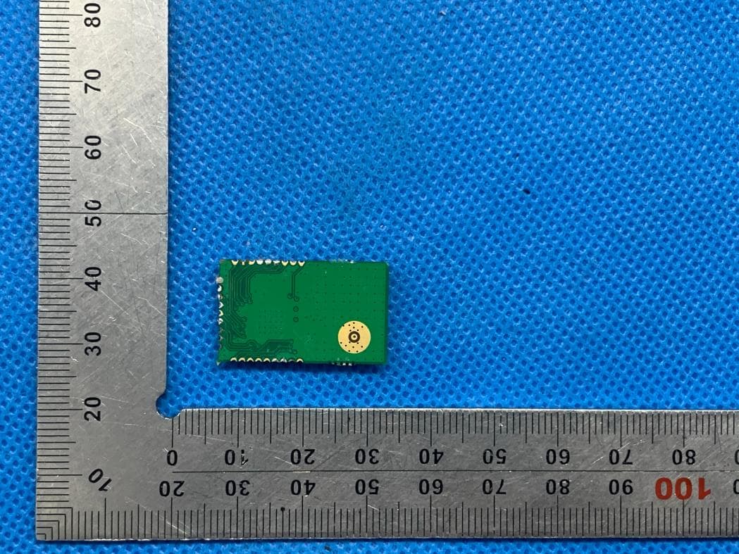
External Photos
EXTERNAL PHOTOS EXTERNAL PHOTOS EXTERNAL PHOTOS
Internal Photos
INTERNAL PHOTOS (WITHOUT SHIELDING CASE)
RF Exposure Info
RF EXPOSURE EVALUATION 1.PRODUCTINFORMATION Product Description mPCIe LoRa Concentrator Board Model Name NM0824-I FCC ID 2AO93–NM0824-I 2.EVALUATION METHODANDLIMIT Human exposure to RF emissions from mobile devices(47CFR§2.1091) may be evaluated based on the MPE limits adopted by the FCC for electric and magnetic field strength and/or power density, as appropriate, since exposures are assumed to occur at distances of 20 cm or more from persons. The device under test (mPCIeLoRa Concentrator Board) is neither a mobile device nor a RF exposure product and it is not closed to 20cm distance from persons LIMITS FOR GENERAL POPULATIONIUNCONTROLLED EXPOSURE Frequency Range (MHz) E-field Strength (E) (V/m) Magnetic Field Strength (H) (A/m) Power Density(S) (mW/cm 2 ) Averaging Time IEl 2 IHl 2 or , S(Minutes) 0.3--1.34 614 1.63 (100)* 30 1.34--30 824/f 2.19/f (180/f 2 )* 30 30--300 27.5 0.073 0.2 30 300--1500 -- -- f/1500 30 1500--100,000 -- -- 1.0 30 *Note: 1.f= Frequency in MHz*Plane-wave Equivalent Power Density 2.The averaging time for General Population/Uncontrolled exposure to fixed transmitters is not applicable for mobile and portable transmitters. (operated in BT/ WIFI) See47CFR§§2.1091 and 2.1093 on source-based time-averaging requirement for mobile and portable transmitters. S=PG/4rrR 2 Where: S=power density P=power input toantenna G=power gain of the antenna in the direction of interest relative to anisotropic radiator R=distance to the center of radiation of the antenna 3. CALCULATION A minimum test separation distance 20cm is required between the antenna and radiating structures of the device and nearby persons to apply mobile device exposure limits. The distance must be at least 20cm and fully supported by the operating and installation configurations of the transmitter and its antenna(s), according to the source-based time-averaged maximum power requirements of §2.1091(d)(2). In cases where cable losses or other attenuations are applied to determine compliance, the most conservative operating configurations and exposure conditions must be evaluated. The device under test (QCS610-410EVK) is neither a mobile device nor a RF exposure product and it is not closed to 20cm distance from persons Antenna Gain (903.0MHz to 927.5MHz (DTS)) = 2.7dBi (Numeric = 1.862), rr = 3.14 Antenna Gain (902.3MHz to 914.9MHz (DSS)) = 2.7dBi (Numeric = 1.862), rr = 3.14 Frequency (MHz) Output Power (dBm) Output Power (mW) Power Density (mW/cm 2) Power Density Limit (mW/cm 2) 927.5 23.72 235.504 0.087282732 0.618 902.3 27.11 514.043 0.190515140 0.618 Note: Only the worst case recorded.
Test Report
Report No.: AAEMT/EMC/220817-01-04 Page | 1 Plot No.174, UdyogVihar Phase 4, Sector -18, Gurgaon -122016, Haryana, India Contact: 0124-4235350, 4145343; e-mail: info @aaemtlabs.com; Website: www.aaemtlabs.com AA Electro Magnetic Test Laboratory Private Limited Certificate#5593.01 FCC ID: 2AO93–NM0824-I FCC Test Report (Part 15 Subpart C) Client Information: Applicant: System Level Solutions (India) Pvt. Ltd. Applicant add.: Plot no. 32, Zone-D4, Phase 1 GIDC Estate, V.U. Nagar, Anand – 388121, Gujarat, India Manufacturer: System Level Solutions (India) Pvt. Ltd. Manufacturer add.: Plot no. 32, Zone-D4, Phase 1 GIDC Estate, V.U. Nagar, Anand – 388121, Gujarat, India Product Information: Product Name: mPCIe LoRa Concentrator Board Model No.: NM0824-I Derivative model No.: N/A Brand Name: SLS Applied Standard: FCC Part 15 Subpart C 15.247 Laboratory Details: AA Electro Magnetic Test Laboratory Private Limited PlotNo174, Udyog Vihar-Phase4, Sector18, Gurgaon, Haryana, India Date of Receipt: Aug. 17, 2022 Date of Test: Aug. 17, 2022 ~ Nov. 24, 2022 Date of Issue: Dec. 08, 2022 Test Result: In Compliance/Pass This device has been tested and found to comply with the stated standard(s), which is (are) required by the council directive of 2014/53/EU and indicated in the test report and are applicable only to the tested sample identified in the report. Note: This report shall not be reproduced except in full, without the written approval of AA Electro Magnetic Test Laboratory Private Limited, this document may be altered or revised by AA Electro Magnetic Test Laboratory Private Limited, personal only, and shall be noted in the revision of the document. This test report must not be used by the client to claim product endorsement. Prepared By (+ signature) Ankur Kumar: Reviewed & Approved by: (+ signature) Dr. Lenin Raja (Authorized Representative) (/ lenin83/) Report No.: AAEMT/EMC/220817-01-04 Page | 2 Plot No.174, UdyogVihar Phase 4, Sector -18, Gurgaon -122016, Haryana, India Contact: 0124-4235350, 4145343; e-mail: info @aaemtlabs.com; Website: www.aaemtlabs.com AA Electro Magnetic Test Laboratory Private Limited Certificate#5593.01 1 Contents Page COVER PAGE 1 CONTENTS ..................................................................................................................................................................... 2 2 TEST SUMMARY ........................................................................................................................................................... 4 2.1 COMPLIANCE WITH FCC PART 15 SUBPART C .............................................................................................................. 4 2.2 TEST LOCATION .......................................................................................................................................................... 5 2.3 MEASUREMENT UNCERTAINTY .................................................................................................................................... 5 3 TEST FACILITY ............................................................................................................................................................. 6 3.1 DEVIATION FROM STANDARD ...................................................................................................................................... 6 3.2 ABNORMALITIES FROM STANDARD CONDITIONS ........................................................................................................... 6 4 GENERAL INFORMATION .......................................................................................................................................... 7 4.1 GENERAL DESCRIPTION OF EUT .................................................................................................................................. 7 4.2 DESCRIPTION OF TEST CONDITIONS .............................................................................................................................. 9 4.3 TEST PERIPHERAL LIST ............................................................................................................................................. 10 4.4 EUT PERIPHERAL LIST .............................................................................................................................................. 10 5 EQUIPMENTS LIST FOR ALL TEST ITEMS ........................................................................................................... 11 6 TEST RESULT .............................................................................................................................................................. 13 6.1 ANTENNA REQUIREMENT .......................................................................................................................................... 13 6.1.1 Standard requirement ....................................................................................................................................... 13 6.1.2 EUT Antenna ................................................................................................................................................... 13 6.2 CONDUCTION EMISSIONS MEASUREMENT .................................................................................................................. 14 6.2.1 Applied procedures / Limit ............................................................................................................................... 14 6.2.2 Test procedure ................................................................................................................................................. 14 6.2.3 Test setup ........................................................................................................................................................ 14 6.2.4 Test results.......................................................................................................................................…
Text truncated - open the document above for the full version.
Test Report
Datasheet ANT-915-IPW1-RPS 915 MHz LPWA Weatherproof Antenna Applications • Low-power, wide-area (LPWA) applications ―LoRaWAN ® , ITU-T Y.4480 ―WiFi HaLow™ (802.11ah) • Remote control, monitoring and sensing • Internet of Things (IoT) devices • ISM applications Features • Performance at 902 MHz to 930 MHz ―VSWR: ≤ 1.8 ―Peak Gain: 2.7 dBi ―Efficiency: 99% • Hinged design with detents for straight, 45 degree and 90 degree positioning • IP67 rated • RP-SMA plug (female socket) connector The ANT-915-IPW1-RPS antenna is a hinged-whip IP67-rated dipole antenna designed for use in 915 MHz frequency bands for low-power, wide-area (LPWA) applications such as LoRaWAN ® and WiFi HaLow™ as well as ISM and remote control applications. The ANT-915-IPW1-RPS provides a ground plane independent dipole antenna solution. The hinged design allows for the antenna to be positioned for optimum performance and reduces the potential for damage from impact compared to a fixed whip design. The antenna attaches with an RP-SMA plug (female socket) connector. Ordering Information Part NumberDescription ANT-915-IPW1-RPS Hinged whip LPWA antenna with RP-SMA plug (female socket) connector Available from Linx Technologies and select distributors and representatives. 2 DatasheetANT-915-IPW1-RPS IP (Ingress Protection) Rating An ingress protection rating (IP rating) refers to the capability of a device to withstand the ingress of dust and/or water under specified conditions. IP rating is typically reserved for marketable product (device) rather than constituent components because design and assembly may affect performance of the device under testing. IP-rated antennas are designed to support the specified level of ingress protection and may be tested in a standalone configuration, however IP testing should be performed on the complete end product to ensure desired performance. Table 1. Electrical Specifications ANT-915-IPW1-RPS915 MHz Frequency Range 902 MHz to 930 MHz VSWR (max.) 1.8 Peak Gain (dBi) 2.7 Average Gain (dBi) - 0 .1 Efficiency (%) 99 Impedance 50 Ω Wavelength 1/2-wave Electrical Type Dipole Polarization Linear Radiation Omnidirectional Max Power 2 W Electrical specifications and plots measured with the antenna at the edge of a 102 mm x 102 mm ground plane, bent 90 degrees. Table 2. Mechanical Specifications ParameterValue Connection RP-SMA plug (female socket) Operating Temperature Range -30 °C to +70 °C Ingress Protection Rating (IP) IP67 rated Antenna Color Black Weight 24.9 g (0.88 oz) Dimensions 203.0 mm x 13.2 mm x 13.2 mm (7.99 in x 0.52 in x 0.52 in) Product Dimensions Figure 1 provides dimensions of the ANT-915-IPW1-RPS. The antenna whip can be tilted 90 degrees, with a detent at 45 degrees enabling the antenna to be oriented in any direction. The rotating base allows for continuous positioning through 360 degrees even while installed. 37.6 mm (1.48 in) Ø13.2 mm (0.52 in) 203.0 mm (7.99 in) Full 360° rotation 178.7 mm (7.04 in) 0°, 45°, 90° 13.2mm 0.52in 203.0mm 7.99in 37.6mm 1.48in 13.2mm 0.52in 178.7mm 7.04in Figure 1. ANT-915-IPW1-RPS Antenna Dimensions 3 DatasheetANT-915-IPW1-RPS Antenna Orientation The ANT-915-IPW1-RPS antenna is characterized in two antenna orientations as shown in Figure 2. The antenna straight orientation characterizes use of an antenna attached to an enclosure-mounted connector which is connected by cable to a printed circuit board. Although the antenna is a dipole not requiring a ground plane for function, characterization with an adjacent ground plane, (102 mm x 102 mm) provides insight into antenna performance when attached directly to a printed circuit board mounted connector. The two orientations represent the most common end-product use cases. On edge of ground plane, bent 90 degreesStraight, without ground plane Figure 2. ANT-915-IPW1-RPS Antenna on Evaluation PCB LPWA: LoRaWAN ® ITU-T Y.4480, and Sigfox ® LoRaWAN and Sigfox LPWA technologies operate within several of the frequencies supported by the 915-IPW1-RPS antenna. Notably, LoRaWAN operates at the frequency bands shown in Ta b l e 3. Sigfox operates at different frequencies determined by country (Ta b l e 4). Table 3. LoRaWAN ® Channel plan Frequency BandLoRaWAN Channel Plan 779 MHz to 787 MHzCN779-787 865 MHz to 867 MHzIN765-867 868 MHz to 873 MHzEU863-870 902 MHz to 928 MHzUS902-928, AS923 915 MHz to 928 MHzAU915-928 917 MHz to 923.5 MHzKR920-923 Table 4. Sigfox ® Frequencies by Country/Region Center FrequencySelect Countries/Regions 868 MHzEurope 902 MHzUSA, Mexico, Brazil 920 MHzAustralia 923 MHzJapan Packaging Information The ANT-915-IPW1-RPS antenna is packaged in a plastic bag. Distribution channels may offer alternative packaging options. 4 DatasheetANT-915-IPW1-RPS Edge of Ground Plane The charts on the following pages represent data taken with the antenna oriented at the edge of the ground plane, bent 90 degrees as shown in Figure 3. Figure 3. ANT-915-IPW1-RPS at Edge of Ground Plane, Bent 90 Degrees (Edge Bent) VSWR Figure 4 provides the voltage standing wave ratio (VSWR) across the antenna bandwidth. VSWR describes the power reflected from the antenna back to the radio. A lower VSWR value indicates better antenna performance at a given frequency. Reflected power is also shown on the right-side vertical axis as a gauge of the percentage of transmitter power reflected back from the antenna. 915902930 0 10 20 30 40 1 2 3 4 5 900905910915920925930935 Reflected Power (%) VSWR Frequency (MHz) Figure 4. ANT-915-IPW1-RPS Antenna VSWR, Edge Bent 5 DatasheetANT-915-IPW1-RPS Return Loss Return loss (Figure 5), represents the loss in power at the antenna due to reflected signals. Like VSWR, a lower return loss value indicates better antenna performance at a given frequency. 915902930 -20 -18 -16 -14 -12 -10 -8 -6 -4 -2 0 900905910915920925930935 Return Loss (dB) Frequency (MHz) Figure 5. ANT-915-IPW1-RPS Antenna Return Loss, Edge Bent Peak Gain The peak gain across the antenna bandwidth is shown in Figure 6. Pea…
Text truncated - open the document above for the full version.
Test Setup Photos
Test Setup photographs
Contact Information
Applicant
Himanshu Ankleshwaria
Technical Contact
Test Firm
AA Electro Magnetic Test LaboratoryJackie Deng
[email protected]911244235350
Technical Specifications
| # | Rule Parts | Frequency Range | Power Output |
|---|---|---|---|
| 1 | 15C | 903 MHz - 927.5 MHz | 235.50 mW |
Other Applications from System Level Solutions (India) Pvt. Ltd.
2AO93PI0NN100C1100
Sep 23, 2020NLN100C-1
Equipment Class
DTS - Digital Transmission System