2AO93PI0NN100C1100NLN100C-1
System Level Solutions (India) Pvt. Ltd.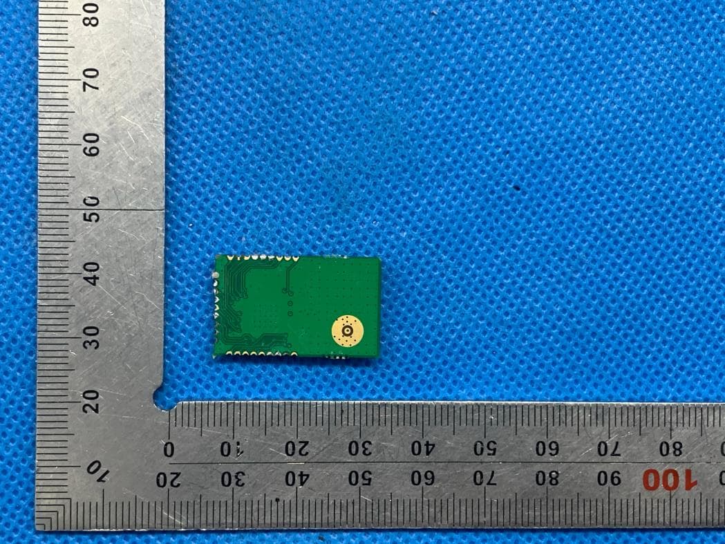
Click to zoom
Application Details
- Equipment Class
- DTS - Digital Transmission System
- Date of Grant
- Sep 23, 2020
- Application Purpose
- Original Equipment
- Date of Application
- Sep 22, 2020
- Equipment Note
- NLN100C-1
- Frequency Range
- 2405.00000000 - 2480.00000000
- Country
- India
Documents & Files
Document Text
Text extracted from the exhibit documents filed with the FCC. Open a document above to read the original.
Users Manual
System Level Solutions, Inc. (USA) 511 N. Washington Avenue Marshall, Texas 75670. (408) 852 - 0067 http://www.slscorp.com Node Version: 1A Document Version:1.2 Document Date: November 2019 NebuLink Node NLN 100C Datasheet ii NebuLink Node NLN 100C Datasheet System Level Solutions November 2019 Copyright ©2019, System Level Solutions, Inc. (SLS) All rights reserved. SLS, an Embedded systems company, the stylized SLS logo, specific device designations, and all other words and logos that are identified as trademarks and/or service marks are, unless noted otherwise, the trademarks and service marks of SLS in India and other countries. All other products or service names are the property of their respective holders. SLS products are protected under numerous U.S. and foreign patents and pending applications, mask working rights, and copyrights. SLS reserves the right to make changes to any products and services at any time without notice. SLS assumes no responsibility or liability arising out of the application or use of any information, products, or service described herein except as expressly agreed to in writing by SLS. SLS customers are advised to obtain the latest version of specifications before relying on any published information and before orders for products or services. ds_nln100c_1.2 iiiSystem Level Solutions NebuLink Node NLN 100C Datasheet November 2019 About this Manual Revision History Table below shows the revision history of NebuLink Node NLN 100C’s datasheet. VersionDateDescription 1.2November 2019Added note in Table 1-1 1.1April 2019Added Figure 1.1 and Chapter 4 Updated Table 1.1 in Chapter 1 1.0July 2018First publication How to Contact SLS For the most up-to-date information about SLS products, go to the SLS worldwide website at http://www.slscorp.com. For additional information about SLS products, consult the source shown below Information TypeE-mail Product literature services, SLS literature services, Non-technical customer services, Technical support. [email protected] iv NebuLink Node NLN 100C Datasheet System Level Solutions November 2019 Typographic Conventions This datasheet uses the typographic conventions as shown below: Visual CueMeaning Bold Type with Initial Capital letters All headings and Sub headings Titles in a document are displayed in bold type with initial capital letters; Example: General Description, Features. Bold Type with Italic LettersAll Definitions, Figure and Table Head ings are displayed in Italics. Examples: Figure 1-1. NebuLink Node NLN 100C, Table 1-1. NebuLink Node NLN 100C Specifications. 1., 2. Numbered steps are used in a list of items, when the sequence of items is important. such as steps listed in procedure. • Bullets are used in a list of items when the sequence of items is not important. The hand points to special information that requires special attention The caution indicates required information that needs special consideration and understanding and should be read prior to starting or continuing with the procedure or process. The warning indicates information that should be read prior to starting or continuing the procedure or processes. The feet direct you to more information on a particular topic. vSystem Level Solutions NebuLink Node NLN 100C Datasheet November 2019 Contents About this Manual..............................................................................................................iii Revision History ......................................................................................................................................iii How to Contact SLS ................................................................................................................................iii Typographic Conventions........................................................................................................................iv 1. Overview .................................................................................................................................... 1 General Description..................................................................................................................................1 Benefits .....................................................................................................................................................2 Specifications............................................................................................................................................5 Node Accessories......................................................................................................................................6 2. Pin-Out Information .................................................................................................................. 7 3. Package Information ............................................................................................................... 10 4. Test Report ..............................................................................................................................12 1System Level Solutions NebuLink Node NLN 100C Datasheet November 2019 1. Overview General Description The NebuLink Node NLN 100C provides a means for any electronic device to implement low cost wireless connectivity. This Node inter operates with either Zigbee or 6LoWPAN devices depending on the programmed stack. NLN 100C is ideal for applications in the energy and controls markets where manufacturing efficiencies are critical. The NLN 100C, built around the NX P JN5169 SoC (system on a chip) radio IC, integrates an 802.15.4 radio along with a powerful programmable 32-bit RISC CPU. The architecture isolates the wireless software without sacrificing RF performance or security for applications. Thus, allows to create customized applications quickly and efficiently. Figure 1-1. shows an overview of the product. Figure 1-1. NebuLink Node NLN 100C Overview NLN 100C-1 NLN 100C-2 NLN 100C-3 Benefits 2…
Text truncated - open the document above for the full version.
Cover Letter(s)
System Level Solutions (India) Pvt. Ltd. RE FCC ID: 2AO93PI0NN100C1100 To the certification reviewer: We are hereby applying for [full] modular approval of the above-referenced FCC ID, based on compliance with [all] of the criteria as detailed below. Sincerely, System Level Solutions (India) Pvt. Ltd. Contact person: Himanshu Ankleshwaria Part 15 Unlicensed Single Modular Transmitter Approval Justification per 15.212 Requirement per 15.212 reference (i) The radio elements of the modular transmitter must have their own RF shielding. Shielding is provided by a metal cover over the circuitry. (ii) The modular transmitter must have buffered modulation/data inputs (if such inputs are provided. All modulation and data inputs are buffered by circuitry on the transmitter chip. (iii) The modular transmitter must have its own power supply regulation. Power supply regulation is provided by circuitry on the transmitter chip. (iv) The modular transmitter must comply with the antenna and transmission system requirements of §§ 15.203, 15.204(b) and 15.204(c). The antenna is fixed. (v) The modular transmitter must be tested in a stand-alone configuration, i.e., the module must not be inside another device during testing for compliance with Part 15 parameters. Testing was performed in a stand-alone configuration as shown in the test setup photos. (vi) The modular transmitter must be equipped with either a permanently affixed label or must be capable of electronically displaying its FCC identification number. If the FCC ID is not visible when the module is installed inside another device, then the outside of the device into which the module is installed must also display a label referring to the enclosed module. The modular was labeled with its own FCC ID. The outside of device in to which the module is installed will labeled Contains TX FCC ID: 2AO93PI0NN100C1100, Please refer to User Manual. System Level Solutions (India) Pvt. Ltd. (vii) The modular transmitter must comply with any specific rules or operating requirements that ordinarily apply to a complete transmitter and the manufacturer must provide adequate instructions along with the module to explain any such requirements. A copy of these instructions must be included in the application for equipment authorization. The modular is comply with all applicable FCC rules. Any modifications, not expressly approved by the manufacturer could void the authority to operate in these regions. (viii) The modular transmitter must comply with any applicable RF exposure requirements in its final configuration. This module operates under Part 15 .247 which is exempt from RF exposure evaluation owing to the very low operating power.
Cover Letter(s)
System Level Solutions (India) Pvt. Ltd. Agent Authorization Company: System Level Solutions (India) Pvt. Ltd. Address: Plot#32, Zone-D/4, Phase-1, GIDC Estate, V.U. Nagar -388 121, Gujarat, India Product Name: NLN100C-1 Model Number(s): PI0NN100C1100 Product Description: NLN100C-1 We authorize MiCOM Labs Inc., 575 Boulder Court, Pleasanton, California 94566, USA, to act on our behalf on all matters concerning the certification of above named equipment. We declare that MiCOM Labs Inc. is allowed to forward all information related to the approval and certification of equipment to the regulatory agencies as required and to discuss any issues concerning the approval application. Any and all acts carried out by MiCOM Labs on our behalf shall have the same effect as acts of our own. Signature: Date: 2020-08-25 Name: Himanshu Ankleshwaria Company: System Level Solutions (India) Pvt. Ltd.
Cover Letter(s)
System Level Solutions (India) Pvt. Ltd. Office of Engineering Technology Federal Communications Commission 7435 Oakland Mills Road Columbia, MD 21046 USA Date: 2020-06-23 Subject; Request for Confidentiality FCC ID: 2AO93PI0NN100C1100 To Whom It May Concern, Pursuant to the provisions of the Commission’s rules Title 47 Sections §0.457 and §0.459, we are requesting the Commission to withhold the following attachment(s) as confidential documents from public disclosure indefinitely. These documents contain detailed system and equipment descriptions and are considered as proprietary information in operation of the equipment. The public disclosure of these documents might be harmful to our company and would give competitors an unfair advantage in the market. Schematic Diagram Block Diagram Parts List Operational Description Tune-up Procedure In additional to above mentioned documents, in order to comply with the marketing regulations in Title 47 CFR §2.803 and the importation rules in Title 47 CFR §2.1204, while ensuring that business sensitive information remains confidential until the actual marketing of newly authorized devices, we request Short Term Confidentiality of the following attachment(s); External Photos Test Setup Photos Internal Photos User Manual For 45 days, pursuant to Public Notice DA 04-1705. OR For 180 days pursuant to KDB 726920 D01. It is our understanding that all measurement test reports, FCC ID label format and correspondence during the certification review process cannot be granted as confidential documents and this information will be available for public review once the grant of equipment authorization is issued. Sincerely, System Level Solutions (India) Pvt. Ltd. System Level Solutions (India) Pvt. Ltd. Contact person: Himanshu Ankleshwaria
External Photos
External Photos All VIEW OF EUT FRONT VIEW OF EUT Antenna BACK VIEW OF EUT ANTENNA CONNECTOR
ID Label/Location Info
FCC ID Label Location FCC ID: 2AO93PI0NN100C1100
Internal Photos
Internal Photos INTERNAL VIEW OF EUT(FIGURE 1) INTERNAL VIEW OF EUT(FIGURE 2) INTERNAL VIEW OF EUT(FIGURE 3)
RF Exposure Info
RF EXPOSURE EVALUATION 1. PRODUCT INFORMATION Product Description NLN100C-1 Model Name PI0NN100C1100 FCC ID 2AO93PI0NN100C1100 2. EVALUATION METHOD According to 447498 D01 General RF Exposure Guidance v05 The 1-g and 10-g SAR test exclusion thresholds for 100 MHz to 6 GHz at test separation distances ≤ 50 mm are determined by: [(max. power of channel, including tune-up tolerance, mW)/(min. test separation distance, mm)] ·[√f(GHz)] ≤ 3.0 for 1-g SAR and ≤ 7.5 for 10-g extremity SAR. Where f(GHz) is the RF channel transmit frequency in GHz Power and distance are rounded to the nearest mW and mm before calculation 3. CALCULATION P t =9.095dBm=8.12mW The value of the Maximum output power P t is referred to the test report of the CFR47 §15.247. The result for RF exposure evaluation SAR=(8.12mW /5mm) .[√2.405(GHz)]=2.52<3.0 for 1-g SAR and ≤ 7.5 for 10-g extremity SAR. 4. CONCLUSION The SAR evaluation is not required.
Test Report
Page 1 of 45 FCC Test Report Report No.: AGC01125180410FE02 FCC ID : 2AO93PI0NN100C1100 APPLICATION PURPOSE : Original Equipment PRODUCT DESIGNATION : NLN100C-1 BRAND NAME : Nebulae MODEL NAME : PI0NN100C1100 APPLICANT : System Level Solutions (India) Pvt. Ltd. DAT E O F ISSUE : Jun. 23, 2020 STANDARD(S) : FCC Part 15.247 REPORT VERSION : V1.0 Attestation of Global Compliance (Shenzhen) Co., Ltd CAUTION: This report shall not be reproduced except in full without the written permission of the test laboratory and shall not be quoted out of context. Report No.: AGC01125180410FE02 Page 2 of 45 REPORT REVISE RECORD Report Version Revise Time Issued Date Valid Version Notes V1.0 / Jun. 23, 2020 Valid Initial Release Report No.: AGC01125180410FE02 Page 3 of 45 TABLE OF CONTENTS 1. VERIFICATION OF COMPLIANCE ............................................................................................................... 5 2.GENERAL INFORMATION ............................................................................................................................. 6 2.1PRODUCT DESCRIPTION ...................................................................................................................... 6 2.2. TABLE OF CARRIER FREQUENCYS ................................................................................................... 6 2.3 RELATED SUBMITTAL(S)/GRANT(S) ................................................................................................... 7 2.4TEST METHODOLOGY .......................................................................................................................... 7 2.5 SPECIAL ACCESSORIES ...................................................................................................................... 7 2.6 EQUIPMENT MODIFICATIONS ............................................................................................................. 7 2.7 ANTENNA REQUIREMENT ................................................................................................................... 7 3. MEASUREMENT UNCERTAINTY ................................................................................................................. 8 4. DESCRIPTION OF TEST MODES ................................................................................................................. 9 5. SYSTEM TEST CONFIGURATION ............................................................................................................. 10 5.1 CONFIGURATION OF TESTED SYSTEM ........................................................................................... 10 5.2 EQUIPMENT USED IN TESTED SYSTEM .......................................................................................... 10 5.3. SUMMARY OF TEST RESULTS ......................................................................................................... 10 6. TEST FACILITY ........................................................................................................................................... 11 7. PEAK OUTPUT POWER ............................................................................................................................. 12 7.1. MEASUREMENT PROCEDURE ......................................................................................................... 12 7.2. TEST SET-UP (BLOCK DIAGRAM OF CONFIGURATION) ............................................................... 12 7.3. LIMITS AND MEASUREMENT RESULT ............................................................................................. 13 8. 6 DB BANDWIDTH ...................................................................................................................................... 15 8.1. MEASUREMENT PROCEDURE ......................................................................................................... 15 8.2. TEST SET-UP (BLOCK DIAGRAM OF CONFIGURATION) ............................................................... 15 8.3. LIMITS AND MEASUREMENT RESULTS .......................................................................................... 15 9. CONDUCTED SPURIOUS EMISSION ........................................................................................................ 17 9.1. MEASUREMENT PROCEDURE ......................................................................................................... 17 9.2. TEST SET-UP (BLOCK DIAGRAM OF CONFIGURATION) ............................................................... 17 9.3. MEASUREMENT EQUIPMENT USED ................................................................................................ 17 9.4. LIMITS AND MEASUREMENT RESULT ............................................................................................. 17 10. MAXIMUM CONDUCTED OUTPUT POWER SPECTRAL DENSITY ....................................................... 22 10.1 MEASUREMENT PROCEDURE ........................................................................................................ 22 10.2 TEST SET-UP (BLOCK DIAGRAM OF CONFIGURATION) .............................................................. 22 10.3 MEASUREMENT EQUIPMENT USED ............................................................................................... 22 10.4 LIMITS AND MEASUREMENT RESULT ............................................................................................ 22 Report No.: AGC01125180410FE02 Page 4 of 45 11. RADIATED EMISSION ............................................................................................................................... 24 11.1. MEASUREMENT PROCEDURE ....................................................................................................... 24 11.2. TEST SETUP ..................................................................................................................................... 25 11.3. LIMITS AND MEASUREMENT RESULT .........................................................................…
Text truncated - open the document above for the full version.
Test Setup Photos
Test Setup Photos RADIATED EMISSION TEST SETUP BELOW 1GHZ RADIATED EMISSION TEST SETUP ABOVE 1GHZ CONDUCTED EMISSION TEST SETUP
Contact Information
Applicant
Himanshu Ankleshwaria
Technical Contact
Test Firm
Attestation of Global Compliance (Shenzhen) Co., LDoris Li
[email protected]+86-755-25234088
Technical Specifications
| # | Rule Parts | Frequency Range | Power Output |
|---|---|---|---|
| 1 | 15C | 2.40 GHz - 2.48 GHz | 8.00 mW |
Other Applications from System Level Solutions (India) Pvt. Ltd.

2AO93-NM0824-I
Jan 03, 2023mPCIe LoRa Concentrator Board
Equipment Class
DTS - Digital Transmission System