2AOFP-E0058COPA Mesh E0058 Rev. A
Anticimex Innovation Center A/S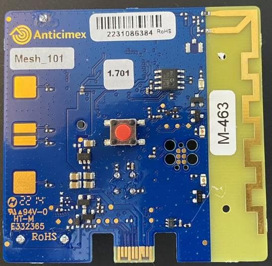
Click to zoom
Application Details
- Equipment Class
- DTS - Digital Transmission System
- Date of Grant
- Jul 30, 2023
- Application Purpose
- Original Equipment
- Date of Application
- Jul 30, 2023
- Equipment Note
- COPA Mesh E0058 Rev. A
- Frequency Range
- 917.00000000 - 926.00000000
- Country
- Denmark
Documents & Files
Document Text
Text extracted from the exhibit documents filed with the FCC. Open a document above to read the original.
Users Manual
1/14 Anticimex Innovation Center A/S Skovgaardsvej 25 3200 Helsinge, Denmark Phone +45 48 79 93 78, [email protected] anticimex.com/innovationcenter Reg no. DK30350766 Registered office: Helsinge Integration guide COPA Mesh FCC ID: 2AOFP- E0058 2/14 Anticimex Innovation Center A/S Skovgaardsvej 25 3200 Helsinge, Denmark Phone +45 48 79 93 78, [email protected] anticimex.com/innovationcenter Reg no. DK30350766 Registered office: Helsinge Table of Contents References.............................................................................................. Fejl! Bogmærke er ikke defineret. COPA Mesh module overview ............................................................................................................................. 3 Compliance statement ....................................................................................................................................... 3 COPA Mesh module block diagram ............................................................................................................. 4 Module features ................................................................................................................................................... 5 Connector mapping............................................................................................................................................ 6 Power Architecture.............................................................................................................................................. 6 Radio description ..................................................................................................................................................... 8 COPA Mesh module hardware implementation ...................................................................................... 8 Receive path .......................................................................................................................................................... 9 Transmit path ........................................................................................................................................................ 9 SUB-GHz Signal characteristics for FCC compliance ........................................................................... 10 SUB-GHz Signal characteristics for EU compliance ............................................................................. 10 Antenna system ..................................................................................................................................................... 11 Mesh board antenna ....................................................................................................................................... 11 Max gain measured ..................................................................................................................................... 11 Integration instructions....................................................................................................................................... 13 Label requirements .......................................................................................................................................... 13 Allowed operating frequencies; .................................................................................................................. 13 Other ..................................................................................................................................................................... 13 PCB layer stackup ............................................................................................................................................. 13 3/14 Anticimex Innovation Center A/S Skovgaardsvej 25 3200 Helsinge, Denmark Phone +45 48 79 93 78, [email protected] anticimex.com/innovationcenter Reg no. DK30350766 Registered office: Helsinge COPA Mesh module overview The COPA mesh module consists of a sub-GHz wireless MCU (CC1312R7 from TI), a PCB antenna, a Lithium-type battery, memory, PIR sensor, power circuitry, temperature sensor, LEDs and several different GPIOs to interface with the outside world. A COPA Mesh board can be used in a gateway or as a stand-alone board in a sensor device handling sensor data communication within a mesh network. Sensors could include; PIR devices and rodent traps. Compliance statement This device complies with part 15 of the FCC Rules. Operation is subject to the following two conditions: (1) This device may not cause harmful interference, and (2) this device must accept any interference received, including interference that may cause undesired operation. (47 CFR 15.19) Caution: any changes or modifications not expressly approved by Anticimex Innovation Center A/S will void the user’s authority to operate the equipment (47 CFR 15.21) The antenna is fixed to the device and no change in antenna or fixation of the antenna is acceptable and such modification is considered to violate the Compliance Statement. The Copa Mesh module is in compliance with the requirement for RF exposure in US with 20 cm separation distance between the user and/or bystander of the device. As per 47 CFR 15.105 this equipment has been tested and found to comply with the limits for a Class B digital device, pursuant to part 15 of the FCC Rules. These limits are designed to provide reasonable protection against harmful interference in a residential installation. This equipment generates, uses, and can radiate radio frequency energy and, if not installed and used in accordance with the instructions, may cause harmful interference to radio communications. However, there is no guarantee that interference will not occur in a particular installation. If this equipment does cause harmful interference to radio or television reception, which can be determined by turning the equipment off and on, the user is encouraged to try to correct the interference by one or more of the f…
Text truncated - open the document above for the full version.
Attestation Statements
COMPANY LETTERHEAD Covered Equipment Certification Attestation Letter 6/23/2023 Nemko North America, Inc. 303 River Road Ottawa K1V 1H2 Canada ATTN.: Reviewing Engineer FCC ID: 2AOFP- E0058 Anticimex Innovation Center A/S (“the applicant”) certifies that the equipment for which authorization is sought is not “covered” equipment prohibited from receiving an equipment authorization pursuant to section 2.903 of the FCC rules. Note: If the equipment for which the applicant seeks authorization is produced by any of the entities identified on the current Covered List, the applicant should include an explanation on why the equipment is not “covered” equipment. Anticimex Innovation Center A/S (“the applicant”) certifies that, as of the date of the filing of the application, the applicant is not identified on the Covered List as an entity producing “covered” equipment. Signed: Printed name: Emil Hjorth Espensen Title: Certification Manager Company Name: Anticimex Innovation Center A/S Date: 6/23/2023
Cover Letter(s)
COMPANY LETTERHEAD 5/19/2023 Nemko North America, Inc. 303 River Road Ottawa, Ontario, Canada K1V 1H2 AUTHORITY TO ACT AS AGENT - FCC On our behalf, I appoint Dana Cote, Anticimex Inc, to act as our agent in the preparation of this application for equipment certification. I certify that submitted documents properly describe the device or system for which equipment certification is sought. I also certify that each unit manufactured, imported or marketed, as defined in FCC regulations will have affixed to it a label identical to that submitted for approval with this application. In signing this letter, Applicant certifies that neither the applicant nor any party to the application is not subject to a denial of Federal benefits, that include FCC benefits, pursuant to Section 5301 of the Anti-Drug Abuse Act of 1988, 21 U.S.C. § 862 because of a conviction for possession or distribution of a controlled substance. See 47 CFR 1.2002(b) for the definition of a "party" for these purposes. For instances where our authorized agent signs the application for certification on our behalf, I acknowledge that all responsibility for complying with the terms and conditions for certification, as specified by Nemko North America Inc., still resides still resides with us. Sincerely, Printed name: Emil Hjorth Espensen
Cover Letter(s)
COMPANY LETTERHEAD Covered Equipment Certification Attestation Letter 6/23/2023 Nemko North America, Inc. 303 River Road Ottawa K1V 1H2 Canada ATTN.: Reviewing Engineer FCC ID: 2AOFP- E0058 Anticimex Innovation Center A/S (“the applicant”) certifies that the equipment for which authorization is sought is not “covered” equipment prohibited from receiving an equipment authorization pursuant to section 2.903 of the FCC rules. Note: If the equipment for which the applicant seeks authorization is produced by any of the entities identified on the current Covered List, the applicant should include an explanation on why the equipment is not “covered” equipment. Anticimex Innovation Center A/S (“the applicant”) certifies that, as of the date of the filing of the application, the applicant is not identified on the Covered List as an entity producing “covered” equipment. Signed: Printed name: Emil Hjorth Espensen Title: Certification Manager Company Name: Anticimex Innovation Center A/S Date: 6/23/2023
Cover Letter(s)
July 17, 2023 Nemko North America, Inc. 303 River Road Ottawa, Ontario, Canada K1V 1H2 REQUEST FOR CONFIDENTIALITY - FCC FCC ID: 2AOFP-E0058 Pursuant to Sections 0.457(d) and 0.459 of the Commission’s Rules and FCC Guidance document 726920, we hereby request permanent confidential treatment of exhibits identified as such in the table below and request they are permanently withheld from public review based on the documents containing trade secrets and proprietary information not customarily released to the public. The public disclosure of this information might be harmful to the applicant and provide unjustified benefits to its competitors. We also request short-term confidentiality on certain exhibits until the intended date of marketing as outlined below. We request the exhibits be withheld from public view for a period of 0 days. We attest marketing of the product will only commence after the period of short-term confidentiality expires, or if marketing is to commence before the requested number of days listed above, the grantee will inform Nemko to release the Short-Term Confidentiality information withheld on the FCC equipment authorization website. Exhibit Type of Confidentiality Requested Block Diagrams ☒ Permanent ☐ Short Term External Photos ------------------ ☒ Short Term Internal Photos ☐ Permanent* ☒ Short Term Operation Description ☒ Permanent ☐ Short Term Parts List & Placement/BOM ☒ Permanent ☐ Short Term Tune-Up Procedure ☒ Permanent ☐ Short Term Schematic Diagrams ☒ Permanent ☐ Short Term Test Setup Photos ------------------ ☒ Short Term User’s Manual ☐ Permanent* ☒ Short Term The asterisked items (*) require further information to be provided in this justification letter before permanent confidentiality will be extended to these exhibits. Please refer to FCC KDB 726920 D01 found at: https://apps.fcc.gov/oetcf/kdb/forms/FTSSearchResultPage.cfm?switch=P&id=41731 and review section II, 3) regarding specific information that must accompany these requests. Note: any documents held under the Short-Term confidentiality will automatically become public after the requested time if an appropriate extension request has not been received. Any exhibits (i.e., schematic diagrams) that may have already been requested to have “Permanent” confidentiality as shown above need not be repeated under Short-Term confidentiality request. Sincerely, Signed: Printed name: Emil Bonnevie Title: Electronics Engineer Company Name: Anticimex Innovation Center A/S
Cover Letter(s)
Date (17/05/2023) Federal Communications Commission Equipment Authorization Branch 7435 Oakland Mills Road Columbia, MD 21046 Modular Approval Request FCC ID: 2AOFP-E0058 The following attestation addresses the requirements to support modular approval: Modular approval requirement Yes (provide brief statement) No * (a) The radio elements must have the radio frequency circuitry shielded. Physical components and tuning capacitor(s) may be located external to the shield, but must be on the module assembly The modular transmitter has PCB ground planes and a shield can over the radio parts including crystals. (b) The module must have buffered modulation/data inputs to ensure that the device will comply with Part 15 requirements with any type of input signal The modular transmitter has buffered modulation/data inputs ensure compliance with Part 15 under conditions of excessive data rates or overmodulation. All inputs are buffered through logic or microprocessor inputs. (c) The module must contain power supply regulation on the module The modular transmitter has its own power supply regulation in the form of a low drop-out regulator providing 3.3V supply voltage to the board independently if the board is powered by the on-board battery or an external source. (d) The module must contain a permanently attached antenna, or contain a unique antenna connector, and be marketed and operated only with specific antenna(s), per Sections 15.203, 15.204(b), 15.204(c), 15.212(a), 2.929(b) The module contains a permanently attached IFA-type Antenna (e) The module must demonstrate compliance in a stand-alone configuration The module complies to Part 15 in a stand-alone configuration (f) The module must be labelled with its permanently affixed FCC ID label, or use an electronic display (See KDB Publication 784748 about labelling requirements) The modular transmitter is labeled with its own FCC ID number. Because the modular transmitter may be installed inside another device, rendering its own label invisible, the integration guide of the modular transmitter informs that the host device must visibly display the necessary text (Contains FCC ID: 2AOFP-E0058) on the outside of the finished product (g) The module must comply with all specific rules applicable to the transmitter. The grantee must provide comprehensive instructions to explain compliance requirements The module is compliant with all applicable FCC rules. Instructions for maintaining compliance are given in the integration guide Modular approval requirement Yes (provide brief statement) No * (h) The module must comply with RF exposure requirements The module is compliant with all applicable RF exposure requirements. * Please provide a detailed explanation if the answer is “No.” Sincerely, Signed: Printed name: Emil Hjorth Espensen Title: Certification Manager
External Photos
E0058 External photos
ID Label/Location Info
Label to be placed here QR code = Mac address + Reference no. Production site Label specifications: Label size: 23x18mm Label Material: Top-coated thermal transfer printable polyester film Value White Text: Font = Arial Point size = 4 Bold = no Width = 100% QR code: Size = min. 6x6mm ECC = M X-Dimension = 0,50mm Specifiction = QR code 2005 Rev.DescriptionDateSign *First edition2022-06-20KRL Label for COPA mesh E0058 A 1 / 1 Description: Part-no.: Sheet Scale Anticimex Innovation Center Skovgaardsvej 25 DK-3200 Helsinge Phone: +45 48 79 93 78 www.anticimex.com Design Revision File name: 1-0295 Label drawing for COPA mesh E0058 Drawing-no.: - Projection: First angle 1:1A4 Paper Size Approval 2022-06-21RSB Units mm Check Sign.Date 1-0295 EHE 2022-06-21 Confidential. This drawing and its related technical information shall not be disclosed to third party without authorization. KRL2022-06-20
RF Exposure Info
FCC ID: 2AOFP-E0058 EUT antenna terminal power from Nemko report no: REP005764 MPE Calculation for FCC Uncontrolled Environment Formula from page 18 of OET Bulletin 65, Edition 97-01 where:S = power density P = power input to the antenna G = power gain of the antenna in the direction of interest relative to an isotropic radiator R = distance to the center of radiation of the antenna Source Based Time Averaged Duty Cycle is 100% in calculation below Maximum peak output power at antenna input terminal:13.96(dBm) Maximum peak output power at antenna input terminal:0.025(W) Maximum antenna gain:2.51(dBi) Maximum antenna gain:1.782(numeric) Prediction distance:20(cm) Prediction frequency:917(MHz) Time Averaged Duty Cycle100% MPE limit for uncontrolled exposure at prediction frequency:6.11(W/m^2) Power density at prediction frequency:0.0088(mW/cm^2) Power density at prediction frequency:0.088(W/m^2) Maximum allowable antenna gain:20.92(dBi) Margin of Compliance:18.41(dB) 2 4 R PG S p = 2023-07-27
Test Report
REP005764 Template version: C Nemko Group Nemko Scandinavia AS, Instituttveien 6, 2007 Kjeller, Norway TEL +47 22 96 03 30 EMAIL [email protected] nemko.com/no Test Report Product Radio module Name and address of the applicant Anticimex Innovation Center A/S Skovgaardsvej 23E 3200 Helsinge, Denmark Name and address of the manufacturer Anticimex Innovation Center A/S Skovgaardsvej 23E 3200 Helsinge, Denmark Model E0058 meshboard Rating Internal battery 3.6V / 2700 mAh Trademark - Additional information Frequency band: 917-926 MHz Tested according to FCC Part 15.247 Frequency Hopping Transmitters / Digital Transmission Systems Industry Canada RSS-247, Issue 2 Digital Transmission Systems (DTSs), Frequency Hopping Systems (FHSs) and Licence-Exempt Local Area Network (LE-LAN) Devices Order number PRJ0025914 Tested in period 2023-02-01 to 2023-03-31 Issue date 2023-07-18 Name and address of the testing laboratory Nemko Scandinavia AS Instituttveien 6 2007 Kjeller, Norway www.nemko.com CAB Number: FCC: NO0001 ISED: NO0470 ISED No: 2040D-1 An accredited technical test executed under the Norwegian accreditation scheme Prepared by [Jan G Eriksen] Approved by [Frode Sveinsen] This report was originally distributed electronically with digital signatures. For more information, please contact Nemko Scandinavia AS. TEST REPORT FCC Part 15.247 REP005764 FCC ID: 2AOFP-E0058 Nemko Scandinavia AS Page 2 (36) Revision history Revision Date Comment Sign A 2023-06-20 First edition JGER B 2023-07-12 Editorials concerning FCC measurements JGER C 2023-07-18 Editorials concerning FCC measurements JGER GENERAL REMARKS This report applies only to the sample(s) tested. It is the manufacturer's responsibility to ensure the additional production units of this product are manufactured with identical electrical and mechanical components. The manufacturer is solely responsible for any modifications to the product that could result in non-compliance with the relevant regulations. This report shall not be reproduced, except in full, without the written approval of Nemko. Any use which a third party makes of this report, or any reliance on or decisions to be made based on it, are the responsibility of such third parties. Nemko Group accepts no responsibility for damage suffered by any third party because of decisions made or actions based on this report. Opinions expressed within this report regarding general assessments and qualifications for PASS or FAIL to the standards limits and requirements, are not part of the current accreditation. Neither are opinions expressed regarding model variants covered by the testing of this report. CALIBRATION All instruments used in the tests given in this test report are calibrated and traceable to national or international standards. Between calibrations all test set-ups are controlled and verified on a regular basis by periodic checks to ensure, with 95% confidence, that the instruments remain within the calibrated levels. MEASUREMENT UNCERTAINTY Measurement uncertainties are calculated or considered for all instruments and instrument set-ups used during these tests. Uncertainty figures are found in a separate clause in this report. TEST REPORT FCC Part 15.247 REP005764 FCC ID: 2AOFP-E0058 Nemko Scandinavia AS Page 3 (36) CONTENTS 1 INFORMATION ......................................................................................................................... 4 1.1 Test Item ................................................................................................................................................... 4 1.2 Normal test condition ................................................................................................................................. 5 1.3 Test Engineer ............................................................................................................................................ 5 1.4 Antenna Requirement ................................................................................................................................ 5 1.5 EUT Operating Modes ............................................................................................................................... 5 1.6 Comments ................................................................................................................................................. 5 2 TEST REPORT SUMMARY ...................................................................................................... 6 2.1 General ..................................................................................................................................................... 6 2.2 Test Summary ........................................................................................................................................... 6 3 TEST RESULTS ........................................................................................................................ 7 3.1 Power Line Conducted Emissions ............................................................................................................. 7 3.2 20dB Bandwidth ...................................................................................................................................... 11 3.3 Occupied Bandwidth (99% BW) .................................................................. Error! Bookmark not defined. 3.4 Peak Power Output ................................................................................................................................. 13 3.5 Conducted Emissions at Antenna Connector ........................................................................................... 17 3.6 Restricted Bands of operation .................................................................................................................. 19 3.7 Radiated Emission, 30 – 1000 MHz ......................................................................................................... 20 3.8 R…
Text truncated - open the document above for the full version.
Test Report
ANTENNA DIAGRAM PLOTS Project no.: PRJ0025914 FCC ID: 2AOFP-E0058 Page 1 (6) Antenna diagram plots in three planes – vertical and horizontal polarization EUT “Horizontal” measurement antenna VP ANTENNA DIAGRAM PLOTS Project no.: PRJ0025914 FCC ID: 2AOFP-E0058 Page 2 (6) EUT “Horizontal” measurement antenna HP ANTENNA DIAGRAM PLOTS Project no.: PRJ0025914 FCC ID: 2AOFP-E0058 Page 3 (6) EUT “Vertical” measurement antenna VP ANTENNA DIAGRAM PLOTS Project no.: PRJ0025914 FCC ID: 2AOFP-E0058 Page 4 (6) EUT “Vertical” measurement antenna HP ANTENNA DIAGRAM PLOTS Project no.: PRJ0025914 FCC ID: 2AOFP-E0058 Page 5 (6) EUT “Flat” measurement antenna VP ANTENNA DIAGRAM PLOTS Project no.: PRJ0025914 FCC ID: 2AOFP-E0058 Page 6 (6) EUT “Flat” measurement antenna HP
Test Report
ANTENNA DIAGRAM SET-UP PHOTOS Project no.: PRJ0025914 FCC ID: 2AOFP-E0058 Page 1 (3) The pictures below show the test setup for antenna diagram measurements: The orientation is defined from the main orientation of the antenna; “Horizontal”, “Vertical”, and “Flat”. 0 degrees in the antenna diagram is the direction towards the measurement antenna and increasing angle is anti-clockwise seen from device – the turntable and device rotates clockwise with increasing angle. “Horizontal” orientation – main orientation of antenna is horizontal. Antenna ANTENNA DIAGRAM SET-UP PHOTOS Project no.: PRJ0025914 FCC ID: 2AOFP-E0058 Page 2 (3) “Vertical” orientation – main orientation of antenna is vertical. Antenna ANTENNA DIAGRAM SET-UP PHOTOS Project no.: PRJ0025914 FCC ID: 2AOFP-E0058 Page 3 (3) “Flat” orientation – main orientation of antenna is flat. Antenna
Test Setup Photos
TEST SET-UP PHOTOS Project no.: PRJ0025914 FCC ID: 2AOFP-E0058 Page 1 (4) The pictures below show the test setup. The “direction” of the EUT-antenna defines the orientation used in the test-report: When antenna has vertical direction EUT-orientation is “Vertical”, when antenna has horizontal direction EUT-orientation is “Horizontal”, and when the PCB is lying flat on the supporting surface the orientation is “Flat”. Radiated Emissions, 30 - 1000 MHz, as seen from EUT. This orientation of the EUT is “Horizontal” – antenna has horizontal orientation. TEST SET-UP PHOTOS Project no.: PRJ0025914 FCC ID: 2AOFP-E0058 Page 2 (4) Radiated Emissions, 30 - 1000 MHz, as seen from antenna. TEST SET-UP PHOTOS Project no.: PRJ0025914 FCC ID: 2AOFP-E0058 Page 3 (4) Radiated Emissions, 1 GHz – 10 GHz, as seen from EUT This orientation of the EUT is “Vertical” – antenna has vertical orientation. TEST SET-UP PHOTOS Project no.: PRJ0025914 FCC ID: 2AOFP-E0058 Page 4 (4) Radiated Emissions, 1 GHz – 10 GHz, as seen from antenna.
Contact Information
Applicant
Teis Frantzen
Test Firm
Nemko Scandinavia ASFrode Sveinsen
[email protected]+4796905548
Technical Specifications
| # | Rule Parts | Frequency Range | Power Output |
|---|---|---|---|
| 1 | 15C | 917 MHz - 926 MHz | 24.90 mW |
Other Applications from Anticimex Innovation Center A/S
2AOFP-300110
Jan 29, 2020Smart Connect Mini
Equipment Class
DTS - Digital Transmission System