2AOSJ-AUDIOFLYBluetooth audio transceiver
Smlpretty Technology Co., Ltd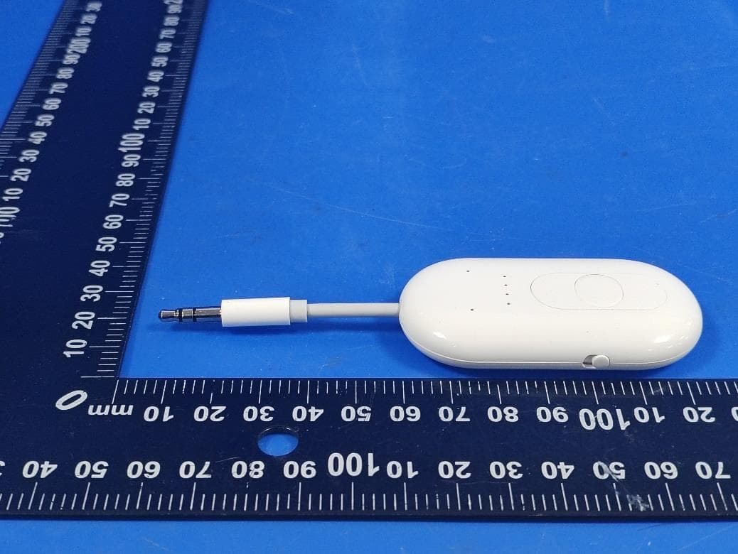
Click to zoom
Application Details
- Equipment Class
- DSS - Part 15 Spread Spectrum Transmitter
- Date of Grant
- Jan 29, 2026
- Application Purpose
- Original Equipment
- Equipment Note
- Bluetooth audio transceiver
- Frequency Range
- 2402.00000000 - 2480.00000000
- Country
- China
Documents & Files
Document Text
Text extracted from the exhibit documents filed with the FCC. Open a document above to read the original.
Users Manual
AudioFly Bluetooth Audio Transmitter / Receiver User Manual Version: v1.0 | Language: English © AudioFly. All rights reserved. 1. Overview AudioFly is a compact Bluetooth audio adapter designed to help you use wireless headphones with wired audio sources, and to stream audio from a phone wirelessly to a wired sound system. • TX (Transmit) mode: sends audio from a 3.5 mm headphone jack (airplane IFE, TV, treadmill, game console, etc.) to Bluetooth headphones/speakers. • RX (Receive) mode: receives audio from a phone/tablet via Bluetooth and outputs it to a 3.5 mm AUX input (car stereo, boat speakers, home audio, etc.). • Dual headphone sharing (Headphone 1 + Headphone 2): connect two Bluetooth headsets at the same time (TX mode). 2. What's in the Box Your AudioFly package typically includes: • AudioFly Bluetooth Adapter; • USB-A to USB-C Charging Cable; • International Airline Adapter (for dual-prong airplane jacks, if included in your package); • RCA male to 3.5mm female cable; • User Manual (may vary by package). 3. Product at a Glance Front view (see image on cover): Part / Control Description 3.5 mm plug Connects to a wired audio source (TX) or to an AUX input device (RX). Pairing indicator 1 Shows connection/status for the first paired headphone (TX mode). Pairing indicator 2 Shows connection/status for the second paired headphone (TX mode). Battery/Status LEDs (4 dots) Press any button, the Battery Satus LEDs Show battery level . Approx. 25% / 50% / 75% / 100% battery remaining Volume + Increase volume. Paring button Pair/Connect control; may be used for reset (see Section 6). Volume - Decrease volume. Power switch (side) Turns AudioFly on/off. TX/RX mode switch (side) Selects Transmitter (TX) or Receiver (RX) mode. USB-C charging port (side) Use a 5V USB power source to charge AudioFly. Note: Physical control layout may vary slightly by batch. If your unit differs, follow the icons on the device. 4. Charging Before first use, fully charge AudioFly. 1. Connect the included USB-A to USB-C cable to AudioFly and a 5V USB power source. 2. During charging, the status LEDs may animate to indicate progress. 3. When fully charged, the LEDs may turn solid or turn off (model dependent). Typical playtime is up to 30+ hours (usage and volume dependent). 5. Using AudioFly 5.1. TX Mode 5.2. TX Mode (Transmit: wired source -> Bluetooth headphones) 1. Set the side switch to TX. 2. Turn AudioFly ON. 3. Put your Bluetooth headphones (or speaker) into pairing mode (see your headphone's manual). 4. Press and hold the Paring button 2 second until the Pairing indicator 1 blinks rapidly. 5. When connected, the paring indicator 1 turns solid. 6. Plug AudioFly into the 3.5 mm headphone jack you want to listen to (airplane IFE, TV, treadmill, etc.). Adjust volume using the + / - buttons on AudioFly, your headphones, or the source device. 5.3. TX mode (Dual Headphone Sharing) To connect a second set of Bluetooth headphones: 1. Ensure your first headphones are already connected (the paring indicator solid). 2. Put the second headphones into pairing mode. 3. Press and hold the Pairing button again until the paring indicator blinks rapidly. 4. Wait for the paring indicator to turn solid to confirm connection. Tip: For best results, keep both headphones close to AudioFly during pairing. 5.4. RX Mode (Receive: phone -> wired AUX) 1. Set the side switch to RX. 2. Plug AudioFly into the AUX input device (car stereo, boat speaker system, home receiver, etc.). 3. Turn AudioFly ON. 4. Press and hold the pairing button to enter pairing mode (One of the Pairing indicator blinks rapidly). 5. On your phone/tablet, open Bluetooth settings and select “AudioFly”. Once connected, play audio on your phone. Use your phone to control playback and volume. 6. Button Shortcuts and Reset Shortcuts (may vary by firmware): Action Operation Result Enter pairing mode Press and hold pairing button ~2 seconds Headphone/Status indicator blinks Battery check Press Volume + Press Volume - Pairing button Battery LEDs light up to show remaining level Mute / Unmute(Only for RX mode) Double-press Pairing button Mutes/unmutes (device dependent) Factory reset Press and hold pairing button at least ~8 seconds Clears paired devices and restarts If you have pairing issues, perform a factory reset and pair again. 7. LED Indicators Common indicator meanings (may vary): Indicator Meaning Pairing indicator 1 blinking rapidly Pairing mode for Headphone 1 (TX mode) Pairing indicator 1 blinking Slowly Try to connect the pared Headphone (TX mode) Pairing indicator 1 solid Headphone 1 connected (TX mode) Pairing indicator 2 blinking rapidly Pairing mode for Headphone 2 (TX mode) Pairing indicator 2 blinking Slowly Try to connect the pared Headphone (TX mode) Pairing indicator 2 solid Headphone 2 connected (TX mode) 4-dot LEDs (1–4 lit) Approx. 25% / 50% / 75% / 100% battery remaining LEDs cycling while charging Charging in progress 8. Troubleshooting If AudioFly is not working as expected: • No sound (TX mode): Confirm AudioFly is in TX mode and fully inserted into the headphone jack. Make sure your headphones are connected (indicator solid). Try increasing volume on AudioFly and on the headphones. • No sound (RX mode): Confirm AudioFly is in RX mode and plugged into an AUX input (not a microphone jack). Check the car/home system is set to AUX. Confirm your phone is connected to “AudioFly”. • Cannot pair: Turn Bluetooth “OFF/ON” on, on your headphones/phone. Reset AudioFly (Section 6) and try pairing again. Keep devices within 1 meter during pairing. • Audio cuts out: Reduce distance and remove obstacles. Avoid placing AudioFly next to strong Wi‑Fi routers or microwave ovens. Low battery can also cause dropouts. • Low volume: Some in‑flight systems have low output. Increase volume on the source device if possible, or adjust volume on your headphones. Press the Volume + button on the AudioFly. 9. Specifications Bluetooth version 5.3 Supported profiles A2DP / AV…
Text truncated - open the document above for the full version.
Attestation Statements
Rev 1/26/2023 Smlpretty Technology Co.,Ltd Federal Communications Commission Authorization and Evaluation Division 7435 Oakland Mills Road Columbia, MD 21046 USA Date: 2026-01-26 FCC ID: 2AOSJ-AUDIOFLY Ref. #1: Attestation Statements Part 2.911(d)(5)(i) Filing Smlpretty Technology Co.,Ltd certifies that the equipment for which authorization is sought is not “covered” equipment prohibited from receiving an equipment authorization pursuant to section 2.903 of the FCC rules. Smlpretty Technology Co.,Ltd certifies that the equipment for which authorization is sought does not include cybersecurity or anti-virus software produced or provided by Kaspersky Lab, Inc. or any of its successors and assignees, including equipment with integrated Kaspersky Lab, Inc. (or any of its successors and assignees) cybersecurity or anti-virus software pursuant to DA-24-886 and KDB 986446 D01 Covered Equipment Guidance section B(2a). Device is inherently compliant based on hardware limitations or software controls. or A Software Bill of Materials (SBOM) is provided to the TCB for review, and The end-user or third parties cannot install additional software on this device. Ref. #2: Attestation Statements Part 2.911(d)(5)(ii) Filing Smlpretty Technology Co.,Ltd certifies that, as of the date of the filing of the application, the applicant is not identified on the Covered List (as a specifically named entity or any of its subsidiaries or affiliates) as an entity producing “covered” equipment. pplicant: Smlpretty Technology Co.,Ltd Address: Unit 4J, Block B, Central, Xixiang Town, Bao’an District, Shenzhen, China Contact Person: Peter Zhang Tel.: +8618682028871 Email: [email protected] Sincerely, Signature:
Attestation Statements
Smlpretty Technology Co.,Ltd Unit 4J, Block B, Central, Xixiang Town, Bao’an District, Shenzhen, China U.S. Agent Letter of Attestation To: Federal Communications Commission 7435 Oakland Mills Road, Columbia, MD 21046, USA Date: Jan. 27, 26 Ref: Attestation Statement – Part 2.911(d)(7) filing FCC ID: [2AOSJ-AUDIOFLY] [Smlpretty Technology Co.,Ltd] (“the applicant”) certifies that, as of the date of the filing of the application, [HOPEK CORPORATION INC] (“the agent”) is our designated U.S. agent for service of process for the above reference FCC ID. The applicant accepts to maintain an agent for service of process in the United States for no less than one year after either the grantee has permanently terminated all marketing and importation of the applicable equipment within the U.S., or the conclusion of any Commission-related administrative or judicial proceeding involving the equipment, whichever is later. The applicant further acknowledges it is our responsibility to inform the FCC whenever the agent information changes. [HOPEK CORPORATION INC] ("the agent) understand it is the agent's obligation to accept service of process in the United States for matters related to the applicable equipment, and at the physical U.S. address and email address. Designated U.S. Agent Company Name: HOPEK CORPORATION INC FRN: 0034562900 Address: 16755 Coyote Bush Dr Unit 84, San Diego, CA 92127 United States Signature: Contact Person: Peter Davis Tel: 561-235-6113 Email: [email protected] Applicant Company Name: Smlpretty Technology Co.,Ltd FRN: 0027142736 Address: Unit 4J, Block B, Central, Xixiang Town, Bao’an District, Shenzhen, China Signature: Contact Person: Peter Zhang Tel: +8618682028871 Email: [email protected]
Cover Letter(s)
2.4GHz 3216 Chip Antenna: RAN3216F6P2G45 ______________________________________________________________________________________________________ Application: WLAN, 802.11b/g, Bluetooth, etc... Features SMD, high reliability, ultra Impact, Omni-directional... Part number RAN 3216 - F6 (1) (2) (3) P 2G45 (4) (5) (1)Product Type Chip Antenna (2)Size Code 3.2x1.6mm (3)Type Code F6 (4)Packing Paper Tape (5)Frequency 2.45GHz Electrical Specification W orking Frequency Range 2400 ~2484 MHz Peak Gain 2.58 dBi (Typ.) Impedance 50 Ohm Return loss 10 dB ( Min) Polarization Linear Azimuth Beamwidth Omni-directional Operation Temperature(°C) -40 ~85°C The specification is defined on EVB. Dimension and Terminal Configuration Dimension (mm) No. Terminal Name L 3.15+-0.15 1 Feeding point W 1.55+-0.15 2 GND T 0.50+-0.10 A 0.35+-0.10 Manufacturer:ÿSmlpretty Technology Co.,Ltd Address:ÿUnit 4J, Block B, Central, Xixiang Town, Bao'an District, Shenzhen, China 2.4GHz 3216 Chip Antenna: RAN3216F6P2G45 ______________________________________________________________________________________________________ Evaluation Board Reference PCB Dimension Antenna Layout Reference unit :mm Electrical Characteristics Return Loss & Radiation Return Loss Frequency (MHz) (dB) 2000 10 2092 23.5 215510 Radiation Return Loss 2.4GHz 3216 Chip Antenna: RAN3216F6P2G45 ______________________________________________________________________________________________________ Taping Specifications Reel and Taping Specification Reel Specification TYPE SIZE A ψB ψC ψD W ψM 3216 7” 5K/Reel 2.0±0.5 13.5±1.0 21±1.0 60±1.0 11.5±2.0 178±2.0 Tapping Specification Packaging Type A B W E F G H T ψD P Paper Type 3216 1.90±0.20 3.50±0.20 8.0±0.20 1.75±0.10 3.5±0.05 4.0±0.10 2.0±0.05 0.75±0.10 +0.10 1.50 -0 4.0±0.1 2.4GHz 3216 Chip Antenna: RAN3216F6P2G45 ______________________________________________________________________________________________________ Reliability Table Test ItemProcedure Requirements Ceramic Type Remark (Reference) Electrical Characterization Fulfill the electrical specification User Spec. Thermal Shock 1. Preconditioning: 50 ± 10°C / 1 hr , then keep for 24 ± 1 hrs at room temp. 2. Initial measure: Spec: refer Initial spec. 3. Rapid change of temperature test: -30°C to +85°C; 100 cycles; 15 minutes at Lower category temperature; 15 minutes at Upper category temperature. No Visible Damage. Fulfill the electrical specification. MIL-STD-202 107 Temperature Cycling 1. Initial measure: Spec: refer Initial spec. 2. 100 Cycles (-30°C to +85°C), Soak Mode=1 (2 Cycle/hours). 3. Measurement at 24 ± 2Hours after test condition. No Visible Damage. Fulfill the electrical specification. JESD22 JA104 High Temperature Exposure 1. Initial measure: Spec: refer Initial spec. 2. Unpowered; 500hours @ T=+85°C. 3. Measurement at 24 ± 2 hours after test. No Visible Damage. Fulfill the electrical specification. MIL-STD-202 108 Low Temperature Storage 1. Initial measure: Spec: refer Initial spec. 2. Unpowered: 500hours @ T= -30°C. 3. Measurement at 24 ± 2 hours after test. No Visible Damage. Fulfill the electrical specification. MIL-STD-202 108 Solderability (SMD Bottom Side) Dipping method: a. Temperature: 235 ± 5°C b. Dipping time: 3 ± 0.5s The solder should cover over 95% of the critical area of bottom side. IEC 60384-21/22 4.10 Soldering Heat Resistance (RSH) Preheating temperature: 150 ± 10°C. Preheating time: 1~2 min. Solder temperature: 260 ± 5°C. Dipping time: 5 ± 0.5s No Visible Damage.IEC 60384-21/22 4.10 Vibration5g's for 20 min., 12 cycles each of 3 orientations Note: Use 8"X5" PCB .031" thick 7 secure points on, one long side and 2 secure points at corners of opposite sides. Parts mounted within 2" from any secure point. Test from 10-2000 Hz. No Visible Damage.MIL-STD-202 Method 204 Mechanical Shock Three shocks in each direction shall be applied along the three mutually perpendicular axes of the test specimen (18 shocks) Peak value: 1,500g’s Duration: 0.5ms Velocity change: 15.4 ft/s Waveform: Half-sine No Visible Damage.MIL-STD-202 Method 213 Humidity Bias 1. Humidity: 85% R.H., Temperature: 85 ± 2 °C. 2. Time: 500 ± 24 hours. 3. Measurement at 24 ± 2hrs after test condition. No Visible Damage. Fulfill the electrical specification. MIL-STD-202 Method 106 2.4GHz 3216 Chip Antenna: RAN3216F6P2G45 ______________________________________________________________________________________________________ Revision History Revision Date Content 1 2020/7/20New issue Board Flex (SMD) 1. Mounting method: IR-Reflow. PCB Size (L:100 × W:40 × T:1.6mm) 2. Apply the load in direction of the arrow until bending reaches 2 mm. No Visible Damage.AEC-Q200 005 AdhesionForce of 1.8Kg for 60 seconds.No Visible Damage Magnification of 20X or greater may be employed for inspection of the mechanical integrity of the device body terminals and body/terminal junction. AEC-Q200 006 Physical Dimension Any applicable method using x10 magnification, micrometers, calipers, gauges, contour projectors, or other measuring equipment, capable of determining the actual specimen dimensions. In accordance with specification. JESD22 JB100
Cover Letter(s)
Smlpretty Technology Co.,Ltd Office of Engineering Technology Federal Communications Commission 7435 Oakland Mills Road Columbia, MD 21046 USA Date: January 28, 2026 Subject; Request for Confidentiality FCC ID: 2AOSJ-AUDIOFLY To Whom It May Concern, Pursuant to the provisions of the Commission’s rules Title 47 Sections §0.457 and §0.459, we are requesting the Commission to withhold the following attachment(s) as confidential documents from public disclosure indefinitely. These documents contain detailed system and equipment descriptions and are considered as proprietary information in operation of the equipment. The public disclosure of these documents might be harmful to our company and would give competitors an unfair advantage in the market. Schematic Diagram Block Diagram Parts List Operational Description Tune-up Procedure SOFTWARE SECURITY REQUIREMENTS FOR U-NII DEVICES In additional to above mentioned documents, in order to comply with the marketing regulations in Title 47 CFR §2.803 and the importation rules in Title 47 CFR §2.1204, while ensuring that business sensitive information remains confidential until the actual marketing of newly authorized devices, we request Short Term Confidentiality of the following attachment(s); External Photos Test Setup Photos Internal Photos User Manual For 45 days, pursuant to Public Notice DA 04-1705. OR For 180 days pursuant to KDB 726920 D01. It is our understanding that all measurement test reports, FCC ID label format and correspondence during the certification review process cannot be granted as confidential documents and this information will be available for public review once the grant of equipment authorization is issued. Sincerely, Signature: Name: Peter Zhang Title: General manager
Cover Letter(s)
Effective Date: April 2, 2020 QSF 7.6.4-8 – Agent Authorization Letter Template Page 1 of 1 Revision Date: Revision: 0 Smlpretty Technology Co.,Ltd Date:2026-01-26 Product Model Number: AudioFly ; FCC ID:2AOSJ-AUDIOFLY To whom it may concern, Re: Product Certification Representative Authorization Letter We authorize QAI Laboratories Ltd. 3980 North Fraser Way, Burnaby B.C. Canada V5J 5K5 to act on our behalf on all matters concerning the above named equipment. This shall include the following: • Testing • Approval applications and procedures We declare that QAI Laboratories Ltd. is allowed to forward all information related to the approval project to the applied certification body and to the notification entities and to discuss any issues concerning the approval application. Any and all acts carried out by QAI Laboratories Ltd. on our behalf shall have the same effect as acts of our own. Signature: By: Peter Zhang Contact Listed on FCC Wesbite Title: General manager Email: [email protected] On behalf of: Smlpretty Technology Co.,Ltd
External Photos
Page 1 of 3 Report No.: LGT26A099 Appendix - External Photographs of EUT Constructional Details Photo 1 Photo 2 Page 2 of 3 Report No.: LGT26A099 Appendix - External Photographs of EUT Constructional Details Photo 3 Photo 4 Page 3 of 3 Report No.: LGT26A099 Appendix - External Photographs of EUT Constructional Details Photo 5 Photo 6
Internal Photos
Page 1 of 3 Report No.: LGT26A099 Appendix - Internal Photographs of EUT Constructional Details Photo 1 Photo 2 Page 2 of 3 Report No.: LGT26A099 Appendix - Internal Photographs of EUT Constructional Details Photo 3 Photo 4 Page 3 of 3 Report No.: LGT26A099 Appendix - Internal Photographs of EUT Constructional Details Photo 5 Photo 6 ANT
RF Exposure Info
The test report is effective only with both signature and specialized stamp. This report shall not be reproduced except in full without the written approval of the Laboratory. The results in this report only apply to the tested sample. Shenzhen LGT Test Service Co., Ltd. Tel: 0755-89668180 E-mail:[email protected] Web: www.lgt-cert.com Room 205, Building 13, Zone B, Zhenxiong Industrial Park, No.177, Renmin West Road, Jinsha, Kengzi Street, Pingshan District, Shenzhen, Guangdong, China Page 1 of 8 EMF TEST REPORT Product Name: Bluetooth audio transceiver Model Number: AudioFly FCC ID: 2AOSJ-AUDIOFLY Issued For : Smlpretty Technology Co.,Ltd Unit 4J, Block B, Central, Xixiang Town, Bao'an District, Shenzhen, China Issued By : Shenzhen LGT Test Service Co., Ltd. Room 205, Building 13, Zone B, Zhenxiong Industrial Park, No.177, Renmin West Road, Jinsha, Kengzi Street, Pingshan District, Shenzhen, Guangdong, China Report Number: LGT26A099HA01 Sample Received Date: Jan. 14, 2026 Date of Test: Jan. 14, 2026 ~ Jan. 23, 2026 Date of Issue: Jan. 23, 2026 Report No.: LGT26A099HA01 Page 2 of 8 TEST REPORT CERTIFICATION Applicant: Smlpretty Technology Co.,Ltd Address: Unit 4J, Block B, Central, Xixiang Town, Bao'an District, Shenzhen, China Manufacturer: Smlpretty Technology Co.,Ltd Address: Unit 4J, Block B, Central, Xixiang Town, Bao'an District, Shenzhen, China Product Name: Bluetooth audio transceiver Trademark: LOCCESS Model Number: AudioFly Sample Status: Normal APPLICABLE STANDARDS STANDARD TEST RESULTS FCC 47 CFR §2.1093 KDB 447498 D01 General RF Exposure Guidance v06 PASS Prepared by: Approved by: Zane Shan Vita Li Engineer Technical Director Report No.: LGT26A099HA01 Page 3 of 8 TABLE OF CONTENTS 1 . GENERAL INFORMATION 5 1.1 GENERAL DESCRIPTION OF THE EUT 5 1.2 TEST LABORATORY 5 2 . FCC 47CFR §2.1093 REQUIREMENT 6 2.1 TEST STANDARDS 6 2.2 LIMIT 6 2.3 TEST RESULT 8 Report No.: LGT26A099HA01 Page 4 of 8 Revision History Rev. Issue Date Revisions 00 Jan. 23, 2026 Initial Issue Report No.: LGT26A099HA01 Page 5 of 8 1. GENERAL INFORMATION 1.1 GENERAL DESCRIPTION OF THE EUT Product Name: Bluetooth audio transceiver Test Model Number: AudioFly Series Number: N/A Model Difference: N/A Frequency Bands: Bluetooth 2402 – 2480MHz Rating: Input: DC 5V 220mA Battery: Rated Voltage: 3.7V Hardware Version: N/A Software Version: N/A 1.2 TEST LABORATORY Company Name: Shenzhen LGT Test Service Co., Ltd. Address: Room 205, Building 13, Zone B, Zhenxiong Industrial Park, No.177, Renmin West Road, Jinsha, Kengzi Street, Pingshan District, Shenzhen, Guangdong, China Accreditation Certificate: FCC Registration No.: 746540 CAB ID: CN0136 Report No.: LGT26A099HA01 Page 6 of 8 2. FCC 47CFR §2.1093 REQUIREMENT 2.1 TEST STANDARDS The limit for Maximum Permissible Exposure (MPE) specified in KDB 447498 D01 General RF Exposure Guidance v06 is followed. The gain of the antennas used in the product is extracted from the Antenna data sheets provided and also the maximum total power input to the antenna is measured. Through the Friis transmission formula and the maximum gain of the antenna, we can calculate the distance, away from the product, where the limit of MPE is reached. Although the Friis Transmission formula is far field assumption, the calculated result of that is an over-prediction for near field power density. It is taken as worst case to specify the safety range. 2.2 LIMIT Approximate SAR Test Exclusion Power Thresholds at Selected Frequencies and Test Separation Distances are illustrated in the following Table. Report No.: LGT26A099HA01 Page 7 of 8 The 1-g and 10-g SAR test exclusion thresholds for 100 MHz to 6 GHz at test separation distances ≤ 50 mm are determined by: [(max. power of channel, including tune-up tolerance, mW)/(min. test separation distance, mm)] • [√f(GHz)] ≤ 3.0 for 1-g SAR and ≤ 7.5 for 10-g extremity SAR,where f(GHz) is the RF channel transmit frequency in GHz. Power and distance are rounded to the nearest mW and mm before calculation The result is rounded to one decimal place for comparison The test exclusions are applicable only when the minimum test separation distance is ≤ 50 mm and for transmission frequencies between 100 MHz and 6 GHz. When the minimum test separation distance is < 5 mm, a distance of 5 mm is applied to determine SAR test exclusion. Report No.: LGT26A099HA01 Page 8 of 8 2.3 TEST RESULT Turn up Result Mode Turn up Power BT-GFSK 0±1dBm BT-π/4-DQPSK 1.5±1dBm BT-8DPSK 2±1dBm The MPE result of worst mode: RF Function Frequency (MHz) Max Turn up Power (dBm) Max Turn up Power (mW) Estimated SAR Limit Ratio Result BT 2480 3.00 2.00 0.628 3 0.209 Pass Note: 1. The Maximum Power Density is less than the limit, complies with the exemption requirements. ※※※※※END OF THE REPORT※※※※※
Test Report
The test report is effective only with both signature and specialized stamp. This report shall not be reproduced except in full without the written approval of the Laboratory. The results in this report only apply to the tested sample. Shenzhen LGT Test Service Co., Ltd. Tel: 0755-89668180 E-mail:[email protected] Web: www.lgt-cert.com Room 205, Building 13, Zone B, Zhenxiong Industrial Park, No.177, Renmin West Road, Jinsha, Kengzi Street, Pingshan District, Shenzhen, Guangdong, China Page 1 of 74 RF TEST REPORT Product Name: Bluetooth audio transceiver Model Number: AudioFly FCC ID: 2AOSJ-AUDIOFLY Issued For : Smlpretty Technology Co.,Ltd Unit 4J, Block B, Central, Xixiang Town, Bao'an District, Shenzhen, China Issued By : Shenzhen LGT Test Service Co., Ltd. Room 205, Building 13, Zone B, Zhenxiong Industrial Park, No.177, Renmin West Road, Jinsha, Kengzi Street, Pingshan District, Shenzhen, Guangdong, China Report Number: LGT26A099RF01 Sample Received Date: Jan. 14, 2026 Date of Test: Jan. 14, 2026 ~ Jan. 23, 2026 Date of Issue: Jan. 23, 2026 Report No.: LGT26A099RF01 Page 2 of 74 TEST REPORT CERTIFICATION Applicant: Smlpretty Technology Co.,Ltd Address: Unit 4J, Block B, Central, Xixiang Town, Bao'an District, Shenzhen, China Manufacturer: Smlpretty Technology Co.,Ltd Address: Unit 4J, Block B, Central, Xixiang Town, Bao'an District, Shenzhen, China Product Name: Bluetooth audio transceiver Trademark: LOCCESS Model Number: AudioFly Sample Status: Normal APPLICABLE STANDARDS STANDARD TEST RESULTS FCC Part 15.247, Subpart C ANSI C63.10-2020 PASS Prepared by: Approved by: Zane Shan Vita Li Engineer Technical Director Report No.: LGT26A099RF01 Page 3 of 74 Table of Contents Page 1. SUMMARY OF TEST RESULTS 6 1.1 TEST LABORATORY 7 1.2 MEASUREMENT UNCERTAINTY 7 2. GENERAL INFORMATION 8 2.1 GENERAL DESCRIPTION OF THE EUT 8 2.2 DESCRIPTION OF THE TEST MODES 10 2.3 FREQUENCY HOPPING SYSTEM REQUIREMENTS 10 2.4 TABLE OF PARAMETERS OF TEST SOFTWARE SETTING 12 2.5 DESCRIPTION OF NECESSARY ACCESSORIES AND SUPPORT UNITS 12 2.6 EQUIPMENTS LIST 13 3. EMC EMISSION TEST 15 3.1 CONDUCTED EMISSION MEASUREMENT 15 3.2 RADIATED EMISSION MEASUREMENT 19 4. CONDUCTED SPURIOUS & BAND EDGE EMISSION 30 4.1 LIMIT 30 4.2 TEST PROCEDURE 30 4.3 TEST SETUP 30 4.4 EUT OPERATION CONDITIONS 31 4.5 TEST RESULTS 31 5. NUMBER OF HOPPING CHANNEL 32 5.1 LIMIT 32 5.2 TEST PROCEDURE 32 5.3 TEST SETUP 32 5.4 EUT OPERATION CONDITIONS 32 5.5 TEST RESULTS 32 6. AVERAGE TIME OF OCCUPANCY 33 6.1 LIMIT 33 6.2 TEST PROCEDURE 33 6.3 TEST SETUP 33 6.4 EUT OPERATION CONDITIONS 33 6.5 TEST RESULTS 33 7. HOPPING CHANNEL SEPARATION MEASUREMEN 34 7.1 LIMIT 34 7.2 TEST PROCEDURE 34 Report No.: LGT26A099RF01 Page 4 of 74 7.3 TEST SETUP 34 7.4 EUT OPERATION CONDITIONS 34 7.5 TEST RESULTS 34 8. BANDWIDTH TEST 35 8.1 LIMIT 35 8.2 TEST PROCEDURE 35 8.3 TEST SETUP 35 8.4 EUT OPERATION CONDITIONS 35 8.5 TEST RESULTS 35 9. OUTPUT POWER TEST 36 9.1 LIMIT 36 9.2 TEST PROCEDURE 36 9.3 TEST SETUP 36 9.4 EUT OPERATION CONDITIONS 36 9.5 TEST RESULTS 36 10. ANTENNA REQUIREMENT 37 10.1 STANDARD REQUIREMENT 37 10.2 EUT ANTENNA 37 APPENDIX I - TEST RESULTS 38 1. DUTY CYCLE 38 2. BANDWIDTH 42 3. MAXIMUM CONDUCTED OUTPUT POWER 49 4. CARRIER FREQUENCY SEPARATION 53 5. NUMBER OF HOPPING FREQUENCIES 55 6. TIME OF OCCUPANCY (DWELL TIME) 57 7. UNWANTED EMISSIONS IN NON-RESTRICTED FREQUENCY BANDS 60 APPENDIX II - MEASUREMENT PHOTOS 74 Report No.: LGT26A099RF01 Page 5 of 74 Revision History Rev. Issue Date Revisions 00 Jan. 23, 2026 Initial Issue Report No.: LGT26A099RF01 Page 6 of 74 1. SUMMARY OF TEST RESULTS Test procedures according to the technical standards: KDB 558074 D01 15.247 Meas Guidance v05r02. FCC Part 15.247, Subpart C Standard Section Test Item Judgment Remark 15.207 Conducted Emission PASS -- 15.247(a)(1) Hopping Channel Separation PASS -- 15.247(a)(1)&(b)(1) Output Power PASS -- 15.209 Radiated Spurious Emission PASS -- 15.247(d) Conducted Spurious & Band Edge Emission PASS -- 15.247(a)(1)(iii) Number of Hopping Frequency PASS -- 15.247(a)(1)(iii) Dwell Time PASS -- 15.247(a)(1) Bandwidth PASS -- 15.205 Restricted bands of operation PASS -- Part 15.247(d)/part 15.209(a) Band Edge Emission PASS -- 15.203 Antenna Requirement PASS -- NOTE: (1) ‘N/A’ denotes test is not applicable in this Test Report. (2) All tests are according to ANSI C63.10-2020. Report No.: LGT26A099RF01 Page 7 of 74 1.1 TEST LABORATORY Company Name: Shenzhen LGT Test Service Co., Ltd. Address: Room 205, Building 13, Zone B, Zhenxiong Industrial Park, No.177, Renmin West Road, Jinsha, Kengzi Street, Pingshan District, Shenzhen, Guangdong, China Accreditation Certificate: FCC Registration No.: 746540 CAB ID: CN0136 1.2 MEASUREMENT UNCERTAINTY The reported uncertainty of measurement y ± U, where expended uncertainty U is based on a standard uncertainty multiplied by a coverage factor of k=2, providing a level of confidence of approximately 95 %. No. Item Uncertainty 1 Occupied Channel Bandwidth ±0.46% 2 RF Output Power, Conducted ±0.71dB 3 Power Spectral Density, Conducted ±1.57dB 4 Unwanted Emission, Conducted ±0.63dB 5 Conducted emission ±2.80dB 6 All Emissions, Radiated (0.009-30MHz) ±2.16dB 7 All Emissions, Radiated (30MHz-1GHz) ±4.61dB 8 All Emissions, Radiated (1GHz-18GHz) ±5.49dB 9 Temperature ±0.5∞C 10 Humidity ±2% 11 Duty Cycle ±2.3% Note: The measurement uncertainty is not included in the test result. Report No.: LGT26A099RF01 Page 8 of 74 2. GENERAL INFORMATION 2.1 GENERAL DESCRIPTION OF THE EUT Product Name: Bluetooth audio transceiver Test Model Number: AudioFly Series Number: N/A Model Difference: N/A Channel List: Please refer to the Note 3. Bluetooth: Frequency:2402 – 2480 MHz Modulation: GFSK(1Mbps), π/4-DQPSK(2Mbps), 8DPSK(3Mbps) Antenna Type: Chip Antenna Antenna Gain: 2.58dBi Rating: Input: DC 5V 220mA Battery: Rated Voltage: 3.7V Hardware Version: N/A Software Version: N/A Connecting I/O Port(s): Please refer to the Note 1. Note: 1. For a more detailed features descrip…
Text truncated - open the document above for the full version.
Test Setup Photos
Page 1 of 2 Report No.: LGT26A099 Appendix - Test Setup photos Set-up for Radiated Spurious Emission, Below 1GHz Set-up for Radiated Spurious Emission, Above 1GHz Page 2 of 2 Report No.: LGT26A099 Set-up for Conducted Emission
Contact Information
Applicant
Peter Zhang
[email protected]Fax: 0755-23280482
Technical Contact
Test Firm
Shenzhen LGT Test Service Co., Ltd.Wen Wen
Technical Specifications
| # | Rule Parts | Frequency Range | Power Output |
|---|---|---|---|
| 1 | 15C | 2.40 GHz - 2.48 GHz | 1.96 mW |
Other Applications from Smlpretty Technology Co., Ltd
2AOSJ-EKPL2
Aug 26, 2024BLE Smart Padlock
Equipment Class
DTS - Digital Transmission System2AOSJ-SMKB2-FP
Aug 26, 2024Smart BLE Fingerprint Key box
Equipment Class
DTS - Digital Transmission System