2AOTU-KDDY109B-XXXControl box
Changzhou Kaidi Electrical Inc.
Click to zoom
Application Details
- Equipment Class
- DXX - Part 15 Low Power Communication Device Transmitter
- Date of Grant
- Jan 07, 2023
- Application Purpose
- Original Equipment
- Date of Application
- Jan 07, 2023
- Equipment Note
- Control box
- Frequency Range
- 2402.00000000 - 2402.00000000
- Country
- China
Documents & Files
Document Text
Text extracted from the exhibit documents filed with the FCC. Open a document above to read the original.
Users Manual
1 KDDY109B + KDH243B one control two control system function manual I、 System connection diagram II、 Product list The serial number Name (code name) Model and Specificatio n Num ber note 1 Hand control device KDH243 1 2 Control box KDDY109 1 3 Power supply box KDDY01B 1 4 Push Rod 1 (H) KDYJT014 1 5 Push Rod 2 (F) KDYJT014 1 6 Lamp with DY056 1 7 Vibrating motor ZYD060 2 III、 Performance Parameters 1. Control box performance parameters: Input voltage AC 110‐240V 50/60Hz Rated output (single channel) 29V DC/ 5A (10% work system, maximum 2 minutes of continuous work and 18 minutes of stop) 2. Manual controller performance parameters: Input voltage 4.5V Number of keys 14 2 Outline of KDDY109B Outline of H243B 3 IV、Manual controller key function description 4 1、 Function of hand control device: The serial number name function note 1 Preset position 1, K1 light touch press, the push rod running to a fixed position (Leisure mode) stop (head push rod travel: 42mm, leg push rod travel: 43mm). 2. Press K2 gently and stop the push rod running to a fixed position (Incline tilt mode) (head push rod travel: 48mm, leg push rod travel: 32mm) 3. Press K5 gently and stop the push rod running to a fixed position (zero gravity mode) (head push rod travel: 23mm, leg push rod travel: 37mm) 4, K6 touch press, the putter does not move. 5. K10 gently presses the push rod to a fixed position (Anti- Snore mode) and stops (head push rod stroke: 18mm, leg push rod stroke: 0mm). 1、 Press any key to stop the push rod during operation; 2、 Perform the head putt first, then the leg putt 2 Place of memory Press and hold 6+1/6+2/6+5/6+10 at the same time. After the backlight 1、 The position can be modified by the customer according to 5 flashes for 3 seconds, the control box will remember the current position of the push rod; At the same time, the buzzer buzzes once and the backlight is off. Press K1, K2, K10 or K5 again, and the push rod will run to the corresponding memory position; the itinerary after delivery; Hold down 6+1/6+2/6+5/6+10 for 3S to remember the current position (overwriting the previous position); At the same time, the control box buzzes once and the backlight flashes three times. 2、 Press any key to stop the push rod during operation; 3 Push bar 1 (head bar H) lift Press K3, push rod out, release will stop; Press K4, push rod retract, release will stop; 4 Putter 2 (leg putter F) lift Press K7, push rod out, release will stop; Press K8, push rod retract, release will stop; 5 Putt 1 and putt 2 (head and leg) fall together 1. Long press K9 and pull back putter 1 and putter 2 at the same time after 3S; 2. During the operation of the push rod, you can release the key (Note: press any key and the push 1. Short press is invalid 2. During the operation of the push rod, press any key to stop the push rod, except Flat(K9) and Frogram (K6). 6 rod will stop, except Flat (9) and Frogram (6). 6 Vibration mode switching and vibration intensity selection 1, short press K14, each vibration mode switch starts from 1,123 cycle in turn;(Note: The corresponding indicator light is highlighted) 2, long press K14, vibration mode automatically switch (1S at each interval), release will stop, to stay in the current gear vibration mode operation; Mode 1: intermittent vibration with a slower frequency; Mode 2: intermittent vibration with higher frequency; Mode 3: intermittent vibration with the fastest frequency; The three modes are switched sequentially; If the change button is not operated within 15 minutes, the vibrating motor will automatically shut down (select the motor strength for the last time and start to calculate the time). 7 3、 Short press K12, vibration motor enhancement (intensity is divided into four gears), each time press gradually strengthen. The vibration motor can be opened by the rise button of the vibration motor (12) or by pressing the vibration mode (14) (Note: the 7 4、 Short press K13, the vibration motor weakens (the strength is divided into four gears), and gradually decreases with each press, and the motor stops with the fourth press. 5、 Short press K11 to stop the vibrating motor. intensity of the vibration motor is in gear 3 at this time). 8 Lamp with K15 Gently press (the button on the back of the hand controller), and the light belt will turn on. Press it again, and the light belt will turn off. 9 pairing Method 1: Long press the pairing button of the control box for 3 seconds to enter the pairing state; Press the hand controller K3 and K7 within 15 seconds, hold for 3 seconds, the control box buzzes once, the pairing button stops blinking, and the background light of the hand controller flashes for 3 times, the pairing is successful; 8 Method 2: Power on the control box again after 5 seconds of power failure, and the control box enters the pairing state; Press the hand controller K3 and K5 within 15 seconds, hold for 3 seconds, the control box buzzes once, the pairing button stops blinking, and the background light of the hand controller flashes three times, the pairing is successful; 10 Clearing matches Method 1: Long press the pairing button of the control box for 3 seconds to enter the pairing state; Press the hand controller K4 and K8 within 15 seconds and hold for 3 seconds. The control box buzzes once, the pairing button stops blinking, and the background light of the hand controller flashes for 3 times. The pairing is successful. Method 2: Power on the 9 control box again after 5 seconds of power failure, and the control box enters the pairing state; Press the hand controller K4 and K8 within 15 seconds and hold for 3 seconds. The control box buzzes once, the pairing button stops blinking, and the background light of the hand controller flashes for 3 times. The pairing is successful. 11 factory data reset Method 1: Long press the pairing button of the control box for 3 seconds to enter the pairing state; Press the hand controller K3 and K8 within 15 seconds and hold for 3 seconds. The cont…
Text truncated - open the document above for the full version.
Cover Letter(s)
(Changzhou Kaidi Electrical Inc.) Federal Communications Commission Authorization and Evaluation Division Confidentiality Request regarding application for certification of FCC ID: 2AOTU- KDDY109B- XXX Pursuant to Sections 0.457 and 0.459 of the Commission’s Rules, we hereby request confidential treatment of information accompanying this application as outlined below: Exhibit Type File Name Block Diagram, Schematics, Operational Description Block Diagram.pdf, Schematics.pdf, Operational Description.pdf The above materials contain trade secrets and proprietary information not customarily released to the public. The public disclosure of these materials may be harmful to the applicant and provide unjustified benefits to its competitors. The applicant understands that pursuant to Section 0.457 of the Rules, disclosure of this application and all accompanying documentation will not be made before the date of the Grant for this application. Pursuant to DA04-1705 June 15, 2004 of the Commission’s public notice, we also request temporary confidential treatment of information accompanying this application, Short-Term Confidentiality for 180 days as outlined below: Exhibit Type File Name External Photos, Test Setup Photos, Manual Test Setup Photos.pdf, Manual.pdf, External Photos.pdf Sincerely, Qin Yin/Manager Changzhou Kaidi Electrical Inc.
Cover Letter(s)
Difference Statement FCC ID: 2AOTU-KDDY109B-XXX KDDY109B-XXX The first “X” means the function, including order of going up and down, with or without LED light, color of LED light. The second "“X” means color of appearance. The third “X” means length of appliance lead wire. The only difference between the models in each series is the nomenclature. The PCB schematic diagram, PCB Layout, appearance, etc. are all the same. We prepared model KDDY109B-001 for RF test. Qin Yin/Manager Changzhou Kaidi Electrical Inc.
Cover Letter(s)
(Changzhou Kaidi Electrical Inc.) Federal Communications Commission Authorization and Evaluation Division 1435 Oakland Mills Road Columbia, MD 21046 Date: November 14, 2022 SUBJECT: FCC Application for FCC ID: 2AOTU- KDDY109B-XXX To Whom It May Concern: We, the undersigned, hereby authorize Tony Wei at EMTEK(NINGBO) CO., LTD. on our behalf, to apply to the Federal Communications Commission on our equipment. Any and all acts carried out by EMTEK(NINGBO) CO., LTD. on our behalf shall have the same effect as acts of our own. This is to advise that we are in full compliance with the Anti- Drug Abuse Act. We, the applicant, are not subject to a denial of federal benefits pursuant to Section 5301 of the Anti-Drug Act of 1988, 21 USC853a, and no party to the application is subject to a denial of federal benefits pursuant to that section. Sincerely, Qin Yin/Manager Changzhou Kaidi Electrical Inc.
External Photos
External photos: ---The End---
ID Label/Location Info
Label Location Model:KDDY109B‐XXX FCC ID: 2AOTU‐ KDDY109B‐XXX Contains Transmitter Module FCC ID: 2AQV6RABBIT
Internal Photos
Internal photos: 2.4G SRD PCB Antenna ---The End--- Bluetooth PCB Antenna
Test Report
Manufacturer : CHANGZHOU KAIDI ELECTRICAL INC Address : JiangCun, Henglin Town, Changzhou City, Jiangsu Province, China Model Name : KDH243B-XXX Antenna Gain : 1.0 dBi
Test Report
Report No.EDG2209270044E00501R Page 1 of 28 Ver.1.0 TEST REPORT Product Name : Control box Model Number : KDDY109B-XXX FCC ID : 2AOTU-KDDY109B-XXX $二维码$ Prepared for : Changzhou Kaidi Electrical Inc. Address : JiangCun, Henglin Town, Changzhou, China Prepared by : EMTEK (DONGGUAN) CO., LTD. Address : -1&2F., Building 2, Zone A, Zhongda Marine Biotechnology Research and Development Base, No. 9, Xincheng Avenue, Songshanhu High-technology Industrial Development Zone, Dongguan, Guangdong, China Tel : +86-0769-22807078 Fax: +86-0769-22807079 Report Number : EDG2209270044E00501R Date(s) of Tests : September 27, 2022 to November 10, 2022 Date of Issue : November 15, 2022 Report No.EDG2209270044E00501R Page 2 of 28 Ver.1.0 Table of Contents 1 TEST RESULT CERTIFICATION .............................................................................................................. 3 2 EUT TECHNICAL DESCRIPTION ............................................................................................................ 5 3 SUMMARY OF TEST RESULT ................................................................................................................. 6 4 TEST METHODOLOGY ............................................................................................................................ 7 4.1 GENERAL DESCRIPTION OF APPLIED STANDARDS ........................................................................ 7 4.2 MEASUREMENT EQUIPMENT USED .................................................................................................. 7 4.3 DESCRIPTION OF TEST MODES ......................................................................................................... 8 4.4 TEST SOFTWARE ................................................................................................................................. 8 5 FACILITIES AND ACCREDITATIONS ...................................................................................................... 9 5.1 FACILITIES ............................................................................................................................................ 9 5.2 LABORATORY ACCREDITATIONS AND LISTINGS ............................................................................. 9 6 TEST SYSTEM UNCERTAINTY ............................................................................................................. 10 7 SETUP OF EQUIPMENT UNDER TEST ................................................................................................ 11 7.1 RADIO FREQUENCY TEST SETUP 1 ................................................................................................. 11 7.2 RADIO FREQUENCY TEST SETUP 2 ................................................................................................. 11 7.3 CONDUCTED EMISSION TEST SETUP ............................................................................................. 13 7.4 SUPPORT EQUIPMENT ..................................................................................................................... 13 8 TEST REQUIREMENTS ......................................................................................................................... 14 8.1 BANDWIDTH TEST ............................................................................................................................. 14 8.2 RADIATED SPURIOUS EMISSION ..................................................................................................... 16 8.3 CONDUCTED EMISSIONS TEST ....................................................................................................... 24 8.4 ANTENNA APPLICATION .................................................................................................................... 27 Report No.EDG2209270044E00501R Page 3 of 28 Ver.1.0 1 TEST RESULT CERTIFICATION Applicant : Changzhou Kaidi Electrical Inc. Address : JiangCun, Henglin Town, Changzhou, China Manufacturer : Changzhou Kaidi Electrical Inc. Address : JiangCun, Henglin Town, Changzhou, China EUT : Control box Model Name : KDDY109B-XXX Trademark : N/A Measurement Procedure Used: APPLICABLE STANDARDS STANDARD TEST RESULT FCC 47 CFR Part 2, Subpart J FCC 47 CFR Part 15, Subpart C PASS The above equipment was tested by EMTEK (DONGGUAN) CO., LTD. The test data, data evaluation, test procedures, and equipment configurations shown in this report were made in accordance with the procedures given in ANSI C63.10 (2013) and the energy emitted by the sample EUT tested as described in this report is in compliance with the requirements of FCC Rules Part 2 and Part 15.249 The test results of this report relate only to the tested sample identified in this report. Date of Test : September 27, 2022 to November 10, 2022 Prepared by : Warren deng /Engineer Reviewer : Tim Dong /Supervisor Approved & Authorized Signer : Sam Lv /Manager Report No.EDG2209270044E00501R Page 4 of 28 Ver.1.0 Modified History Version Report No. Revision Date Summary / EDG2209270044E00501R / Original Report Report No.EDG2209270044E00501R Page 5 of 28 Ver.1.0 2 EUT TECHNICAL DESCRIPTION Product: Control box Model Number: KDDY109B-XXX Note: The first “X” means the function, including order of going up and down, with or without LED light, color of LED light. The second "“X” means color of appearance. The third “X” means length of appliance lead wire. We prepared model KDDY109B-001 for RF test. Sample Number: 1# Power Supply: DC 29V Modulation: GFSK Frequency Range: 2402 MHz Max Transmit Power: 104.37 dBuV/m Antenna: PCB Antenna Antenna Gain: 1.0 dBi Temperature Range: 0°C ~ 45°C Received of Date: September 27, 2022 Note: for more details, please refer to the user’s manual of the EUT. Report No.EDG2209270044E00501R Page 6 of 28 Ver.1.0 3 SUMMARY OF TEST RESULT FCC Part Clause Test Parameter Verdict Remark 15.207 Conducted Emission PASS 15.209 Radiated Emission PASS 15.249 Radiated Spurious Emission PASS 15.249 Band edge test PASS 15.249 20…
Text truncated - open the document above for the full version.
Test Setup Photos
Radiated Conducted Emission ---The End---
Contact Information
Applicant
Qin Yin
Test Firm
EMTEK (Dongguan) Co., Ltd.Sam Lv
[email protected]886-0769-22807078
Technical Specifications
| # | Rule Parts | Frequency Range | Power Output |
|---|---|---|---|
| 1 | 15C | 2.40 GHz - 2.40 GHz | - |
Other Applications from Changzhou Kaidi Electrical Inc.

2AOTUKDDY109C
Sep 26, 2024Control Box
Equipment Class
JAB - Part 15 Class B Digital Device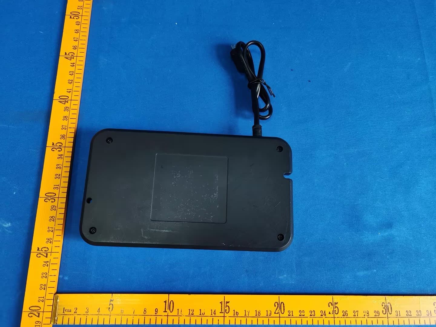
2AOTUKDDYM002B
Sep 22, 2024Control Box
Equipment Class
JAB - Part 15 Class B Digital Device2AOTUKDHM003D
Aug 11, 2024Handset
Equipment Class
DSC - Part 15 Security/Remote Control Transmitter
2AOTUKDDYM002A
Aug 08, 2024Control Box
Equipment Class
JAB - Part 15 Class B Digital Device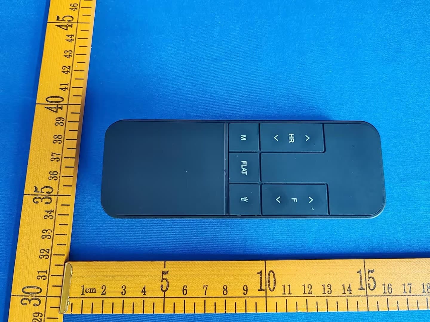
2AOTUKDHM003A
Jul 30, 2024Handset
Equipment Class
DXX - Part 15 Low Power Communication Device Transmitter