2AOTUKDH143Handset
Changzhou Kaidi Electrical Inc.
Click to zoom
Application Details
- Equipment Class
- DSC - Part 15 Security/Remote Control Transmitter
- Date of Grant
- Jun 09, 2020
- Application Purpose
- Original Equipment
- Date of Application
- Jun 09, 2020
- Equipment Note
- Handset
- Frequency Range
- 433.92000000 - 433.92000000
- Country
- China
Documents & Files
Document Text
Text extracted from the exhibit documents filed with the FCC. Open a document above to read the original.
Users Manual
1 / 5 User Manual 一、System connection diagram 二、Product List Name (Code) model Quantity Remarks control box KDDY036 1 Switching power supply KDDY01B 1 Optional Putter 2 KDYJT014‐025 1 Putter 1 KDYJT014‐026 1 Massage motor KDZYD028 1 Wireless hand controller KDH143(433M) 1 Light strip DY056 1 三、Performance parameter 1. Performance parameters of switching power supply: Input voltage AC100~240V 50/ 60Hz Rated output 29V DC / 2A Maximum output 29VDC/4A(Press 10% working system, up to 2 minutes of continuous operation, stop for 18 minutes) 2. Control box performance parameters Input voltage 29V DC Fader channel output 29VDC/4A(Press 10% working system, up to 2 minutes of continuous operation, stop for 18 minutes) Massage motor channel output 29V DC / 1A Lamp with channel output 12V DC / 1A FCC ID: 2AOTUKDH143 FCC ID: 2AOTUKDDY036 2 / 5 3. Wireless remote controller performance parameters Operating Voltage 4.5V Power supply 3 AAA batteries (KDH143) stand‐by current <10uA 4. Pusher performance par ameters: parameter name Putter 1 Putter 2 Voltage and current 29VDC/ 4A (According to the 10% working system, the maximum continuous work for 2 minutes and 18 minutes stop) No‐load speed 4‐6mm 4‐6mm Installation dimensions 300mm 330 mm stroke 60 mm 100 mm Maximum thrust 6000N 6000N 5. Massage motor performance parameters: Rated voltage 29V Two massage motors have the same parameters Rated current 300mA/ Pc 6. Light strip performance parameters: Rated voltage 12V Up to 2 light strips can be connected in series Rated current 20mA/ Pc 四、Precautions 1、Before use, please make sure to connect the cable correctly according to the system connection diagram, and then connect the main power supply; 2、Children, the elderly and people with disabilities, please use under supervision; 3、Do not plug or unplug any connecting wires when the power is turned on, it ma y cause malfunction of the oper ation function. If this happens, the main power supply can be cut off, and it can be restored after turning on again after about 30s 4、Before using for the first time, you should first pair the wireless hand controller with the control box. The specific me thods are as f ollows: a Press the pairing button on the control box and hold 3S, The indicator is flashing quickly, release the button; b Press any key on the hand control within 10s, the control box indicator stops flashing to indicate successful pairing, the control box indicator is alw ays on. If no key is pr essed within 10s, the control box indicator stops flashing, the original paired hand control Without being emptied, the control box indicator is always on; c After the pairing is successful, press the button and the corresponding function starts to execute; 5、The control box ca n be paired with two hand controllers, if paired with the third one, the first one will be cleared. 6、It is not recommended to operate multiple pushers at the same time, except for special functions; 7、Please replace the battery of the hand controller in time. When not using for a long time, the b atte ry should be taken out. 3 / 5 五、Key function description 1、Wireless hand control panel diagram 2、Key function table of hand controller (KDH143): Key symbol Key Function Remarks Press and hold the push rod 2 extended, stop when released Press and hold the push rod 2 to retract, release to stop Press and hold the push rod 1 extended, stop when released Press and hold the push rod 1 retracted, stop when released Press and release, push rod 1 and push rod 2 are fully retracted to stop, press any key to stop during operation Press and release, push rod 1 and push rod 2 run to the ZERO position preset by the system, and stop, press any key during the operation to stop Press and hold for 3s, the backlight of the relevant key in the fader control area flashes 3 times, and all the keys are locked; after long press 3S, the backlight of the relevant key in the fader control area flashes 3 times, and then unlock 4 / 5 Press the SET button, the backlight of the related buttons in the fader control area turns from off to steady on, you can press the memory position button 1 or 2, the memory button will memorize the current position of the fader 1 and the fader 2 Becomes steady light. If there is no key press in 3S, this SET is invalid and enters low power consumption) Use the memory button 1 or 2 to re-memorize the current position, then the last memory position of the button will be deleted; if the SET button has never been used before, the default is the top Press and release, push rod 1 and push rod 2 run to user set position 1 stop, press any key to stop during operation Press and release, push rod 1 and push rod 2 run to user set position 2 stop, press any key to stop during operation Press once to turn on the lamp under the bed, then press it again to turn of f; long press 2S to turn off the lamp Note: When any key is pressed, the backlight turns on. If there is no operation for 3S, the backlight turns off automatically and enters low power consumption If something goes wrong, please reload the battery FCC Statement Any Changes or modifications not expressly approved by the party responsible for compliance could void the user’s authority to operate the equipment. This device complies with part 15 of the FCC Rules. Operation is subject to the following two conditions: (1) This device may not cause harmful interference, and (2) This device must accept any interference received, including interference that may cause undeundesired operation. Note : This equipment has been tested and found to comply with the limits for a Class B digital device, pursuant to part 15 of the FCC Rules. These limits are designed to provide reasonable protection against harmful interference in a residential installation. This equipment generates,uses and can radiate radio frequency energy and, if not installed and used in accordance with the instructions, may cause harmful interference to radio communications. However, there is…
Text truncated - open the document above for the full version.
Cover Letter(s)
Company: Changzhou Kaidi Electrical Inc. Add: Jiangcun, Henglin Town, changzhou, China Tel: (86)519-67898510 Fax: (86)519-67898509 E-mail: [email protected] FCC Confidential Authorization Date: 2019-12-31 FEDERAL COMMUNICATIONS COMMISSIONS Authorization and Evaluation Division 7435 Oakland Mills Road Columbia, MD 21046 Subject: Confidentiality Request regarding application for certification of FCC ID: 2 AOTUKDH143 To: whom it may concern, In accordance with Sections 0.457 and 0.459 of the Commission’s Rules, Changzhou Kaidi Electrical Inc. hereby requests long-term confidential treatment of information accompanying this application as outlined below: Block Diagram Schematics Operation Description The above materials contain proprietary and confidential information not customarily released to the public. The public disclosure of these materials provides unjustified benefits to its competitors in the market. Sincerely Yours, Signature: Typed or Printed Name: Qin Yin Title: Engineer
External Photos
EXHIBIT A - EUT EXTERNAL PHOTOGRAPHS
Internal Photos
EXHIBIT B - EUT INTERNAL PHOTOGRAPHS Antenna
Test Report
Note: This test report is prepared for the customer shown above and for the device described herein. It may not be duplicated or used in part without prior written consent from Bay Area Compliance Laboratories Corp. This report is valid only with a valid digital signature. The digital signature may be available only under the Adobe software above version 7.0. FCC PART 15.231 TEST REPORT For Changzhou Kaidi Electrical Inc. Jiangcun, Henglin Town, Changzhou, China FCC ID: 2AOTUKDH143 Report Type: Original Report Product Type: Handset Test Engineer: Chao Gao Report Number: RSHA191231002-00A Report Date: 2020-05-27 Reviewed By: Oscar Ye EMC Manager Prepared By: Bay Area Compliance Laboratories Corp. (Kunshan) No.248 Chenghu Road, Kunshan, Jiangsu province, China Tel: +86-0512-86175000 Fax: +86-0512-88934268 www.baclcorp.com.cn Bay Area Compliance Laboratories Corp. (Kunshan) Report No.: RSHA191231002-00A FCC Part 15.231 Page 2 of 21 TABLE OF CONTENTS GENERAL INFORMATION ....................................................................................................................................... 3 PRODUCT DESCRIPTION FOR EQUIPMENT UNDER TEST (EUT) ..................................................................................... 3 OBJECTIVE ................................................................................................................................................................... 3 RELATED SUBMITTAL(S)/GRANT(S) ............................................................................................................................. 3 TEST METHODOLOGY .................................................................................................................................................. 3 MEASUREMENT UNCERTAINTY .................................................................................................................................... 4 TEST FACILITY ............................................................................................................................................................. 4 SYSTEM TEST CONFIGURATION .......................................................................................................................... 5 JUSTIFICATION ............................................................................................................................................................. 5 EUT EXERCISE SOFTWARE .......................................................................................................................................... 5 EQUIPMENT MODIFICATIONS ....................................................................................................................................... 5 SUPPORT EQUIPMENT LIST AND DETAILS .................................................................................................................... 5 EXTERNAL I/O CABLE .................................................................................................................................................. 5 BLOCK DIAGRAM OF TEST SETUP ................................................................................................................................ 6 SUMMARY OF TEST RESULTS ............................................................................................................................... 7 TEST EQUIPMENT LIST ........................................................................................................................................... 8 FCC§15.203 - ANTENNA REQUIREMENT .............................................................................................................. 9 APPLICABLE STANDARD .............................................................................................................................................. 9 ANTENNA CONNECTED CONSTRUCTION ...................................................................................................................... 9 FCC §15.205, §15.209, §15.231 (B) - RADIATED EMISSIONS ............................................................................. 10 APPLICABLE STANDARD ............................................................................................................................................ 10 EUT SETUP ................................................................................................................................................................ 11 EMI TEST RECEIVER SETUP ....................................................................................................................................... 12 TEST PROCEDURE ...................................................................................................................................................... 12 CORRECTED AMPLITUDE & MARGIN CALCULATION ................................................................................................. 12 TEST RESULTS SUMMARY .......................................................................................................................................... 12 TEST DATA ................................................................................................................................................................ 12 FCC §15.231(A) (1) - DEACTIVATION TESTING ................................................................................................. 18 APPLICABLE STANDARD ............................................................................................................................................ 18 TEST PROCEDURE ...................................................................................................................................................... 18 TEST DATA ................................................................................................................................................................ 18 FCC §15.231(C) - 20DB EMISSION BANDWIDTH TESTING ...............…
Text truncated - open the document above for the full version.
Test Setup Photos
EXHIBIT C - TEST SETUP PHOTOGRAPHS Radiated Emissions (Below 1GHz) Radiated Emissions (Above 1GHz)
Contact Information
Applicant
Qin Yin
Test Firm
Bay Area Compliance Laboratories Corp. (Kunshan)Mr. John Chan
[email protected]+86 0512 86175000
Technical Specifications
| # | Rule Parts | Frequency Range | Power Output |
|---|---|---|---|
| 1 | 15.231 | 433.92 MHz - 433.92 MHz | - |
Other Applications from Changzhou Kaidi Electrical Inc.

2AOTUKDDY109C
Sep 26, 2024Control Box
Equipment Class
JAB - Part 15 Class B Digital Device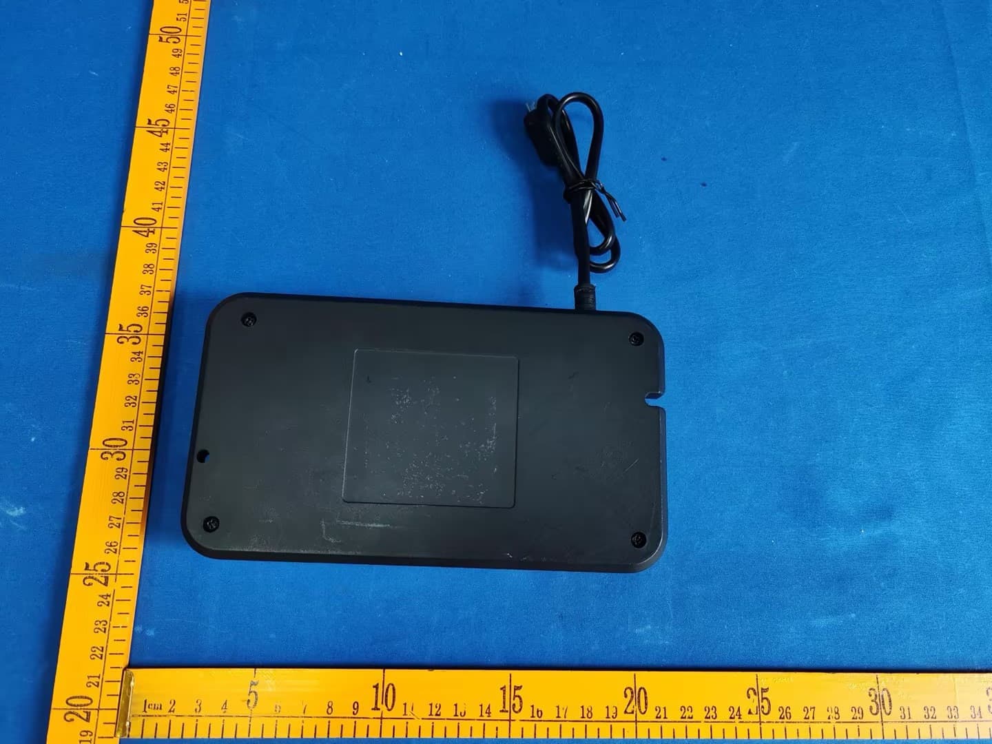
2AOTUKDDYM002B
Sep 22, 2024Control Box
Equipment Class
JAB - Part 15 Class B Digital Device2AOTUKDHM003D
Aug 11, 2024Handset
Equipment Class
DSC - Part 15 Security/Remote Control Transmitter
2AOTUKDDYM002A
Aug 08, 2024Control Box
Equipment Class
JAB - Part 15 Class B Digital Device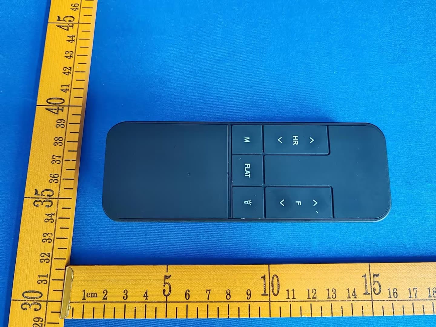
2AOTUKDHM003A
Jul 30, 2024Handset
Equipment Class
DXX - Part 15 Low Power Communication Device Transmitter