2AOUZ18100931Instrument cluster with Immobilizer 18100931
Continental Automotive Technologies GmbH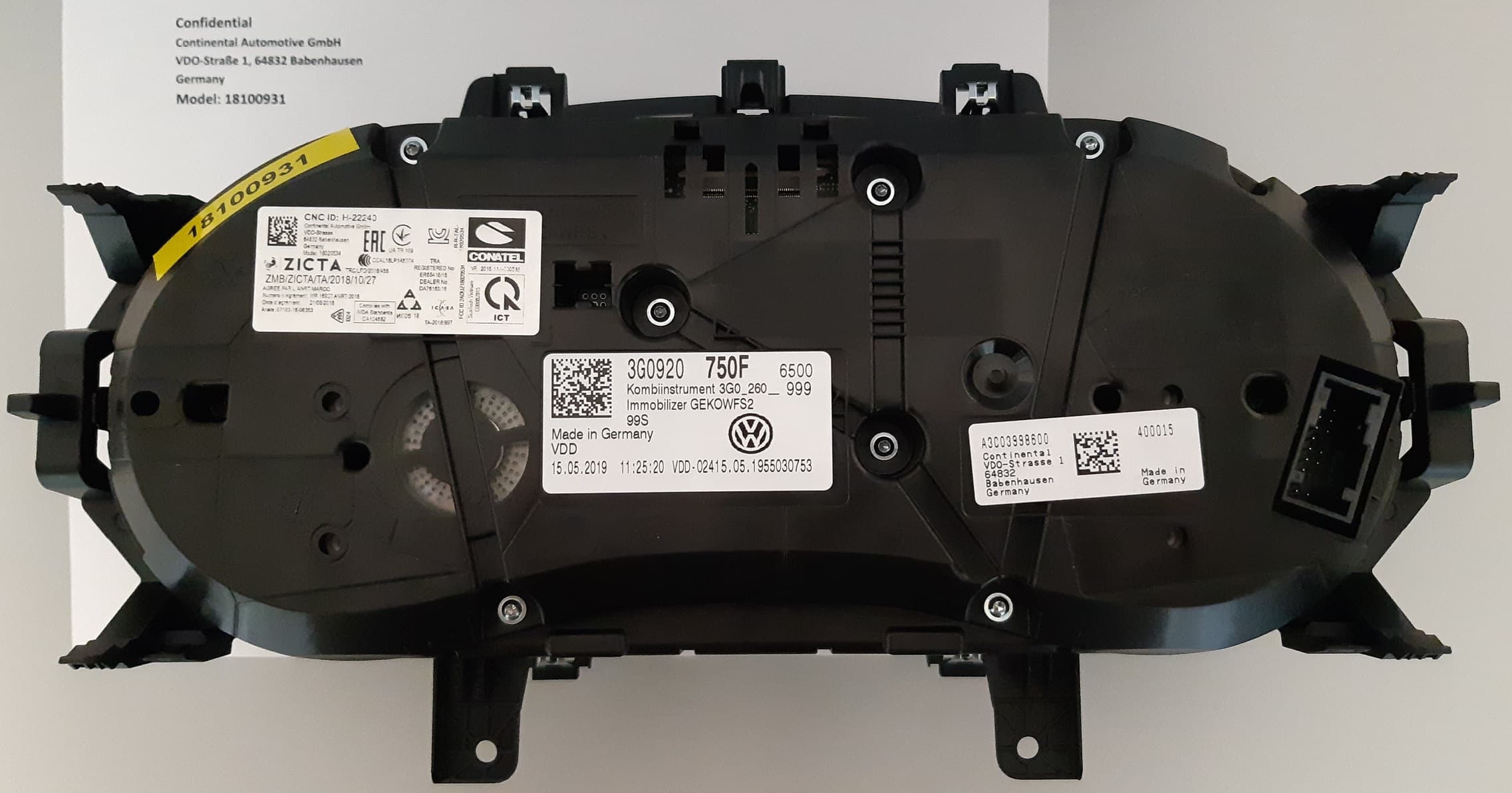
Click to zoom
Application Details
- Equipment Class
- DXX - Part 15 Low Power Communication Device Transmitter
- Date of Grant
- Jan 19, 2020
- Application Purpose
- Original Equipment
- Date of Application
- Jan 19, 2020
- Equipment Note
- Instrument cluster with Immobilizer 18100931
- Frequency Range
- 0.12500000 - 0.12500000
- Country
- Germany
Documents & Files
Document Text
Text extracted from the exhibit documents filed with the FCC. Open a document above to read the original.
Users Manual
NOTICE If the vehicle has been driven at high load for a long period, the engine can overheat when it is switched off. In order to avoid damage to the en- gine, allow the engine to run in neutral for ap- proximately two minutes before switching it off. After the engine is switched off, the radia- tor fan in the engine compartment may run on for some minutes, even if the ignition is switched off or the vehicle key has been re- moved. The radiator fan will switch itself off au- tomatically. Electronic immobiliser The immobiliser helps to prevent the engine from being started and driven with an unauthor- ised vehicle key. There is a chip in the key. It deactivates the im- mobiliser automatically when a valid vehicle is located inside the vehicle → page 79. The electronic immobiliser is activated automati- cally once the valid vehicle key is no longer loca- ted inside the vehicle → page 79. The engine can only be started using a genuine Volkswagen vehicle key with the correct code. Coded vehicle keys are available from a Volkswa- gen dealership → page 77. The vehicle cannot be operated properly if you do not have a genuine Volkswagen key. Troubleshooting Fig. 132 On the right-hand side of the steering col- umn: emergency start function in vehicles with the keyless access locking and starting system. Engine management system fault The indicator lamp lights up yellow. Engine management system fault. –The engine should be checked by a qualified workshop as soon as possible. Engine speed limited The indicator lamp lights up yellow. The engine speed has been limited to prevent the engine from overheating. The engine speed is shown on the instrument cluster display. The engine speed limit is removed in the follow- ing instances: –The engine is no longer at a critical tempera- ture. –Driver's foot has been taken off the accelera- tor. in conjunction with engine speed limit due to a fault in the engine management system The indicator lamps light up yellow. The engine speed limit is triggered by a fault in the engine management system. –Make sure that the displayed engine speed is not exceeded. –The engine should be checked by a qualified workshop as soon as possible. Driving 147 3G0012720AF 18100931 Preheating system / engine management system Vehicles with diesel engine: The indicator lamp lights up yellow. The indicator lamp in the instrument cluster lights up for a few seconds when the diesel en- gine is being pre-heated. The indicator lamp flashes yellow. There is a fault in the engine management sys- tem. –The engine should be checked by a qualified workshop as soon as possible. No valid vehicle key detected A corresponding display will appear in the instru- ment cluster. The vehicle key may not be detected if the but- ton cell in the key is discharged or too weak. It is necessary to perform an emergency start: –Depress and hold the brake pedal. –Hold the vehicle key to the right of the steer- ing column trim directly after pressing the starter button → Fig. 132. –The ignition is switched on automatically, and in some cases the engine is started. Engine cannot be switched off The engine cannot be switched off by pressing the starter button briefly. It is necessary to perform an emergency switch- off: –Press the starter button twice within a few seconds or press and hold once. The engine will switch off automatically → in Starter button on page 145. Engine cannot be started A corresponding message appears on the instru- ment cluster display if an unauthorised vehicle key is used, or in the event of a system fault. –Use an authorised vehicle key. –Seek expert assistance if the problem persists. Start/stop system Fig. 133 In the lower part of the centre console: button for the start/stop system. The start/stop system automatically switches the engine off when the vehicle is coming to a stop and when stationary. When required, the engine restarts automatically. Switching on the start/stop system The function is automatically activated every time the ignition is switched on. The instrument cluster display will show information about the current status. Vehicles with a DSG ® dual clutch gearbox may be fitted with a start/stop system featuring eco- coasting. Eco-coasting is deactivated and activa- ted in conjunction with the start/stop system. Additional information about the start/stop mode is available by pressing the button or function button and the Vehicle , Selection , and Vehicle status function buttons in the Infotain- ment system. This information also applies to coasting. Always switch off the start/stop system manually when driving through water. Indicator lamps If the indicator lamp lights up, the start/stop system is available and the automatic engine stop is active. If the indicator lamp lights up, the start/stop system is not available, or the start/stop system has started the engine automatically → page 149. The display on the instrument cluster may show the status of the start/stop system. Owner's manual 148
ID Label/Location Info
XXXX-XX-X-XXXX NR: IFT: XXXXXXX18-XXXX Anatel: HHHH-AA-FFFF 12345/SDPPI/2011 1234 R-CRM-ABC- XXXXXXXXXXX MR XXXXX ANRT YEARDD/MM/YYYY AGREE PAR L ́ANRT MAROC Numéro d ́agrément:Date d ́agrément: CNC ID: XX-9999 ZZZZZ/ZZ A REGISTERED No: ERZZZZZ/ZZ DEALER No: DA TRC/LPD/YEAR/666 TAC NO.: xxxx/yyyy Approved by PTA Hi M eччина XXXXZZXXZZZZXZ TR И011 YY 024 Complies with IMDA Standards APPROVED SunTech VN C00082015 TA-YEAR/XXXX DA10 5282 Continental Automotive GmbHVDO-Strasse 164832 BabenhausenGermanyModel: 18100931 IC: 23650- 18100931 FCC ID 2AOUZ 18100931
Test Report
Page 1 of 6 The test results relate only to the individual items which have been tested. This report shall not be reproduced in parts without the written approval of the testing laboratory © Copyright: All rights reserved by CETECOM Annex 1: Measuring diagrams to T E S T R E P O R T No.: 19-1-0009001T09a According to: FCC Regulations Title 47, §15.209, Subpart C ISED-Regulations RSS-Gen, Issue 5 for Continental Automotive GmbH Instrument cluster with Immobilizer 18100931 FCC-ID: 2AOUZ18100931 ISED ID: 23650-18100931 Laboratory Accreditation and Listings Accredited EMC-Test Laboratory accredited according to DIN EN ISO/IEC 17025 CETECOM GmbH Laboratory Radio Communications & Electromagnetic Compatibility Im Teelbruch 116 • 45219 Essen • Germany Registered in Essen, Germany, Reg. No.: HRB Essen 8984 Tel.: + 49 (0) 20 54 / 95 19-954 • Fax: + 49 (0) 20 54 / 95 19-964 E-mail: [email protected] • Internet: www.cetecom.com Annex 1 to Test Report 19-1-0009001T09a, Page 2 of 6 CETECOM_TR19_1_0009001T09a_A1 Table of contents 1. MEASURING DIAGRAMS ............................................................................................................................. 3 1.1. Occupied bandwidth (ISED) ......................................................................................................................... 3 1.2. Radiated emission - carrier strength on 125 kHz .......................................................................................... 4 1.3. Radiated emission – 9 kHz to 30 MHz ......................................................................................................... 5 1.4. Radiated emission – 30 MHz to 1 GHz ........................................................................................................ 6 Annex 1 to Test Report 19-1-0009001T09a, Page 3 of 6 CETECOM_TR19_1_0009001T09a_A1 1. Measuring diagrams 1.1. Occupied bandwidth (ISED) Diagram 1: OBW 99% function activated Annex 1 to Test Report 19-1-0009001T09a, Page 4 of 6 CETECOM_TR19_1_0009001T09a_A1 1.2. Radiated emission - carrier strength on 125 kHz Diagram 2.01_H_Field_TX_EUT_standing Diagram 2.02_H_Field_TX_EUT_lying -50 -40 -30 -20 -10 0 10 20 30 99,96 105 110 115 120 125 130 135 140 145 150 Evaluation Result in dBμV/m Frequ en cy in kHz 125,000 kHz -3,089 dBμV/m FCC15.209_Magnetic_Field -50 -40 -30 -20 -10 0 10 20 30 99,96 105 110 115 120 125 130 135 140 145 150 Evaluation Result in dBμV/m Frequ en cy in kHz FCC15.209_Magnetic_Field 125,080 kHz -12,499 dBμV/m Annex 1 to Test Report 19-1-0009001T09a, Page 5 of 6 CETECOM_TR19_1_0009001T09a_A1 1.3. Radiated emission – 9 kHz to 30 MHz Diagram 2.05_RSE_TX_EUT_standing (worst case position) -60 -50 -40 -30 -20 -10 0 10 20 30 40 50 9k203050100k2003005001M2M3M5M10M2030M Evaluation Result in dBμV/m Frequ en cy in H z FCC15.209_Magnetic_Field 124,920 kHz -7,688 dBμV/m 21,942000 MH z 19,267 dBμV/m 430,000 kHz -30,046 dBμV/m 17,400 kH z -13,582 dBμV/m Annex 1 to Test Report 19-1-0009001T09a, Page 6 of 6 CETECOM_TR19_1_0009001T09a_A1 1.4. Radiated emission – 30 MHz to 1 GHz Diagram 3.01_RSE_TX_EUT_standing Diagram 3.02_RSE_TX_EUT_lying End of Annex 1 Level in dBμV/m Level in dBμV/m
Test Report
Page 1 of 23 The test results relate only to the individual items which have been tested. This report shall not be reproduced in parts without the written approval of the testing laboratory © Copyright: All rights reserved by CETECOM T E S T R E P O R T No.: 19-1-0009001T09a According to: FCC Regulations Title 47, §15.209 ISED-Regulations RSS-Gen, Issue 5 for Continental Automotive GmbH Instrument cluster with Immobilizer 18100931 FCC-ID: 2AOUZ18100931 ISED ID: 23650-18100931 Laboratory Accreditation and Listings Accredited EMC-Test Laboratory accredited according to DIN EN ISO/IEC 17025 CETECOM GmbH Laboratory Radio Communications & Electromagnetic Compatibility Im Teelbruch 116 • 45219 Essen • Germany Registered in Essen, Germany, Reg. No.: HRB Essen 8984 Tel.: + 49 (0) 20 54 / 95 19-954 • Fax: + 49 (0) 20 54 / 95 19-964 E-mail: [email protected] • Internet: www.cetecom.com Test Report 19-1-0009001T09a, Page 2 of 23 CETECOM_TR19_1_0009001T09a Table of contents 1. SUMMARY OF TEST RESULTS................................................................................................................... 3 1.1. TEST OVERVIEW ACCORDING FCC PART 15C AND CANADIAN RSS-STANDARDS .................. 3 1.2. ATTESTATION: .......................................................................................................................................... 4 2. ADMINISTRATIVE DATA ............................................................................................................................ 5 2.1. Identification of the testing laboratory .......................................................................................................... 5 2.2. Test location ................................................................................................................................................. 5 2.3. Organizational items ..................................................................................................................................... 5 2.4. Applicant’s details ........................................................................................................................................ 5 2.5. Manufacturers’ details .................................................................................................................................. 5 3. EQUIPMENT UNDER TEST (EUT) .............................................................................................................. 6 3.1. Technical data of main EUT declared by applicant ...................................................................................... 6 3.2. EUT: Type, S/N etc. and short descriptions used in this test report ............................................................. 6 3.3. Auxiliary Equipment (AE): Type, S/N etc. and short descriptions ............................................................... 6 3.4. EUT set-ups .................................................................................................................................................. 7 3.5. EUT operating modes ................................................................................................................................... 7 3.6. Configuration of cables used for testing ....................................................................................................... 7 4. DESCRIPTION OF TEST SYSTEM SET-UP’S ........................................................................................... 8 4.1. Test system set-up for radiated magnetic field measurements below 30 MHz ............................................. 8 4.2. Test system set-up for radiated electric field measurement 30 MHz to 1 GHz ............................................ 9 5. MEASUREMENTS ........................................................................................................................................ 10 5.1. RF-Parameter - 99% occupied Bandwith ................................................................................................... 10 5.2. General Limit - Radiated field strength emissions below 30 MHz ............................................................. 12 5.3. General Limit - Radiated field strength emissions, 30 MHz - 1 GHz ......................................................... 14 5.4. Measurement uncertainties ......................................................................................................................... 17 6. ABBREVIATIONS USED IN THIS REPORT ............................................................................................ 18 7. ACCREDITATION DETAILS OF CETECOM’S LABORATORIES AND TEST SITES .................... 18 8. INSTRUMENTS AND ANCILLARY ........................................................................................................... 19 8.1. Used equiment “CTC” ................................................................................................................................ 19 9. VERSIONS OF TEST REPORTS (CHANGE HISTORY) ........................................................................ 23 Table of annex Total pages ANNEX 1: MEASURING DIAGRAMS (CETECOM_TR19_1_0009001T09A_A1) 6 ANNEX 2: EXTERNAL PHOTOGRAPHS (CETECOM_TR19_1_0009001T09A_A2) 6 ANNEX 3: TEST SETUP PHOTOGRAPHS (CETECOM_TR19_1_0009001T09A_A3) 4 ANNEX 4: INTERNAL PHOTOGRAPHS (TO BE PROVIDED BY APPLICANT) - The listed attachments are an integral part of this report. Test Report 19-1-0009001T09a, Page 3 of 23 CETECOM_TR19_1_0009001T09a 1. Summary of test results The test results apply exclusively to the test samples as presented in this Report. The CETECOM GmbH does not assume responsibility for any conclusions and generalizations taken in conjunction with other specimens or samples of the type of the item presented to tests. Also we refer on special conditions which the applicant should fulfill according §2.927 to §2.948, special focus regarding modification of the equipment and availability of sample e…
Text truncated - open the document above for the full version.
Test Setup Photos
Page 1 of 4 The test results relate only to the individual items which have been tested. This report shall not be reproduced in parts without the written approval of the testing laboratory © Copyright: All rights reserved by CETECOM Annex 3: Test setup photographs to T E S T R E P O R T No.: 19-1-0009001T09a According to: FCC Regulations Title 47, §15.209 ISED-Regulations RSS-Gen, Issue 5 RSS-210, Issue 9 for Continental Automotive GmbH 18100931 Instrument cluster with Immobilizer FCC-ID: 2AOUZ18100931 ISED: 23650-18100931 Laboratory Accreditation and Listings Accredited EMC-Test Laboratory accredited according to DIN EN ISO/IEC 17025 CETECOM GmbH Laboratory Radio Communications & Electromagnetic Compatibility Im Teelbruch 116 • 45219 Essen • Germany Registered in Essen, Germany, Reg. No.: HRB Essen 8984 Tel.: + 49 (0) 20 54 / 95 19-954 • Fax: + 49 (0) 20 54 / 95 19-964 E-mail: [email protected] • Internet: www.cetecom.com Annex 3 to Test Report 19-1-0009001T09a, Page 2 of 4 CETECOM_TR19_1_0009001T09a_A3 Table of contents 1. TEST SETUP PHOTOGRAPHS ..................................................................................................................... 3 1.1. Measurement for radiated emission – 9 kHz to 30 MHz (including carrier strength) .................................. 3 1.2. Measurement for radiated emission – 30 MHz to 1 GHz ............................................................................. 4 Annex 3 to Test Report 19-1-0009001T09a, Page 3 of 4 CETECOM_TR19_1_0009001T09a_A3 1. Test setup photographs 1.1. Measurement for radiated emission – 9 kHz to 30 MHz (including carrier strength) Photograph 1: Overall view of the test setup in the semi-anechoic chamber. EUT stands. Photograph 2: Close view of the test setup in the semi-anechoic chamber. EUT lies. Annex 3 to Test Report 19-1-0009001T09a, Page 4 of 4 CETECOM_TR19_1_0009001T09a_A3 1.2. Measurement for radiated emission – 30 MHz to 1 GHz Photograph 3: Overall view of the test setup in the semi-anechoic chamber. EUT stands. Photograph 4: Close view of the test setup in the semi-anechoic chamber. EUT stands.
Contact Information
Applicant
Bettina Christ(Team Lead RF Homologation)
Test Firm
cetecom advanced GmbHGerald Schmidt
Technical Specifications
| # | Rule Parts | Frequency Range | Power Output |
|---|---|---|---|
| 1 | 15C | 0.125 MHz - 0.125 MHz | - |
Other Applications from Continental Automotive Technologies GmbH
2AOUZ-23040401
Sep 24, 2023VW instrument cluster
Equipment Class
DCD - Part 15 Low Power Transmitter Below 1705 kHz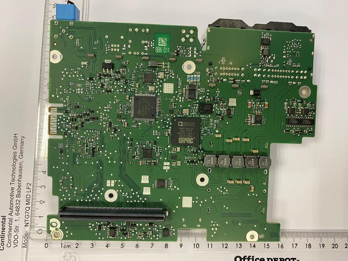
2AOUZNTG7QMIDLF2
Jan 22, 2023Automotive head unit to be installed in cars with the following features FM, AM, DAB, USB, Bluetooth, WLAN and GNSS
Equipment Class
DTS - Digital Transmission System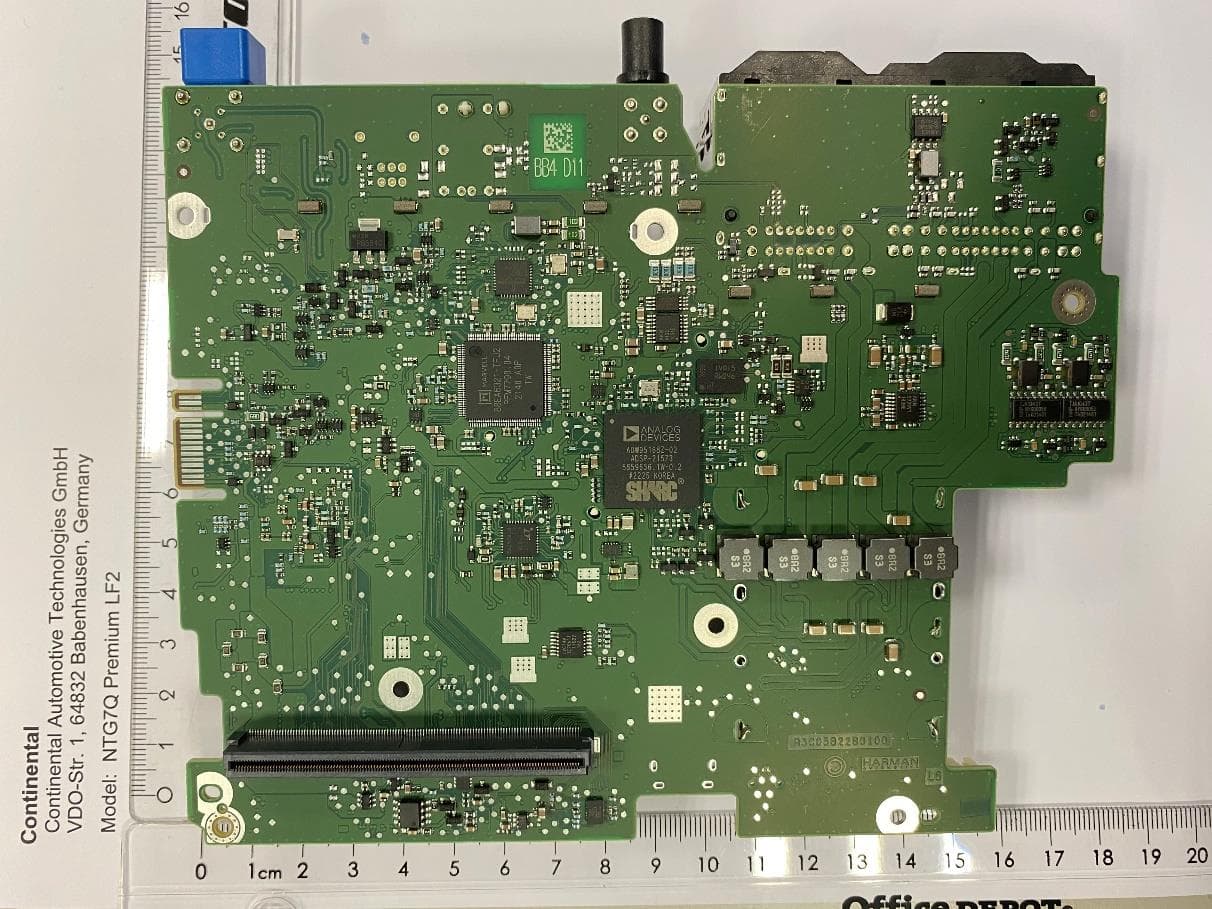
2AOUZNTG7QPRELF2
Jan 22, 2023Automotive head unit to be installed in cars with the following features FM, AM, DAB, USB, Bluetooth, WLAN and GNSS
Equipment Class
DSS - Part 15 Spread Spectrum Transmitter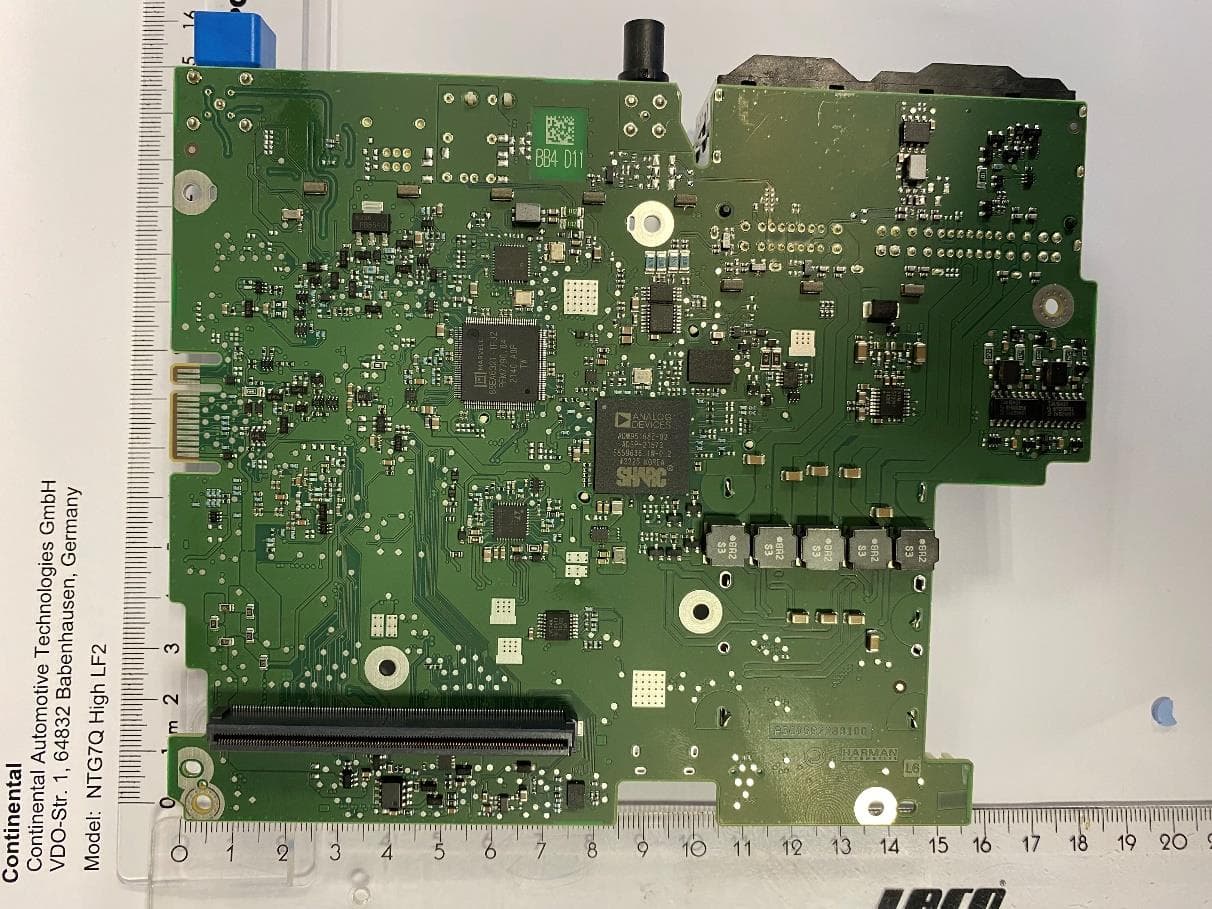
2AOUZNTG7QHIGLF2
Jan 19, 2023Automotive head unit to be installed in cars with the following features FM, AM, DAB, USB, Bluetooth, WLAN and GNSS
Equipment Class
DSS - Part 15 Spread Spectrum Transmitter
2AOUZNTG7PRELFT2
Oct 01, 2020Automotive head unit to be installed in cars with the following features FM AM DAB USB Bluetooth WLAN and GNSS
Equipment Class
DSS - Part 15 Spread Spectrum Transmitter