2AOW6HPBT010Wireless Headphones
Shantou Xinyu Industry Co., Ltd.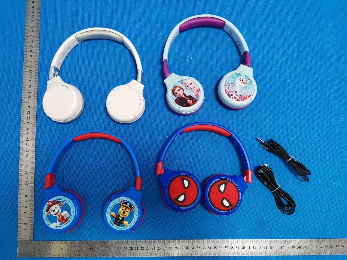
Click to zoom
Application Details
- Equipment Class
- DSS - Part 15 Spread Spectrum Transmitter
- Date of Grant
- Oct 12, 2020
- Application Purpose
- Original Equipment
- Date of Application
- Oct 12, 2020
- Equipment Note
- Wireless Headphones
- Frequency Range
- 2402.00000000 - 2480.00000000
- Country
- China
Documents & Files
Document Text
Text extracted from the exhibit documents filed with the FCC. Open a document above to read the original.
Users Manual
BLUETOOTH ® & WIRED HEADPHONES CASQUE BLUETOOTH ® & FILAIRE MODE D’EMPLOI INSTRUCTION MANUAL MANUAL DE INSTRUCCIONES MANUAL DE INSTRUÇÕES MANUALE DI ISTRUZIONI BEDIENUNGSANLEITUNG GEBRUIKSAANWIJZING BRUKSANVISNING INSTRUKTIONSMANUAL KÄYTTÖOPAS BRUKSANVISNING BRUKSANVISNINGEN HPBT010series Booklet Size: 80(W) x 157(H)mm HPBT010series_Acoustix_IM2360_V01.indb 11/9/2020 10:42 AM 2 5 4 3 1 HPBT010series_Acoustix_IM2360_V01.indb 21/9/2020 10:42 AM 33 FRANÇAIS Lors du déballage, assurez-vous que les pièces suivantes soient incluses : 1 x Casque Bluetooth® 2 en 1 / 1 x Câble de charge USB type-C / 1 x Câble de connexion Aux In 3,5 mm / 1 x Mode d’emploi AVERTISSEMENT: Tous les matériaux d’emballage, comme le scotch, les feuilles en plastique, les ficelles et les étiquettes ne font pas partie de ce produit et doivent être jetés. DÉBALLAGE DE L’APPAREIL Reportez-vous au schéma p.2. 1. Marche / Arrêt et Activer / désactiver Bluetooth® 2. Entrée Aux In Le casque Bluetooth® fonctionne avec un câble de charge USB type-C (inclus) ou un adaptateur d’alimentation USB 5V 1A. Alimentation 1. Assurez-vous de désactiver le Bluetooth® avant de recharger le casque. 2. Insérez la petite extrémité du câble USB type-C (inclus) dans le port de charge USB type-C. 3. Raccordez l’autre extrémité du câble au port USB de votre ordinateur en marche ou à un adaptateur d’alimentation USB branché à une prise murale. 4. L’indicateur LED s’allume en rouge quand le casque se recharge, puis s’éteint une fois la recharge terminée. Remarque : Vous pouvez continuer à écouter de la musique en connexion auxiliaire pendant le chargement de l’appareil. AVERTISSEMENT : D’importantes interférences électromagnétiques ou des décharges électrostatiques peuvent provoquer un dysfonctionnement ou une perte de données. Si l’appareil ne fonctionne pas correctement, éteignez-le puis rallumez-le ou débranchez le câble USB. AVERTISSEMENT : • Risque d’explosion si la batterie est mal remplacée. Veillez à ne la remplacer qu’avec une même ou batterie équivalente (Instructions réservées au Service de réparation, les piles ne doivent pas être remplacées par un utilisateur). • La batterie ne doit pas être exposée à de fortes chaleurs, telles que la lumière du soleil, le feu ou toute autre chose de semblable. • Garder une distance minimale autour de l’appareil pour une aération suffisante. • Il convient de ne pas obstruer les ouvertures d’aération par des objets tels que journaux, nappes, rideaux, etc. • Il convient de ne pas placer sur l’appareil des sources de flammes nues, telles que des bougies allumées. • L’appareil est destiné à être utilisé sous un climat tempéré et/ou tropical. • Les piles doivent être jetées de façon conforme. Les déposer dans des bacs de collecte prévus afin de protéger l’environnement. EMPLACEMENT DES TOUCHES CHARGEMENT DE L’APPAREIL 3. Lecture / pause 4. Suivant / volume + 5. Précédent / volume - HPBT010series_Acoustix_IM2360_V01.indb 31/9/2020 10:42 AM 45 FRANÇAIS Le casque fonctionne sans-fil en Bluetooth® ou en mode filaire avec le câble AUX-IN (inclus). - Pour allumer/éteindre le casque, appuyez quelques secondes sur le bouton ON/OFF (1). - En mode filaire, connectez le câble AUX-IN à l’entrée AUX-IN (2). Les boutons Précédent/volume – (5), Lecture/Pause (3) et Suivant/volume + (4) sont désactivés. Utilisez les commandes de votre lecteur audio pour contrôler la lecture. - En mode Bluetooth® : • Appuyez sur Lecture/pause (3) pour lire ou mettre en pause la piste audio. • Appuyez brièvement sur les boutons Précédent et Suivant (4, 5) pour changer de piste audio. • Appuyez longuement sur les boutons Précédent et Suivant (4, 5) pour changer le volume. • Le casque est équipé d’un microphone que vous pouvez utiliser pour répondre à vos appels. Pour répondre à votre appel et raccrocher, appuyez sur le bouton Play/Pause (3). - Pour changer de mode, débranchez le câble AUX-IN ou désactiver le Bluetooth sur votre appareil mobile. Remarque : En mode aux-in, les boutons de contrôle de musique du casque sont désactivés. Veuillez utiliser les boutons de contrôle de votre lecteur. UTILISATION 1. Appuyez longuement sur le bouton Bluetooth (1) sur le casque. Le voyant LED clignote pour informer que l’appareil est prêt à être pairé. 2. Activez la fonction Bluetooth® de votre lecteur audio (smartphone, lecteur MP3, etc.) et assurez-vous d’être visible. 3. Sélectionnez le nom du casque audio (HPBT010) dans la liste des appareils Bluetooth pour vous connecter au casque. 4. Pour arrêter l’appairage avec le casque, désactivez le Bluetooth sur votre lecteur. Remarques : •Une fois allumée, l’enceinte recherche automatiquement un appareil qu’elle a auparavant synchronisé. •Si votre appareil avec fonction Bluetooth® a besoin d’un mot de passe, le code par défaut est : 0000. La marque et les logos Bluetooth® sont des marques déposées appartenant à Bluetooth SIG, Inc. et Lexibook® les utilise sous licence. Les autres marques de commerce et noms commerciaux appartiennent aux sociétés qui en sont respectivement détentrices. © 2020 Bluetooth SIG, Inc. FONCTION SANS FIL (BLUETOOTH®) • Technologie du Bluetooth ® 5.0 • Fréquence Bluetooth® : 2402 - 2480 MHz • Puissance de transmission : 5.4dBm • Batterie rechargeable intégrée, 250mAh/3.7V, Li-ion polymère • Avec prise audio de 3,5mm • Courant de charge : CC 5V, 1000mA • Durée de charge : environ 2 heures • Durée de lecture : jusqu’à 4-6 heures • Distance effective : 10m (ligne droite sans obstacle) SPÉCIFICATIONS TECHNIQUES HPBT010series_Acoustix_IM2360_V01.indb 41/9/2020 10:42 AM 45 FRANÇAIS Lexibook® S.A. 6 avenue des Andes Bâtiment 11 91940 Les Ulis – France Désignation : Casque stéréo Bluetooth® Référence / type : HPBT010series Le soussigné, Lexibook Limited, déclare que l’équipement radioélectrique du type HPBT010 series est conforme à la directive 2014/53/UE. Le texte complet de la déclaration UE de conformité est disponible à l’adresse internet suivante: http://www.lexibook.com/doc/hpbt010/hpbt010…
Text truncated - open the document above for the full version.
Cover Letter(s)
Shantou Xinyu Industry Co., Ltd. Agent Authorization Company: Shantou Xinyu Industry Co., Ltd. Address: Heping Zhongzhai Industial Zone Chaoyang District Product Name: Wireless Headphones Model Number(s): HPBT010 Product Description: Wireless Headphones We authorize MiCOM Labs Inc., 575 Boulder Court, Pleasanton, California 94566, USA, to act on our behalf on all matters concerning the certification of above named equipment. We declare that MiCOM Labs Inc. is allowed to forward all information related to the approval and certification of equipment to the regulatory agencies as required and to discuss any issues concerning the approval application. Any and all acts carried out by MiCOM Labs on our behalf shall have the same effect as acts of our own. Signature: Date: 2020-10-12 Name: James Fan Company: Shantou Xinyu Industry Co., Ltd.
External Photos
External Photos WHOLE VIEW OF EUT TOP VIEW OF EUT BOTTOM VIEW OF EUT FRONT VIEW OF EUT BACK VIEW OF EUT LEFT VIEW OF EUT RIGHT VIEW OF EUT VIEW OF EUT(PORT)-1 VIEW OF EUT(PORT)-2
ID Label/Location Info
FCC ID Label Location FCC ID: 2AOW6HPBT010
Internal Photos
Internal Photos OPEN VIEW OF EUT VIEW OF BATTERY 1 VIEW OF BATTERY 2 INTERNAL VIEW OF EUT-1 BT Antenna INTERNAL VIEW OF EUT-2 INTERNAL VIEW OF EUT-3
RF Exposure Info
RF EXPOSURE EVALUATION 1. PRODUCT INFORMATION Product Description Wireless Headphones Model Name HPBT010 FCC ID 2AOW6HPBT010 2. EVALUATION METHOD According to 447498 D01 General RF Exposure Guidance v05 The 1-g and 10-g SAR test exclusion thresholds for 100 MHz to 6 GHz at test separation distances ≤ 50 mm are determined by: [(max. power of channel, including tune-up tolerance, mW)/(min. test separation distance, mm)] ·[√f(GHz)] ≤ 3.0 for 1-g SAR and ≤ 7.5 for 10-g extremity SAR. Where f(GHz) is the RF channel transmit frequency in GHz Power and distance are rounded to the nearest mW and mm before calculation 3. CALCULATION BR/EDR: P t = 0.089dBm=1.02mW The value of the Maximum output power P t is referred to the test report of the CFR47 §15.247. The result for RF exposure evaluation SAR=(1.02mW /5mm) .[√2.402GHz)]=0.32<3.0 for 1-g SAR and ≤ 7.5 for 10-g extremity SAR. 4. CONCLUSION The SAR evaluation is not required.
Test Report
Page 1 of 72 FCC Test Report Report No.: AGC01278200910FE03 FCC ID : 2AOW6HPBT010 APPLICATION PURPOSE : Original Equipment PRODUCT DESIGNATION : Wireless Headphones BRAND NAME : N/A MODEL NAME : HPBT010 APPLICANT : Shantou Xinyu Industry Co., Ltd. DATE OF ISSUE : Sep. 29,2020 STANDARD(S) : FCC Part 15.247 REPORT VERSION : V1.0 Attestation of Global Compliance (Shenzhen) Co., Ltd Report No.: AGC01278200910FE03 Page 2 of 72 REPORT REVISE RECORD Report Version Revise Time Issued Date Valid Version Notes V1.0 / Sep. 29,2020 Valid Initial Release Report No.: AGC01278200910FE03 Page 3 of 72 TABLE OF CONTENTS 1. VERIFICATION OF CONFORMITY ............................................................................................................... 5 2. GENERAL INFORMATION ............................................................................................................................ 6 2.1. PRODUCT DESCRIPTION ..................................................................................................................... 6 2.2. TABLE OF CARRIER FREQUENCYS ..................................................................................................... 6 2.3. RECEIVER INPUT BANDWIDTH ............................................................................................................ 7 2.4. EXAMPLE OF A HOPPING SEQUENCY IN DATA MODE ....................................................................... 7 2.5. EQUALLY AVERAGE USE OF FREQUENCIES AND BEHAVIOUR ........................................................ 7 2.6. RELATED SUBMITTAL(S) / GRANT (S) .................................................................................................. 8 2.7. TEST METHODOLOGY .......................................................................................................................... 8 2.8. SPECIAL ACCESSORIES ....................................................................................................................... 8 2.9. EQUIPMENT MODIFICATIONS .............................................................................................................. 8 2.10. ANTENNA REQUIREMENT .................................................................................................................. 8 3. MEASUREMENT UNCERTAINTY ................................................................................................................. 9 4. DESCRIPTION OF TEST MODES ............................................................................................................... 10 5. SYSTEM TEST CONFIGURATION ............................................................................................................. 11 5.1. CONFIGURATION OF EUT SYSTEM .................................................................................................... 11 5.2. EQUIPMENT USED IN TESTED SYSTEM ............................................................................................. 11 5.3. SUMMARY OF TEST RESULTS ............................................................................................................. 11 6. TEST FACILITY ........................................................................................................................................... 12 7. PEAK OUTPUT POWER ............................................................................................................................. 13 7.1. MEASUREMENT PROCEDURE ........................................................................................................... 13 7.2. TEST SET-UP (BLOCK DIAGRAM OF CONFIGURATION) ................................................................... 13 7.3. LIMITS AND MEASUREMENT RESULT ............................................................................................... 14 8. 20DB BANDWIDTH ..................................................................................................................................... 20 8.1. MEASUREMENT PROCEDURE ........................................................................................................... 20 8.2. TEST SET-UP (BLOCK DIAGRAM OF CONFIGURATION) ................................................................... 20 8.3. LIMITS AND MEASUREMENT RESULTS ............................................................................................. 21 9. CONDUCTED SPURIOUS EMISSION ........................................................................................................ 27 9.1. MEASUREMENT PROCEDURE ........................................................................................................... 27 Report No.: AGC01278200910FE03 Page 4 of 72 9.2. TEST SET-UP (BLOCK DIAGRAM OF CONFIGURATION) ................................................................... 27 9.3. MEASUREMENT EQUIPMENT USED .................................................................................................. 27 9.4. LIMITS AND MEASUREMENT RESULT ............................................................................................... 27 10. RADIATED EMISSION ............................................................................................................................... 40 10.1. MEASUREMENT PROCEDURE ......................................................................................................... 40 10.2. TEST SETUP ....................................................................................................................................... 42 10.3. LIMITS AND MEASUREMENT RESULT ............................................................................................. 43 10.4. TEST RESULT ..................................................................................................................................... 43 11. NUMBER OF HOPPING FREQUENCY ..................................................................................................... 53 11.1. MEASUREMENT PROCEDURE ...................…
Text truncated - open the document above for the full version.
Test Report
Report No.: AGC01278200910FE03 Page 49 of 72 TEST RESULT FOR RESTRICTED BANDS REQUIREMENTS EUT Wireless Headphones Model Name HPBT010 Temperature 25°C Relative Humidity 55.4% Pressure 960hPa Test Voltage Normal Voltage Test Mode Mode 7 Antenna Horizontal PK AV RESULT: PASS Report No.: AGC01278200910FE03 Page 50 of 72 EUT Wireless Headphones Model Name HPBT010 Temperature 25°C Relative Humidity 55.4% Pressure 960hPa Test Voltage Normal Voltage Test Mode Mode 7 Antenna Vertical PK AV RESULT: PASS Report No.: AGC01278200910FE03 Page 51 of 72 EUT Wireless Headphones Model Name HPBT010 Temperature 25°C Relative Humidity 55.4% Pressure 960hPa Test Voltage Normal Voltage Test Mode Mode 9 Antenna Horizontal PK AV RESULT: PASS Report No.: AGC01278200910FE03 Page 52 of 72 EUT Wireless Headphones Model Name HPBT010 Temperature 25°C Relative Humidity 55.4% Pressure 960hPa Test Voltage Normal Voltage Test Mode Mode 9 Antenna Vertical PK AV RESULT: PASS Note: The factor had been edited in the “Input Correction” of the Spectrum Analyzer. The 8DPSK modulation is the worst case and recorded in the report. Report No.: AGC01278200910FE03 Page 53 of 72 11. NUMBER OF HOPPING FREQUENCY 11.1. MEASUREMENT PROCEDURE The EUT shall have its hopping function enabled. Use the following spectrum analyzer settings: 1. Span: The frequency band of operation. Depending on the number of channels the device supports, it may be necessary to divide the frequency range of operation across multiple spans, to allow the individual channels to be clearly seen. 2. RBW: To identify clearly the individual channels, set the RBW to less than 30% of the channel spacing or the 20 dB bandwidth, whichever is smaller. 3. VBW ≥ RBW. Sweep: Auto. Detector function: Peak. Trace: Max hold. 4. Allow the trace to stabilize. 11.2. TEST SETUP (BLOCK DIAGRAM OF CONFIGURATION) Same as described in section 8.2 11.3. MEASUREMENT EQUIPMENT USED The same as described in section 6 11.4. LIMITS AND MEASUREMENT RESULT TOTAL NO. OF HOPPING CHANNEL LIMIT (NO. OF CH) MEASUREMENT (NO. OF CH) RESULT >=15 79 PASS TEST PLOT FOR NO. OF TOTAL CHANNELS Note: The GFSK modulation is the worst case and recorded in the report. Report No.: AGC01278200910FE03 Page 54 of 72 12. TIME OF OCCUPANCY (DWELL TIME) 12.1. MEASUREMENT PROCEDURE The EUT shall have its hopping function enabled. Use the following spectrum analyzer settings: 1. Span: Zero span, centered on a hopping channel. 2. RBW shall be≤channel spacing and where possible RBW should be set >> 1 / T, where T is the expected dwell time per channel. 3. Sweep: As necessary to capture the entire dwell time per hopping channel; where possible use a video trigger and trigger delay so that the transmitted signal starts a little to the right of the start of the plot. The trigger level might need slight adjustment to prevent triggering when the system hops on an adjacent channel; a second plot might be needed with a longer sweep time to show two successive hops on a channel. 4. Detector function: Peak. Trace: Max hold. 5. Use the marker-delta function to determine the transmit time per hop. 6. Repeat the measurement using a longer sweep time to determine the number of hops over the period specified in the requirements. The sweep time shall be equal to, or less than, the period specified in the requirements. Determine the number of hops over the sweep time and calculate the total number of hops in the period specified in the requirements, using the following equation: (Number of hops in the period specified in the requirements) = (number of hops on spectrum analyzer) × (period specified in the requirements / analyzer sweep time) 7. The average time of occupancy is calculated from the transmit time per hop multiplied by the number of hops in the period specified in the requirements. 12.2. TEST SETUP (BLOCK DIAGRAM OF CONFIGURATION) Same as described in section 8.2 12.3. MEASUREMENT EQUIPMENT USED The same as described in section 6 12.4. LIMITS AND MEASUREMENT RESULT Channel Time of Pulse for DH5 (ms) Number of hops in the period specified in the requirements Sweep Time (ms) Limit (ms) Low 2.889 28*4 323.568 400 Middle 2.890 26*4 300.560 400 High 2.890 31*4 358.360 400 Note: The 8DPSK modulation is the worst case and recorded in the report. Report No.: AGC01278200910FE03 Page 55 of 72 TEST PLOT OF LOW CHANNEL Report No.: AGC01278200910FE03 Page 56 of 72 TEST PLOT OF MIDDLE CHANNEL Report No.: AGC01278200910FE03 Page 57 of 72 TEST PLOT OF HIGH CHANNEL Report No.: AGC01278200910FE03 Page 58 of 72 13. FREQUENCY SEPARATION 13.1. MEASUREMENT PROCEDURE The EUT shall have its hopping function enabled. Use the following spectrum analyzer settings: 1. Span: Wide enough to capture the peaks of two adjacent channels. 2. RBW: Start with the RBW set to approximately 30% of the channel spacing; adjust as necessary to best identify the center of each individual channel. 3. Video (or average) bandwidth (VBW) ≥ RBW. 4. Sweep: Auto. e) Detector function: Peak. f) Trace: Max hold. g) Allow the trace to stabilize. Use the marker-delta function to determine the separation between the peaks of the adjacent channels. 13.2. TEST SETUP (BLOCK DIAGRAM OF CONFIGURATION) Same as described in section 6.2 13.3. MEASUREMENT EQUIPMENT USED The same as described in section 6.3 13.4. LIMITS AND MEASUREMENT RESULT CHANNEL CHANNEL SEPARATION LIMIT RESULT MHz Pass CH38-CH39 1.001 20 dB BW TEST PLOT FOR FREQUENCY SEPARATION Note: The GFSK modulation is the worst case and recorded in the report. Report No.: AGC01278200910FE03 Page 59 of 72 14. FCC LINE CONDUCTED EMISSION TEST 14.1. LIMITS OF LINE CONDUCTED EMISSION TEST Frequency Maximum RF Line Voltage Q.P. (dBμV) Average (dBμV) 150kHz~500kHz 66-56 56-46 500kHz~5MHz 56 46 5MHz~30MHz 60 50 Note: 1. The lower limit shall apply at the transition frequency. 2. The limit decreases linearly with the logarithm of the frequency in the range 0.15 MHz to 0.50 MHz. 14.2. BLOCK DIAGRAM OF LINE CONDUCTED EMISSION TEST EUT & Supp…
Text truncated - open the document above for the full version.
Test Setup Photos
Test Setup Photos RADIATED EMISSION TEST SETUP BELOW 1GHz RADIATED EMISSION TEST SETUP ABOVE 1GHz CONDUCTED EMISSION TEST SETUP CONDUCTED TEST SETUP
Contact Information
Applicant
James Fan
Technical Contact
Test Firm
Attestation of Global Compliance (Shenzhen) Co., LDoris Li
[email protected]+86-755-25234088
Technical Specifications
| # | Rule Parts | Frequency Range | Power Output |
|---|---|---|---|
| 1 | 15C | 2.40 GHz - 2.48 GHz | 1.00 mW |
Other Applications from Shantou Xinyu Industry Co., Ltd.
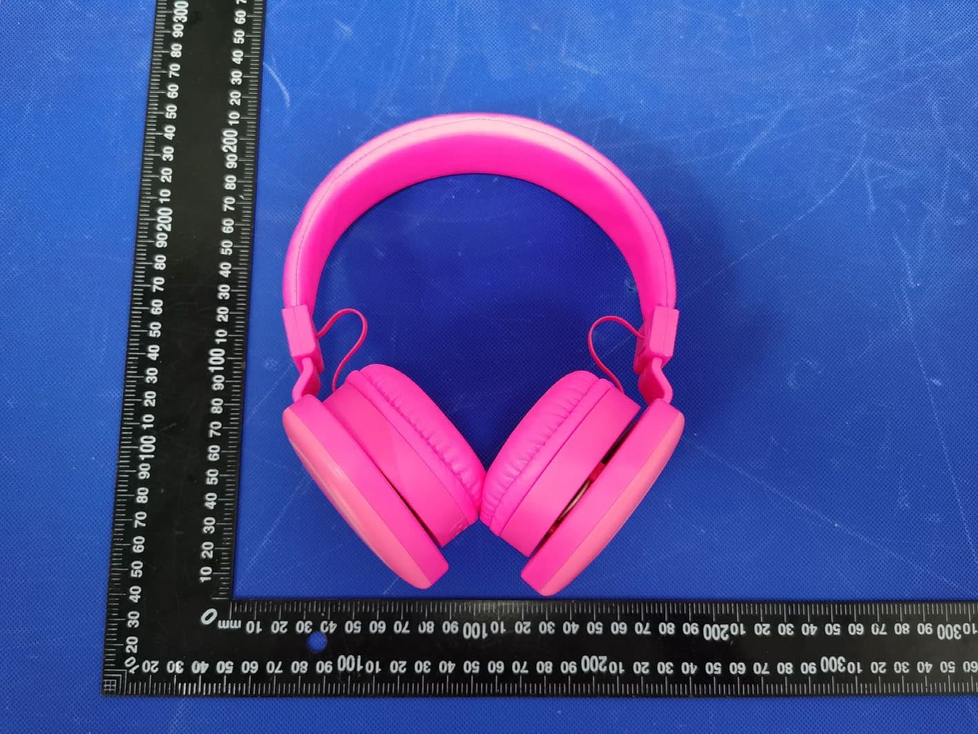
2AOW6-WMWLHP
Oct 14, 2024Bluetooth Headphone
Equipment Class
DSS - Part 15 Spread Spectrum Transmitter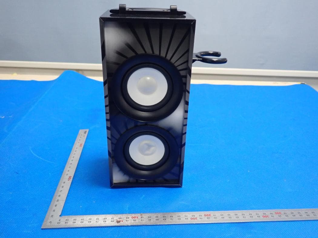
2AOW6BTP155
Aug 16, 2020Bluetooth Wooden Speaker
Equipment Class
DSS - Part 15 Spread Spectrum Transmitter
2AOW6-BTE2-FD
Apr 02, 2020IP Bluetooth Sport buds
Equipment Class
DSS - Part 15 Spread Spectrum Transmitter
2AOW6-HPBT010
Apr 02, 2020Kids Bluetooth and Wired Headphones
Equipment Class
DSS - Part 15 Spread Spectrum Transmitter