2AP3Q-ER307UWBSmart Tape
Guangdong Welland Technology Co., Ltd.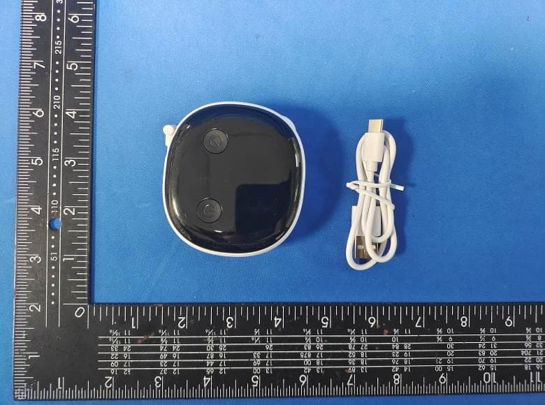
Click to zoom
Application Details
- Equipment Class
- DSS - Part 15 Spread Spectrum Transmitter
- Date of Grant
- Jul 18, 2024
- Application Purpose
- Original Equipment
- Date of Application
- Jul 18, 2024
- Equipment Note
- Smart Tape
- Frequency Range
- 2402.00000000 - 2480.00000000
- Country
- China
Documents & Files
Document Text
Text extracted from the exhibit documents filed with the FCC. Open a document above to read the original.
Users Manual
User Manual SMART BODY TAPE MEASURE Model:DH-SBT-019631 IMPORTANT SAFETY INSTRUCTIONS READ ALL INSTRUCTIONS CAREFULLY BEFORE USE. DO NOT use this device for any purpose other than outlined in this manual. The device is not intended for use by children under 12 years of age or younger or persons with reduced physical, sensory or cognitive capabilities unless they have been given supervision or instructions concerning the use of the device in a safe way and understood the hazards involved. DO NOT disassemble / modify the device. There are no user - serviceable parts inside. DO NOT subject or expose the device to extreme conditions: extreme temperatures beyond operating temperatures, high vibrations, dusty areas, humid conditions (including any liquid) or direct sunlight. DO NOT use excessive force on the gear or pull the tape over 150cm/60in. Stretching the tape or grinding the gear can damage the device permanently. DO NOT fold or twist the tape to avoid damaging the device. USE CAUTION when measuring neck circumference to avoid accidental choking. Retract the tape slowly to avoid injury. Do not heat, short-circuit, force discharge, encapsulate, deform, modify or dismantle the battery. Be aware of the risk of terminals of the battery-operated device or battery being short-circuited by metal objects. Do not get the device wet as it may damage the battery. Only use the provided charging cable and charger (DC 5V 0.5A, not included) to charge the device. Press Power Button to turn on the smart tape. When" "on the smart tape display turns solid, it indicates a successful connection. Press Power Button again to choose the unit (in/cm) you prefer. Once the device is connected, tap the body part name on the App. Press the locking pin until a “click" is heard, pull out the tape and wrap it around your target body part. Insert the locking pin into the receptacle until a “click" is heard. Press Retract Button to tighten the tape and press Confirm Button to get your measurement on the tape display or App. Tap “ Save " on the app to save all the measurements. This device complies with part 15 of the FCC Rules. Operation is subject to the following two conditions: (1) This device may not cause harmful interference, and (2) this device must acceptany interference received, including interference that may cause undesired operation. Warning: Changes or modifications not expressly approved by the party responsible for compliance could void the user's authority to operate the equipment. Note: This equipment has been tested and found to comply with the limits for a Class B digital device, pursuant to Part 15 of the FCC Rules. These limits are designed to provide reasonable protection against harmful interference in a residential installation. This equipment generates, uses and can radiate radio frequency energy and, if not installed and used in accordance with the instructions. may cause harmful interference to radio communica- tions. However, there is no guarantee that interference will not occur in a particular installation. If this equipment does cause harmful interference to radio or television reception, which can be determined by turning the equipment off and on, the user is encouraged to try to correct the interference by one or more of the following measures: -Reorient or relocate the receiving antenna. -Increase the separation between the equipment and receiver. -Connect the equipment into an outlet on a circuit different from that to which the receiver is connected. -Consult the dealer or an experienced radio/TV lechnician for help. RF Exposure Compliance This equipment complies with FCC radiation exposure limits set forth for an uncontrolled environment, This transmitter must not be co-located or operating inconjunction with any other antenna or transmitter. ISED Regulatory compliance This device contains licence-exempt transmitters that comply with Innovation. Science and Economic Development Canada's licence-exempt RSS(s). Operation is subject to the following two conditions: (1)This device may not cause interference. (2)This device must accept any interference, including interference that may cause undesired operation of the device. Le présent appareil est conforme aux CNR d'industrie Canada applicables aux appareils radio exempts de licence. L'exploitation est autorisée aux deux conditions suivantes: (1) l'appareil ne doit pas produire de brouillage, et (2) l'utilisateur de l'appareil doitaccepter tout brouillage radioélectrique subi, même si le brouillage est susceptibled'en compromettre le fonctionnement. This equipment complies with IC RSS-102 radiation exposure limits set forth for an uncontrolled environment. Cet équipement est conforme aux limites d'exposition aux radiations IC CNR-102 établies pour un environnement non contrôlé. Note: If the smart tape is turned on and left idle, it will shut off automatically after 20 seconds. After measuring, retract the tape for easy storage and to keep it in good condition. SAVE THESE INSTRUCTIONS CHARGING YOUR SMART TAPE INSTALLING THE APP & PAIRING WHAT'S IN THE BOX ABOUT YOUR SMART TAPE LED SCREEN PROMPTS INDICATING BATTERY LEVEL Smart Body Tape Measure x1 USB-C Charging Cable x1 (For charging only, not for data transfer) User Manual x1 Retract Button Press to retract the tape LED Display Confirm Button Press to confirm the measurement Press and hold for 3 seconds to zero out the measurement Power Button Press to turn on | Switch the units of measure Press and hold for 3 seconds to turn off Locking PinPress to unlock / lock) Tape Receptacle USB-C Charging Port Reset Button To reset the device, insert a pin (not included) into the Reset Button, press and release. 1. 2. 3. 4. 5. 6. 7. 8. LED DISPLAY Units: Switch via the Power Button Measurements The tape is not connected with app The tape is connected with app 75%-100%25%-50% 50%-70% Low battery. Charge the device. 0%-25% Charging Time: approx. 2 hours DC 5V 0.5A Charger (Not included) Power Sourc…
Text truncated - open the document above for the full version.
Attestation Statements
Guangdong Welland Technology Co., Ltd. No.85 MinKe East Road, MinYing Science and Technology Park, ShiQi District,Zhongshan China Federal Communications Commission Authorization and Evaluation Division Equipment Authorization Branch 7435 Oakland Mills Road Columbia, MD 21046 2024-7-19 To whom it may concern: We, Guangdong Welland Technology Co., Ltd., hereby certify that the equipment for which authorization is sought (FCC ID: 2AP3Q-ER307UWB) is not “covered” equipment prohibited from receiving an equipment authorization pursuant to § 2.903 of the FCC rules. We also certify that, as of the date of the filing of the application, we are not identified on the Covered List (https://www.fcc.gov/supplychain/coveredlist) as an entity producing “covered” equipment. By signing this form, we confirm the above and that we are aware of the application requirements listed under § 2.911(b) and (d)(5) and (6). The information provided in this letter is based on the referenced rule parts of Title 47 of the CFR as well as KDB 986446 D01. Sincerely, Signature Hillary Chan Manager Guangdong Welland Technology Co., Ltd. 62_[model] CoveredEqu_2.911(d)(5)(i) and (ii) - U, V03
Attestation Statements
Guangdong Welland Technology Co., Ltd. NO. 85 Minke East Road, Min Ying Science and Technology Park, Shiqi District, Zhongshan, Guangdong, China, 528400 Federal Communications Commission Authorization and Evaluation Division Equipment Authorization Branch 7435 Oakland Mills Road Columbia, MD 21046 2024/06/20 U.S. Agent Designation Guangdong Welland Technology Co., Ltd. acknowledges their consent for the following contact located in the United States to act as their agent for service of process for the equipment for which authorization is sought (FCC ID: 2AP3Q-ER307UWB): Name and company of U.S. agent: SELLER HELPER INC. Physical U.S. address of agent: 1312 17th Street # 1298, Denver, CO 80202, United States FRN of U.S. agent: 0033406737 Email address of U.S. agent: [email protected] SELLER HELPER INC. acknowledges their obligation to accept service of process on behalf of Guangdong Welland Technology Co., Ltd. Guangdong Welland Technology Co., Ltd. with the FRN [0027591197] accepts its obligation to maintain an agent for service of process in the United States for no less than one year after either the grantee has permanently terminated all marketing and importation of the applicable equipment within the U.S., or the conclusion of any Commission-related administrative or judicial proceeding involving the equipment, whichever is later. By signing this form, we confirm the above and that we are aware of the application requirements listed under § 2.911(d)(7). The information provided in this letter is based on the referenced rule parts of Title 47 of the CFR as well as KDB 986446 D01. An expiration date for this letter does not exist. In case the U.S. agent changes, the grantee is obligated to notify the FCC within 30 days via the granting TCB. Sincerely, Signature Hillary Chan Manager Guangdong Welland Technology Co., Ltd. Signature Fairy Lee Manager SELLER HELPER INC. 48_[mo del] US_Agent_2.911(d)(7) - U, V0 5
Cover Letter(s)
Guangdong Welland Technology Co., Ltd. Add: No.85 MinKe East Road, MinYing Science and Technology Park, ShiQi District,Zhongshan China Date: 2024-7-19 FCC ID: 2AP3Q-ER307UWB Dear Sir/Madam, We, Guangdong Welland Technology Co., Ltd. Hereby declares the following statement for Federal Communications Commission, PCB board, circuit, structure and internal of these model(s) are the same, Only model number is different for these model: Product name: Smart Tape Model no.: ER307UWB, ER307, DH-SBT-019631 Sincerely, Name/Title: Hillary Chan/Manager Company: Guangdong Welland Technology Co., Ltd. Address: No.85 MinKe East Road, MinYing Science and Technology Park, ShiQi District,Zhongshan China Phone: 86-760-2816 0369 Fax: 0760-28160370 E-Mail: [email protected]
Cover Letter(s)
CONFIDENTIALITY REQUEST for Certification Service in USA Federal Communication Commission Equipment Authorization Division, Application Processing Branch 7435 Oakland Mills Road Columbia, MD 21046 Date:<2024-7-19> Pursuant to Paragraphs §0.457 and 0.459 of the Commission’s Rules (47 C.F.R.) and Section §552(b)(4) of the Freedom of Information Act, we requests confidentiality for the following products: FCC ID Model name 2AP3Q-ER307UWB ER307UWB For the product stated above, we request that the following information be held confidential; Exhibits Long-Term Confidentiality Short-Term Confidentiality Short-Term Confidentiality Days External Photos Internal Photos Block Diagram Schematics Test Setup Photos User’s Manual Parts List Tune Up Operational Descriptions The long-term confidentiality exhibits contain our trade secrets and proprietary information that could be of benefit to our competitors. The short-term confidentiality on the basis of ensuring that business sensitive information remains confidential until the actual marketing of our new device. If you have any questions, please feel free to contact me at the address shown below. Sincerely, Name/Title: Hillary Chan/Manager Company: Guangdong Welland Technology Co., Ltd. Address: No.85 MinKe East Road, MinYing Science and Technology Park, ShiQi District,Zhongshan China Phone: 86-760-2816 0369 Fax: 0760-28160370 E-Mail: [email protected]
Cover Letter(s)
Guangdong Welland Technology Co., Ltd. No.85 MinKe East Road, MinYing Science and Technology Park, ShiQi District,Zhongshan China Federal Communications Commission Authorization and Evaluation Division Equipment Authorization Branch 7435 Oakland Mills Road Columbia, MD 21046 2024-7-19 To whom it may concern: We, the undersigned, hereby authorize Eurofins Product Service GmbH to act on our behalf in all matters relating to applications for equipment authorization FCC ID: 2AP3Q-ER307UWB including the signing of all documents related to these matters. Any and all acts carried out by Eurofins Product Service GmbH on our behalf shall have the same effect as acts of our own. By signing this application form, we agree to Eurofins’ current valid General Terms and Conditions (AGB),Testing and Certification Regulations (PZO) which can be viewed on following website www.eurofins.de/ee or retrieved on request. We also hereby certify that no party to this application is subject to a denial of benefits, including FCC benefits, pursuant to Section 5301 of the Anti-Drug Abuse Act of 1988, 21 U.S.C. 862. Sincerely, Name/Title: Hillary Chan/Manager Company: Guangdong Welland Technology Co., Ltd. Address: No.85 MinKe East Road, MinYing Science and Technology Park, ShiQi District,Zhongshan China Phone: 86-760-2816 0369 Fax: 0760-28160370 E-Mail: [email protected]
External Photos
FCC ID: 2AP3Q-ER307UWB External Photos of the EUT FCC ID: 2AP3Q-ER307UWB FCC ID: 2AP3Q-ER307UWB
ID Label/Location Info
Label and Location Size: L: 2.0cm*W: 1.0cm Label and Location FCC ID : 2AP3Q-ER307UWB
Internal Photos
FCC ID: 2AP3Q-ER307UWB Internal Photos of the EUT FCC ID: 2AP3Q-ER307UWB FCC ID: 2AP3Q-ER307UWB ANT
RF Exposure Info
RF Exposure evaluation FCC ID: 2AP3Q-ER307UWB 1.1. Applicable Standard According to §1.1307(b)(1), systems operating under the provisions of this section shall be operated in a manner that ensures that the public is not exposed to radio frequency energy level in excess of the Commission’s guidelines. According to §1.1310 and §2.1093 RF exposure requirement KDB447498 v06: Mobile and Portable Devices RF Exposure Procedures and Equipment Authorization Policies 1.2. Requirement According to KDB447498 D01 General RF Exposure Guidance v06 Section 4.3.1 Standalone SAR test exclusion considerations: “Unless specifically required by the published RF exposure KDB procedures, standalone 1-g head or body and 10-g extremity SAR evaluation for general population exposure conditions, by measurement or numerical simulation, is not required when the corresponding SAR Test Exclusion Threshold condition, listed below, is satisfied. These test exclusion conditions are based on source-based time-averaged maximum conducted output power of the RF channel requiring evaluation, adjusted for tune-up tolerance, and the minimum test separation distance required for the exposure conditions.22 The minimum test separation distance is determined by the smallest distance from the antenna and radiating structures or outer surface of the device, according to the host form factor, exposure conditions and platform requirements, to any part of the body or extremity of a user or bystander (see 5) of section 4.1). To qualify for SAR test exclusion, the test separation distances applied must be fully explained and justified by the operating configurations and exposure conditions of the transmitter and applicable host platform requirements, typically in the SAR measurement or SAR analysis report, according to the required published RF exposure KDB procedures. When no other RF exposure testing or reporting is required, a statement of justification and compliance must be included in the equipment approval, in lieu of the SAR report, to qualify for the SAR test exclusion. When required, the device specific conditions described in the other published RF exposure KDB procedures must be satisfied before applying these SAR test exclusion provisions; for example, handheld PTT two-way radios, handsets, laptops & tablets etc.23 “ [(max. power of channel, including tune-up tolerance, mW)/ (min. test separation distance, mm)] · [√f (GHz)] ≤ 3.0 for 1-g SAR and ≤ 7.5 for 10-g extremity SAR, where: • f (GHz) is the RF channel transmit frequency in GHz • Power and distance are rounded to the nearest mW and mm before calculation • The result is rounded to one decimal place for comparison • 3.0 and 7.5 are referred to as the numeric thresholds in the step 2 below The test exclusions are applicable only when the minimum test separation distance is ≤ 50 mm and for transmission frequencies between 100 MHz and 6 GHz. When the minimum test separation distance is < 5 mm, a distance of 5 mm according to 5) in section 4.1 is applied to determine SAR test exclusion. 1.3. Manufacturing tolerance GFSK (Peak) Channel Channel 0 Channel 39 Channel 78 Target (dBm) -2.0 -2.0 -3.0 Tolerance ±(dB) 1.0 1.0 1.0 π/4DQPSK (Peak) Channel Channel 0 Channel 39 Channel 78 Target (dBm) 0.0 -2.0 -2.0 Tolerance ±(dB) 1.0 1.0 1.0 8-DPSK (Peak) Channel Channel 0 Channel 39 Channel 78 Target (dBm) 0.0 -2.0 -2.0 Tolerance ±(dB) 1.0 1.0 1.0 Page 2 of 2 2. E v a l u a t i o n R e s u l t Evaluation Results Band/Mode f (GHz) Antenna Distance (mm) RF output power (including tune-up tolerance) SAR Test Exclusion Threshold SAR Test Exclusion dBm mW BT 2.450 5 1.0 1.2589 0.3941<3.0 Yes 3. C o n c l u s i o n The measurement results comply with the FCC Limit per 47 CFR 2.1093 for the uncontrolled RF Exposure and SAR Exclusion Threshold per KDB 447498 v06 .....................End of Report.........................
Test Report
1. Antenna Description: Antenna type PCB antenna Model ER307UWB Frequency range 2400-2500MHz Manufacturer Guangdong Welland Technology Co., Ltd. ANT Peak Gain 0.72 dBi 2. Antenna Photo: Length :4.12mm Width:1.35mm Length :10.82mm Length :9.89mm 3. Test Equipment & Conditions 3.1 Test instrument VSWR is tested using Agilent E5071B connected to a hand mechanism, and the status is free space. 3.2 Test environment and methods 4.Antenna Radiation Pattern 2400MHz 2450MHz 2500MHz
Test Report
Shenzhen CTA Testing Technology Co., Ltd. Room 106, Building 1, Yibaolai Industrial Park, Qiaotou Community, Fuhai Street, Bao’an District, Shenzhen, China Shenzhen CTA Testing Technology Co., Ltd. Room 106, Building 1, Yibaolai Industrial Park, Qiaotou Community, Fuhai Street, Bao’an District, Shenzhen, China Tel:+86-755 2322 5875 E-mail:[email protected] Web:http://www.cta-test.cn FCC PART 15 SUBPART C TEST REPORT FCC PART 15.247 Report Reference No. ..................... : FCC ID............................................. : CTA24061400201 2AP3Q-ER307UWB Compiled by ( position+printed name+signature) . : File administrators Jinghua Xiao Supervised by ( position+printed name+signature) . : Project Engineer Lushan Kong Approved by ( position+printed name+signature) . : RF Manager Eric Wang Date of issue .................................... : Jun. 18, 2024 Testing Laboratory Name .............. : Shenzhen CTA Testing Technology Co., Ltd. Address ............................................ : Room 106, Building 1, Yibaolai Industrial Park, Qiaotou Community, Fuhai Street, Bao‘an District, Shenzhen, China Applicant’s name ............................ : Guangdong Welland Technology Co., Ltd. Address ............................................ : No.85 MinKe East Road, MinYing Science and Technology Park, ShiQi District, Zhongshan, Guangdong, China, 528400 Test specification ........................... : Standard ........................................... : FCC Part 15.247 Shenzhen CTA Testing Technology Co., Ltd. All rights reserved. This publication may be reproduced in whole or in part for non-commercial purposes as long as the Shenzhen CTA Testing Technology Co., Ltd. is acknowledged as copyright owner and source of the material. Shenzhen CTA Testing Technology Co., Ltd. takes no responsibility for and will not assume liability for damages resulting from the reader's interpretation of the reproduced material due to its placement and context. Test item description ..................... : Smart Tape Trade Mark ....................................... : N/A Manufacturer .................................... : Guangdong Welland Technology Co., Ltd. Model/Type reference ...................... : ER307UWB Listed Models .................................. : ER307, DH-SBT-019631 Modulation ....................................... : GFSK, Π/4DQPSK, 8DPSK Frequency ......................................... From 2402MHz to 2480MHz Rating ............................................... : DC 3.7V From battery and DC 5.0V From external circuit Result ............................................... : PASS Report No.: CTA24061400201 Page 2 of 49 Shenzhen CTA Testing Technology Co., Ltd. Room 106, Building 1, Yibaolai Industrial Park, Qiaotou Community, Fuhai Street, Bao’an District, Shenzhen, China Tel:+86-755 2322 5875 E-mail:[email protected] Web:http://www.cta-test.cn T E S T R E P O R T Equipment under Test : Smart Tape Model /Type : ER307UWB Listed Models : ER307, DH-SBT-019631 Applicant : Guangdong Welland Technology Co., Ltd. Address : No.85 MinKe East Road, MinYing Science and Technology Park, ShiQi District, Zhongshan, Guangdong, China, 528400 Manufacturer : Guangdong Welland Technology Co., Ltd. Address : No.85 MinKe East Road, MinYing Science and Technology Park, ShiQi District, Zhongshan, Guangdong, China, 528400 Test Result: PASS The test report merely corresponds to the test sample. It is not permitted to copy extracts of these test result without the written permission of the test laboratory. Report No.: CTA24061400201 Page 3 of 49 Shenzhen CTA Testing Technology Co., Ltd. Room 106, Building 1, Yibaolai Industrial Park, Qiaotou Community, Fuhai Street, Bao’an District, Shenzhen, China Tel:+86-755 2322 5875 E-mail:[email protected] Web:http://www.cta-test.cn Contents 1 T E S T S T A N D A R D S ................................................................. 4 2 S U M M A R Y ............................................................................ 5 2.1 General Remarks 5 2.2 Product Description 5 2.3 Equipment Under Test 5 2.4 Short description of the Equipment under Test (EUT) 5 2.5 EUT operation mode 6 2.6 Block Diagram of Test Setup 6 2.7 Related Submittal(s) / Grant (s) 6 2.8 Modifications 6 3 T E S T E N V I R O N M E N T .............................................................. 7 3.1 Address of the test laboratory 7 3.2 Test Facility 7 3.3 Environmental conditions 7 3.4 Summary of measurement results 8 3.5 Statement of the measurement uncertainty 8 3.6 Equipments Used during the Test 9 4 T E S T C O N D I T I O N S A N D R E S U L T S ........................................... 11 4.1 AC Power Conducted Emission 11 4.2 Radiated Emission 14 4.3 Maximum Peak Output Power 20 4.4 20dB Bandwidth 21 4.5 Frequency Separation 25 4.6 Number of hopping frequency 27 4.7 Time of Occupancy (Dwell Time) 29 4.8 Out-of-band Emissions 33 4.9 Pseudorandom Frequency Hopping Sequence 42 4.10 Antenna Requirement 43 5 T E S T S E T U P P H O T O S O F T HE E U T ......................................... 44 6 P H O T O S O F T H E E U T ........................................................... 45 Report No.: CTA24061400201 Page 4 of 49 Shenzhen CTA Testing Technology Co., Ltd. Room 106, Building 1, Yibaolai Industrial Park, Qiaotou Community, Fuhai Street, Bao’an District, Shenzhen, China Tel:+86-755 2322 5875 E-mail:[email protected] Web:http://www.cta-test.cn 1 T E S T S T A N D A R D S The tests were performed according to following standards: FCC Rules Part 15.247: Frequency Hopping, Direct Spread Spectrum and Hybrid Systems that are in operation within the bands of 902-928 MHz, 2400-2483.5 MHz, and 5725-5850 MHz. ANSI C63.10-2013: American National Standard for Testing Unlicensed Wireless Devices Report No.: CTA24061400201 Page 5 of 49 Shenzhen CTA Testing Technology Co., Ltd. Room 106, Building 1, Yibaolai Industrial Park, Qiaotou Community, Fuhai Street, Bao’an District, Shenzhen, China Tel:+86-755…
Text truncated - open the document above for the full version.
Test Report
Report No.: CTA24061400201 Page 37 of 49 Shenzhen CTA Testing Technology Co., Ltd. Room 106, Building 1, Yibaolai Industrial Park, Qiaotou Community, Fuhai Street, Bao’an District, Shenzhen, China Tel:+86-755 2322 5875 E-mail:[email protected] Web:http://www.cta-test.cn 8DPSK (CH00) 8DPSK (CH39) reference reference 30MHz-1G 30MHz-1G 1G-25G 1G-25G Report No.: CTA24061400201 Page 38 of 49 Shenzhen CTA Testing Technology Co., Ltd. Room 106, Building 1, Yibaolai Industrial Park, Qiaotou Community, Fuhai Street, Bao’an District, Shenzhen, China Tel:+86-755 2322 5875 E-mail:[email protected] Web:http://www.cta-test.cn 8DPSK (CH78) reference 30MHz-1G 3G-25G Report No.: CTA24061400201 Page 39 of 49 Shenzhen CTA Testing Technology Co., Ltd. Room 106, Building 1, Yibaolai Industrial Park, Qiaotou Community, Fuhai Street, Bao’an District, Shenzhen, China Tel:+86-755 2322 5875 E-mail:[email protected] Web:http://www.cta-test.cn Band-edge Measurements for RF Conducted Emissions: GFSK Left Band edge hoping off Right Band edge hoping off Left Band edge hoping on Right Band edge hoping on Report No.: CTA24061400201 Page 40 of 49 Shenzhen CTA Testing Technology Co., Ltd. Room 106, Building 1, Yibaolai Industrial Park, Qiaotou Community, Fuhai Street, Bao’an District, Shenzhen, China Tel:+86-755 2322 5875 E-mail:[email protected] Web:http://www.cta-test.cn π/4DQPSK Left Band edge hoping off Right Band edge hoping off Left Band edge hoping on Right Band edge hoping on Report No.: CTA24061400201 Page 41 of 49 Shenzhen CTA Testing Technology Co., Ltd. Room 106, Building 1, Yibaolai Industrial Park, Qiaotou Community, Fuhai Street, Bao’an District, Shenzhen, China Tel:+86-755 2322 5875 E-mail:[email protected] Web:http://www.cta-test.cn 8DPSK Left Band edge hoping off Right Band edge hoping off Left Band edge hoping on Right Band edge hoping on Report No.: CTA24061400201 Page 42 of 49 Shenzhen CTA Testing Technology Co., Ltd. Room 106, Building 1, Yibaolai Industrial Park, Qiaotou Community, Fuhai Street, Bao’an District, Shenzhen, China Tel:+86-755 2322 5875 E-mail:[email protected] Web:http://www.cta-test.cn 4.9 Pseudorandom Frequency Hopping Sequence TEST APPLICABLE For 47 CFR Part 15C section 15.247 (a) (1) requirement: Frequency hopping systems shall have hopping channel carrier frequencies separated by a minimum of 25 kHz or the 20 dB bandwidth of the hop-ping channel, whichever is greater. Alternatively, frequency hopping systems operating in the 2400–2483.5 MHz band may have hopping channel carrier frequencies that are separated by 25 kHz or two-thirds of the 20 dB bandwidth of the hopping channel, whichever is greater, provided the systems operate with an output power no greater than 125 mW. The system shall hop to channel frequencies that are selected at the system hopping rate from a pseudo randomly ordered list of hopping frequencies. Each frequency must be used equally on the average by each transmitter. The system receivers shall have input bandwidths that match the hop-ping channel bandwidths of their corresponding transmitters and shall shift frequencies in synchronization with the transmitted signals. EUT Pseudorandom Frequency Hopping Sequence Requirement The pseudorandom frequency hopping sequence may be generated in a nice-stage shift register whose 5 th and 9 th stage outputs are added in a modulo-two addition stage. And the result is fed back to the input of the first stage. The sequence begins with the first one of 9 consecutive ones, for example: the shift register is initialized with nine ones. ● Number of shift register stages:9 ● Length of pseudo-random sequence:29-1=511 bits ● Longest sequence of zeros:8(non-inverted signal) An example of pseudorandom frequency hopping sequence as follows: Each frequency used equally one the average by each transmitter. The system receiver have input bandwidths that match the hopping channel bandwidths of their corresponding transmitter and shift frequencies in synchronization with the transmitted signals. Report No.: CTA24061400201 Page 43 of 49 Shenzhen CTA Testing Technology Co., Ltd. Room 106, Building 1, Yibaolai Industrial Park, Qiaotou Community, Fuhai Street, Bao’an District, Shenzhen, China Tel:+86-755 2322 5875 E-mail:[email protected] Web:http://www.cta-test.cn 4.10 Antenna Requirement Standard Applicable For intentional device, according to FCC 47 CFR Section 15.203, an intentional radiator shall be designed to ensure that no antenna other than that furnished by the responsible party shall be used with the device. And according to FCC 47 CFR Section 15.247 (c), if transmitting antennas of directional gain greater than 6dBi are used, the power shall be reduced by the amount in dB that the directional gain of the antenna exceeds 6dBi. Refer to statement below for compliance The manufacturer may design the unit so that the user can replace a broken antenna, but the use of a standard antenna jack or electrical connector is prohibited. Further, this requirement does not apply to intentional radiators that must be professionally installed. Antenna Connected Construction The maximum gain of antenna was 0.72 dBi. Remark:The antenna gain is provided by the customer , if the data provided by the customer is not accurate, Shenzhen CTA Testing Technology Co., Ltd. does not assume any responsibility. Report No.: CTA24061400201 Page 44 of 49 Shenzhen CTA Testing Technology Co., Ltd. Room 106, Building 1, Yibaolai Industrial Park, Qiaotou Community, Fuhai Street, Bao’an District, Shenzhen, China Tel:+86-755 2322 5875 E-mail:[email protected] Web:http://www.cta-test.cn 5 T e s t S e t u p P h o t o s o f t h e E U T Report No.: CTA24061400201 Page 45 of 49 Shenzhen CTA Testing Technology Co., Ltd. Room 106, Building 1, Yibaolai Industrial Park, Qiaotou Community, Fuhai Street, Bao’an District, Shenzhen, China Tel:+86-755 2322 5875 E-mail:[email protected] Web:http://www.cta-test.cn 6 P h o t o s o f t h e E U T Report No.: CTA24061400201 Page 46 of 49 Shenzhen CTA Testi…
Text truncated - open the document above for the full version.
Test Setup Photos
FCC ID: 2AP3Q-ER307UWB Test Setup Photos of the EUT
Contact Information
Applicant
Hillary Chan(Sales Manager)
Test Firm
SHENZHEN CTA TESTING TECHNOLOGY CO., LTD.Eric Wang
[email protected]+86 755 2322 5875
Technical Specifications
| # | Rule Parts | Frequency Range | Power Output |
|---|---|---|---|
| 1 | 15C | 2.40 GHz - 2.48 GHz | 800.00 µW |
Other Applications from Guangdong Welland Technology Co., Ltd.
2AP3Q-FG2415WB
Jul 24, 2026Smart Scale
Equipment Class
DTS - Digital Transmission System
2AP3Q-FG2504WB-A
Apr 29, 2026Smart Body Fat Scale
Equipment Class
DTS - Digital Transmission System
2AP3Q-KG2458ULB
Apr 21, 2026Kitchen scale
Equipment Class
DTS - Digital Transmission System
2AP3Q-FG450WB-A
Apr 21, 2026Smart Body Fat Scale
Equipment Class
DTS - Digital Transmission System
2AP3Q-FI2502ULB
Mar 09, 2026Smart Body Fat Scale
Equipment Class
DTS - Digital Transmission System