2AP3QIGRIP2Smart Scale
Guangdong Welland Technology Co., Ltd.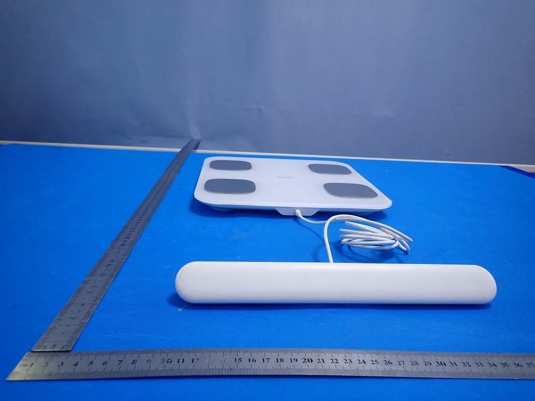
Click to zoom
Application Details
- Equipment Class
- DTS - Digital Transmission System
- Date of Grant
- Dec 21, 2020
- Application Purpose
- Original Equipment
- Date of Application
- Dec 21, 2020
- Equipment Note
- Smart Scale
- Frequency Range
- 2402.00000000 - 2480.00000000
- Country
- China
Documents & Files
Document Text
Text extracted from the exhibit documents filed with the FCC. Open a document above to read the original.
Users Manual
Smart Body fat scale Instruction Manual Scan the QR Code to download APP Thanks for choosing Smart body Scale. This fully body composition scale can help you conveniently measure body weight, Body balance, BMI, Body fat rate, Visceral fat, Body water, Skeletal muscle rate, Muscle mass, bone mass, Protein, BMR, Body age and etc; IMPORTANT: Please read these instructions in this manual carefully before using the device. Failure to comply with the instructions given in the manual or using this scale in ways other than the ones mentioned in this manual may result in injury to yourself or damage to the scale. (Fitdays APP functions) Weight Body fat Visceral fat Protein amount BMI Muscle weight Bone mass Moisture BME Degree of obesity Body age Muscle Standard weight Without fat BFR Protein rate Subcutaneous fat Height record (<16 years old) Partial body fat Partial muscle rate INDICATION SYMBOLS LO Low battery - Please replace 4xAAA new batteries; Err Overload C An error has occurred during measurement. Step off the scales and step onto them again to repeat the measuring process. WHAT’S IN THE PACKAGE 1 X Smart body fat scale 1 X User manual 4X AAA batteries Product Structure WARNING DO NOT use with medical implants such as pacemakers. DO NOT stand on the edge of the scale or jump on it; DO NOT overload the scale(Max.180kg) DO NOT drop scale or droop and objects on it as this may damage the sensors. DO NOT immerse the scale in water or use chemical cleaning agents. Clean the scale with slightly damp cloth. Not recommended for pregnant women. Not recommended for infants, toddlers, and children under 10 years of age. Any measurement obtained using this device is for reference only and should not be considered as a medical opinion. Consult your primary care doctor or physician before making changes to your diet, exercise plan or physical activities. Always place the scale on a hard, dry and flat surface before measurement. Make sure your feet are dry before stepping on the scale. Connect the batteries in accordance with the correct polarities indicated. Remove batteries if the scale is not be use for a prolonged period of time. SPECIFICATION Weight unit:kg/lb/st (switch the units by APP) Weight limit: 6kg-180kg Power Supply: 4xAAA Account number: No limitation (each account can add 24 persons) 5. Handle bar 4. Connecting cable 3. LED display 2. Electrode metal plate 1. Glass platform Baby mode: Allow you to scale the weight of baby Height record: Allow you to record the height info under 16 years old Operating temperature: 10-40 0 C Operation humidity: 20%-90% Support Devices: iOS 8.0 or higher Android 6.0 or higher Install Fitdays App 1. Search “Fitdays” in Apple Store or Google Play or scan the QR Code below: 2. Download and install the App on your device. 3. The App icon will appear on your phone or tablet after the installation is completed. HOW TO USE FITDAYS APP 1. Insert 4xAAA batteries. Place the scale on the hard, flat ground. 2. Turn on the Bluetooth on your smart phone or tablet. 3. Register your own ID by email or social media account. 3 X √ 4. Add personal data and confirm OK; Note: Enter the wrong gender, age, height info may result in measurement being inaccurate. 5. Pair the scale through Bluetooth. Click Mine ----> My device find the scale “icomon” now your phone is connected with the scale; 6. Tap your foot on the scales to activate the display. Wait until the display shows “0.0”(kg/lb/st). Make sure the connecting cable is well connected with scale and handle bar. 7. Step on the scale with BARE feet to turn the scale on; At the same time, make sure your fingers are full touch with the four electrodes on handle bar(Pay attention for Left & Right direction), at the same time, stand on each two electrode metal plate with bare feet as below indication photos; X √ X X Note: If stepping on the scale with socks, or connecting cable not connect with scale and handle bar well enough, only weight and BMI will be measured and displayed on the main page. To get complete data, please step on the scale with bare feet. 8. The number on the display is flashing when the scale is weighing and analyzing. Continue to stand on the scale until scale finish showing 0.0.0., your phone has received all the data from the scale. 9. You can click More Data to read more Parameter data. 10. You can find the analyzing report on Body Weight, BMI, BFR, Muscle, Bone Mass etc. (see full details on page 1 RECORDED PARAMETERS). When you click Record, you can see your long-term track chat form. 11. Add, switch user by click , or click Me--> Manage users, then add personal data. The Smart Scale can recognize which user is step on it and remind user to switch the correct user. Each account can support 24users; 11, Weighing baby: click + -->Baby Mode. Step on the scale by you own, after scale scale gets your weight, and then hold the baby to get the weight of baby. TROUBLE SHOOTING GUIDE 1. Bluetooth not connected The scale and smart phone must be both have Bluetooth on. Check the OS version of your smart phone, it must be iOS 8.0 or higher/Android 4.3 higher. Click Me--->My device find the scale ‘icomon’. 2. No body fat data measured when weighing User must be bare foot to measure the body fat. Make sure your feet and the scale are both dry. Scale not finishing weighing when the number display is flashing (Keep standing on the scale around 10 second until the number on the display stops flashing). Bluetooth is not turned on. Bluetooth is paired with a difference scale. 3. The scale is producing inconsistent weight. Check whether the scale is on a hard, flat surface. Check each sensor foot on the back to make sure nothing is stuck to the bottom of it. Remove the batteries to restart the scale; 4. The App is display the incorrect fat-muscle ratio The body parameter setting is incorrect, check to make sure you entered the correct gender, height, and age. 5. How do I re-calibrate the scale after moving it or change the b…
Text truncated - open the document above for the full version.
Cover Letter(s)
Guangdong Welland Technology Co., Ltd. Dec. 18, 2020 Office of Engineering Technology Federal Communications Commission 7435 Oakland Mills Road Columbia, MD 21046 USA Subject: Explanation of differences between product types FCC ID : 2AP3QIGRIP2 Model Number: igrip2, igrip3, FG2001B-A, FG2001B-C, FI2001B-A, FI2001B-C, FG2001B, FI2001B To Whom It May Concern: We, The Guangdong Welland Technology Co., Ltd hereby declare that the models are identical except the model name. Except for the different above, no other modification is performed. Sincerely, Signature: Guangdong Welland Technology Co., Ltd. Contact person: Hillary Chan
Cover Letter(s)
Guangdong Welland Technology Co., Ltd. Agent Authorization Company: Guangdong Welland Technology Co., Ltd Address: No.85 MinKe East Road, MinYing Science and Technology Park, ShiQi District, Zhongshan, China Product Name: Smart Scale Model Number(s): igrip2, igrip3, FG2001B-A, FG2001B-C, FI2001B-A, FI2001B-C, FG2001B, FI2001B Product Description: Smart Scale We authorize MiCOM Labs Inc., 575 Boulder Court, Pleasanton, California 94566, USA, to act on our behalf on all matters concerning the certification of above named equipment. We declare that MiCOM Labs Inc. is allowed to forward all information related to the approval and certification of equipment to the regulatory agencies as required and to discuss any issues concerning the approval application. Any and all acts carried out by MiCOM Labs on our behalf shall have the same effect as acts of our own. Signature: Date: 2020-12-18 Name: Hillary Chan Company: Guangdong Welland Technology Co., Ltd.
Cover Letter(s)
Guangdong Welland Technology Co., Ltd. Office of Engineering Technology Federal Communications Commission 7435 Oakland Mills Road Columbia, MD 21046 USA Date: 2020-12-16 Subject; Request for Confidentiality FCC ID: 2AP3QIGRIP2 To Whom It May Concern, Pursuant to the provisions of the Commission’s rules Title 47 Sections §0.457 and §0.459, we are requesting the Commission to withhold the following attachment(s) as confidential documents from public disclosure indefinitely. These documents contain detailed system and equipment descriptions and are considered as proprietary information in operation of the equipment. The public disclosure of these documents might be harmful to our company and would give competitors an unfair advantage in the market. Schematic Diagram Block Diagram Parts List Operational Description Tune-up Procedure In additional to above mentioned documents, in order to comply with the marketing regulations in Title 47 CFR §2.803 and the importation rules in Title 47 CFR §2.1204, while ensuring that business sensitive information remains confidential until the actual marketing of newly authorized devices, we request Short Term Confidentiality of the following attachment(s); External Photos Test Setup Photos Internal Photos User Manual For 45 days, pursuant to Public Notice DA 04-1705. OR For 180 days pursuant to KDB 726920 D01. It is our understanding that all measurement test reports, FCC ID label format and correspondence during the certification review process cannot be granted as confidential documents and this information will be available for public review once the grant of equipment authorization is issued. Sincerely Guangdong Welland Technology Co., Ltd. Contact person: Hillary Chan
External Photos
External Photos TOP VIEW OF EUT BOTTOM VIEW OF EUT FRONT VIEW OF EUT BACK VIEW OF EUT LEFT VIEW OF EUT RIGHT VIEW OF EUT
ID Label/Location Info
FCC ID Label Location FCC ID: 2AP3QIGRIP2
Internal Photos
Internal Photos OPEN VIEW OF EUT-1 OPEN VIEW OF EUT-2 INTERNAL VIEW OF EUT-1 INTERNAL VIEW OF EUT-2 INTERNAL VIEW OF EUT-3 INTERNAL VIEW OF EUT-4 BT Antenna INTERNAL VIEW OF EUT-5 INTERNAL VIEW OF EUT-6
RF Exposure Info
RF EXPOSURE EVALUATION 1. PRODUCT INFORMATION Product Description Smart scale Model Name igrip2, igrip3, FG2001B-A, FG2001B-C, FI2001B-A, FI2001B-C, FG2001B, FI2001B FCC ID 2AP3QIGRIP2 2. EVALUATION METHOD According to 447498 D01 General RF Exposure Guidance v05 The 1-g and 10-g SAR test exclusion thresholds for 100 MHz to 6 GHz at test separation distances ≤ 50 mm are determined by: [(max. power of channel, including tune-up tolerance, mW)/(min. test separation distance, mm)] ·[√f(GHz)] ≤ 3.0 for 1-g SAR and ≤ 7.5 for 10-g extremity SAR. Where f(GHz) is the RF channel transmit frequency in GHz Power and distance are rounded to the nearest mW and mm before calculation 3. CALCULATION BLE: P t =0.747dBm=1.19mW The value of the Maximum output power P t is referred to the test report of the CFR47 §15.247. The result for RF exposure evaluation SAR=(1.19mW /5mm) .[√2.402GHz)]= 0.37<3.0 for 1-g SAR and ≤ 7.5 for 10-g extremity SAR. 4. CONCLUSION The SAR evaluation is not required.
Test Report
Page 1 of 46 FCC Test Report Report No.: AGC06164201202FE02 FCC ID : 2AP3QIGRIP2 APPLICATION PURPOSE : Original Equipment PRODUCT DESIGNATION : Smart scale BRAND NAME : N/A MODEL NAME : igrip2, igrip3, FG2001B-A, FG2001B-C, FI2001B-A, FI2001B-C, FG2001B, FI2001B APPLICANT : Guangdong Welland Technology Co., Ltd DATE OF ISSUE : Dec. 16, 2020 STANDARD(S) : FCC Part 15.247 REPORT VERSION : V1.0 Attestation of Global Compliance (Shenzhen) Co., Ltd Report No.: AGC06164201202FE02 Page 2 of 46 REPORT REVISE RECORD Report Version Revise Time Issued Date Valid Version Notes V1.0 / Dec. 16, 2020 Valid Initial Release Report No.: AGC06164201202FE02 Page 3 of 46 TABLE OF CONTENTS 1. VERIFICATION OF COMPLIANCE ............................................................................................................... 4 2. GENERAL INFORMATION ............................................................................................................................ 5 2.1. PRODUCT DESCRIPTION ...................................................................................................................... 5 2.2. TABLE OF CARRIER FREQUENCYS ..................................................................................................... 5 2.3. RELATED SUBMITTAL(S)/GRANT(S) .................................................................................................... 6 2.4. TEST METHODOLOGY ........................................................................................................................... 6 2.5. SPECIAL ACCESSORIES ....................................................................................................................... 6 2.6. EQUIPMENT MODIFICATIONS .............................................................................................................. 6 2.7. ANTENNA REQUIREMENT ..................................................................................................................... 6 3. MEASUREMENT UNCERTAINTY ................................................................................................................. 7 4. DESCRIPTION OF TEST MODES ................................................................................................................. 8 5. SYSTEM TEST CONFIGURATION ............................................................................................................... 9 5.1. CONFIGURATION OF TESTED SYSTEM ............................................................................................... 9 5.2. EQUIPMENT USED IN TESTED SYSTEM .............................................................................................. 9 5.3. SUMMARY OF TEST RESULTS .............................................................................................................. 9 6. TEST FACILITY ........................................................................................................................................... 10 7. PEAK OUTPUT POWER ............................................................................................................................. 11 7.1. MEASUREMENT PROCEDURE ............................................................................................................ 11 7.2. TEST SET-UP (BLOCK DIAGRAM OF CONFIGURATION) ................................................................... 11 7.3. LIMITS AND MEASUREMENT RESULT ............................................................................................... 12 8. 6 DB BANDWIDTH ...................................................................................................................................... 14 8.1. MEASUREMENT PROCEDURE ........................................................................................................... 14 8.2. TEST SET-UP (BLOCK DIAGRAM OF CONFIGURATION) .................................................................. 14 8.3. LIMITS AND MEASUREMENT RESULTS ............................................................................................. 14 9. CONDUCTED SPURIOUS EMISSION ........................................................................................................ 16 9.1. MEASUREMENT PROCEDURE ........................................................................................................... 16 9.2. TEST SET-UP (BLOCK DIAGRAM OF CONFIGURATION) .................................................................. 16 9.3. MEASUREMENT EQUIPMENT USED .................................................................................................. 16 9.4. LIMITS AND MEASUREMENT RESULT ............................................................................................... 16 10. MAXIMUM CONDUCTED OUTPUT POWER SPECTRAL DENSITY ....................................................... 24 10.1. MEASUREMENT PROCEDURE ......................................................................................................... 24 10.2. TEST SET-UP (BLOCK DIAGRAM OF CONFIGURATION) ................................................................ 24 10.3. MEASUREMENT EQUIPMENT USED ................................................................................................ 24 10.4. LIMITS AND MEASUREMENT RESULT ............................................................................................. 24 11. RADIATED EMISSION ............................................................................................................................... 26 11.1. MEASUREMENT PROCEDURE ......................................................................................................... 26 11.2. TEST SETUP ....................................................................................................................................... 27 11.3. LIMITS AND MEASUREMENT RESULT ............................................................................................. 28 11.4. TEST RESULT .......................................…
Text truncated - open the document above for the full version.
Test Setup Photos
Test Setup Photos RADIATED EMISSION TEST SETUP BELOW 1GHZ RADIATED EMISSION TEST SETUP ABOVE 1GHZ CONDUCTED TEST SETUP
Contact Information
Applicant
Hillary Chan(Sales Manager)
Technical Contact
Test Firm
Attestation of Global Compliance (Shenzhen) Co., LDoris Li
[email protected]+86-755-25234088
Technical Specifications
| # | Rule Parts | Frequency Range | Power Output |
|---|---|---|---|
| 1 | 15C | 2.40 GHz - 2.48 GHz | 1.20 mW |
Other Applications from Guangdong Welland Technology Co., Ltd.
2AP3Q-FG2415WB
Jul 24, 2026Smart Scale
Equipment Class
DTS - Digital Transmission System
2AP3Q-FG2504WB-A
Apr 29, 2026Smart Body Fat Scale
Equipment Class
DTS - Digital Transmission System
2AP3Q-KG2458ULB
Apr 21, 2026Kitchen scale
Equipment Class
DTS - Digital Transmission System
2AP3Q-FG450WB-A
Apr 21, 2026Smart Body Fat Scale
Equipment Class
DTS - Digital Transmission System
2AP3Q-FI2502ULB
Mar 09, 2026Smart Body Fat Scale
Equipment Class
DTS - Digital Transmission System