2AP5R-ES-998Bone conduction headphone
Shenzhen XinShuoYa Electronics Co., Ltd.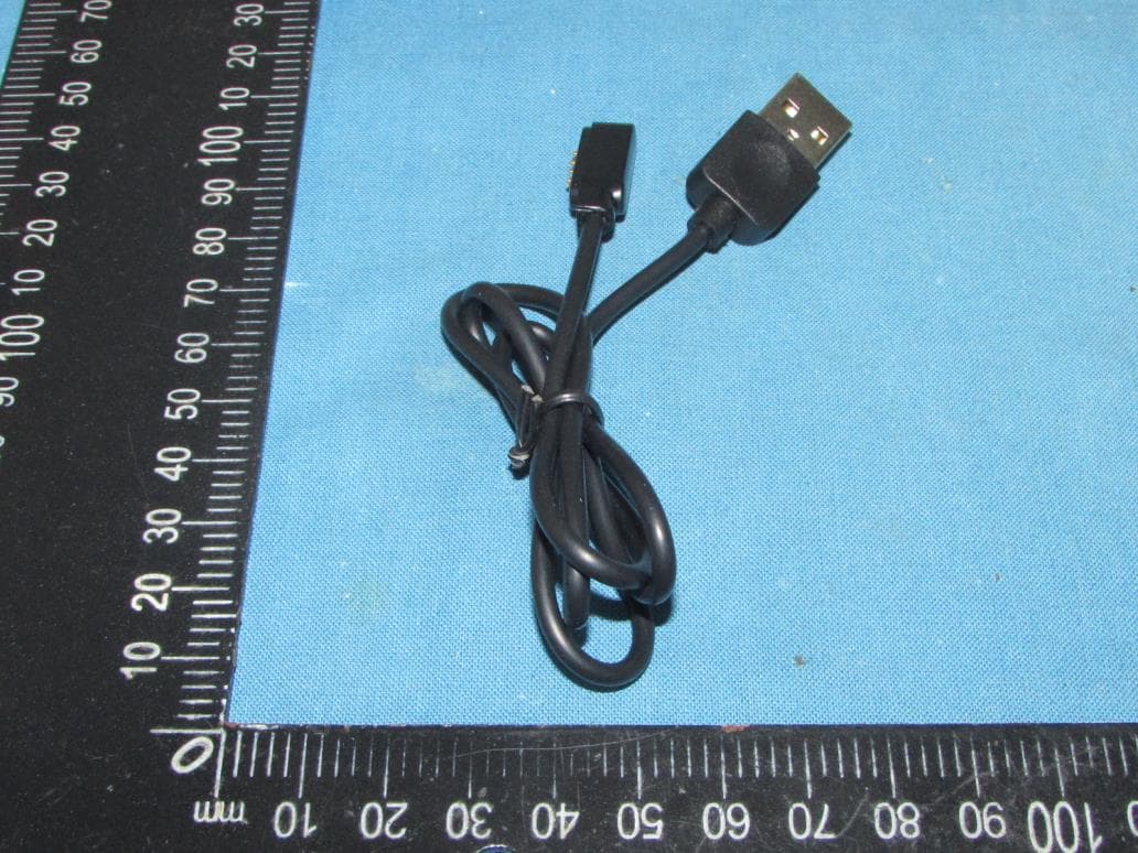
Click to zoom
Application Details
- Equipment Class
- DSS - Part 15 Spread Spectrum Transmitter
- Date of Grant
- Dec 15, 2022
- Application Purpose
- Original Equipment
- Date of Application
- Dec 15, 2022
- Equipment Note
- Bone conduction headphone
- Frequency Range
- 2402.00000000 - 2480.00000000
- Country
- China
Documents & Files
Document Text
Text extracted from the exhibit documents filed with the FCC. Open a document above to read the original.
Users Manual
N/A 1 1 N/A N/A N/A N/A Warranty period: 12 months from the date of purchase Free of charge service: During the warranty period, if there is any breakdown caused by the product's build quality please contact the seller and provide this warranty card together with the sales invoice.The product will be repaired or replaced by a new one. The warranty does not apply under the following circumstances: 1、The product label is broken. 2、Damage caused due to the product being disassembled by a non-authorized repair agent. 3、Damage caused by external force or when there is visible deformation of any of the external parts. 4、The product has been improperly used or stored. 5、Damage or breakdown caused by force majeure. 6、Other situations similar to the above. Customer service information: Customer Name Customer Phone Customer Address Model Number Purchase Date Dealer Invoice number Connect the original charging cable to the magnetic suction port of the headset and the charging head respectively, and the headphone will be fully charged within 2 hours. In order to better ensure the charging life, please use the 5V-1A charging head. To charge the headphone There are positive and negative poles corresponding to the magnetic suction charging. Mutual adsorption can charge normally; Mutual exclusion can not charge, which may cause short circuit of the main board circuit. Please do not force the magnetic suction to fit and contact. Note: The life of rechargeable battery of this product is not shorter than the service life of the product. The battery must be taken out by professional recycling equipment. Any attempt to take out or replace the battery may damage the headphone and affect your warranty rights. Please do not put the battery into the fire to avoid explosion. Warning: Multi-Function Button ( ) Warranty card Power on Power off Pairing Multi-Point Connection Play〡Pause Reject call Accept call End call Voice assistant Accept incoming call and end current one Low latency ON/OFF "Power on" "Power off " "Pairing" Speech N/A N/A N/A N/A Beep Tone Tone K eep p ressing key for 2s Keep pressing key for 3s Keep pressing key for 5s 1.Keep pressing key for 5s 2.Connect device A 3.Turn off Bluetooth of device A 4.Keep pressing key for 5s 5.Connect device B 6.Activate Bluetooth of device A Press once when music playing Press for 1s when incoming call Press once when incoming call Press once during a call Press thrice in standby mode Press for 2s Press four times in During Bluetooth standby mode Bone Conduction Headphone ES-99 8 Plus Bluetooth® V5.3 SIlica gel+Titanium alloy+PC A2DP,AVRCP,HFP More than 10 meters without obstruction 20Hz-20kHz SBC/AAC 8GB MP3/FLAC/WAV/APE/M4A/AAC 180mA / 3.7V li-polymer )emuloV %07( srh 6 2 hrs 5v Bone Conduction speaker 87dB±3dB -38dB±2dB IPX7 32g(1.12oz) Product type Model no# Bluetooth version Material Bluetooth protocols Effective range Frequency response Audio Code Memory capacity Supports audio formats Battery capacity Standby duration Charge time Input voltage Speaker type Speaker sensitivity Microphone sensitivity Waterproof rating Weight 7.Do not use the headphone in extreme light, temperature or vibration. 8.Please do not use headphone in high temperature environment. For example, use a hair dryer and enter the sauna room at the same time or near the stove. 9. Do not place the headphone on an unstable or indined surface. 10. Children should use this device under the supervision of adults. This product is not a toy. Improper use of the headphone may cause injury to itself or may endanger personal and property safety. In case of personal and property damage caused by improper use or warning by consumers in violation of product instructions. the company will not bear all consequences and the company will not bear any legal liability. Reminder 1. The earphone should be stored in a cool and dry place, and the working temperature should be 0一45 °C (32 - 113 F): Working in an envi ronment that is too cold, too hot or too humid may shorten the life of the headphone. 2. Listening to music at too high a volume may damage your hearing and the sound may be distorted. For traffic safety, Please do not use the headphone while driving or riding. 3. After exercise, please wipe the water on the surface of the h eadphone, especially the position of the magnetic charging port, to prevent sweat and salt from eroding the charging port and affecting the service life of the product. 4. Clean the headphones with a soft, dry cloth. 5. Please keep away from sharp and hard objects, which may dama ge the headphone. 6.Do not use the headphone in direct sunlight for a long time. Tips and Maintenance Turn off the headset, connect the PC and ES-868 Plus headphone with the magnetic suction cable provided, and the PC will prompt the removable disk selection window. Select the corresponding folder and copy files to each other. Switch the headphone to the local playback mode to play music in the U flash disk. To download songs: During uploading or downloading data files, do not unplug the USB cable to avoid damage to the headset. Warning: Bluetooth / Memory Press twice in standby mode Voice Reset playback switech
Cover Letter(s)
Sincerely, Name/Title: Wang Zheng Company: Shenzhen XinShuoYa Electronics Co., Ltd. Address: (3F, Area A) Plant 1, Zone B, Dong Wangyang Industrial park Huangtian, Xixiang, Baoan, Shenzhen, China Phone: +86-755-29412609 Fax: / E-Mail: [email protected]
External Photos
Shenzhen Tongzhou Testing Co.,Ltd FCC ID: 2AP5R-ES-998 This report shall not be reproduced except in full, without the written approval of Shenzhen Tongzhou Testing Co.,Ltd Page 1 of 4 EXTERIOR PHOTOGRAPHS OF EUT Fig.1 Fig.2 Shenzhen Tongzhou Testing Co.,Ltd FCC ID: 2AP5R-ES-998 This report shall not be reproduced except in full, without the written approval of Shenzhen Tongzhou Testing Co.,Ltd Page 2 of 4 Fig.3 Fig.4 Shenzhen Tongzhou Testing Co.,Ltd FCC ID: 2AP5R-ES-998 This report shall not be reproduced except in full, without the written approval of Shenzhen Tongzhou Testing Co.,Ltd Page 3 of 4 Fig.5 Fig.6 Shenzhen Tongzhou Testing Co.,Ltd FCC ID: 2AP5R-ES-998 This report shall not be reproduced except in full, without the written approval of Shenzhen Tongzhou Testing Co.,Ltd Page 4 of 4 Fig.7
ID Label/Location Info
Label Location: FCC ID: 2AP5R-ES-998
Internal Photos
Shenzhen Tongzhou Testing Co.,Ltd FCC ID:2AP5R-ES-998 This report shall not be reproduced except in full, without the written approval of Shenzhen Tongzhou Testing Co.,Ltd Page 1 of 3 INTERIOR PHOTOGRAPHS OF EUT Fig.1 Fig.2 Shenzhen Tongzhou Testing Co.,Ltd FCC ID:2AP5R-ES-998 This report shall not be reproduced except in full, without the written approval of Shenzhen Tongzhou Testing Co.,Ltd Page 2 of 3 Fig.3 Fig.4 Bluetooth Antenna Shenzhen Tongzhou Testing Co.,Ltd FCC ID:2AP5R-ES-998 This report shall not be reproduced except in full, without the written approval of Shenzhen Tongzhou Testing Co.,Ltd Page 3 of 3 Fig.5 Fig.6
RF Exposure Info
Shenzhen Tongzhou Testing Co.,Ltd FCC ID: 2AP5R-ES-998 This report shall not be reproduced except in full, without the written approval of Shenzhen Tongzhou Testing Co.,Ltd Page 1 of 3 RADIO FREQUENCY EXPOSURE Limit According to section B.4 of 447498 D04 Interim General RF Exposure Guidance v01 SAR-based thresholds are derived based on frequency, power, and separation distance of the RF source. The formula defines the thresholds in general for either available maximum time-averaged power or maximum time-averaged ERP, whichever is greater. If the ERP of a device is not easily determined, such as for a portable device with a small form factor, the applicant may use the available maximum time-averaged power exclusively if the device antenna or radiating structure does not exceed an electrical length of λ/4. As for devices with antennas of length greater than λ/4 where the gain is not well defined, but always less than that of a half-wave dipole (length λ/2), the available maximum time-averaged power generated by the device may be used in place of the maximum time-averaged ERP, where that value is not known. The separation distance is the smallest distance from any part of the antenna or radiating structure for all persons, during operation at the applicable ERP. In the case of mobile or portable devices, the separation distance is from the outer housing of the device where it is closest to the antenna. The SAR-based exemption formula of § 1.1307(b)(3)(i)(B), repeated here as Formula (B.2), applies for single fixed, mobile, and portable RF sources with available maximum time-averaged power or effective radiated power (ERP), whichever is greater, of less than or equal to the threshold Pth (mW). This method shall only be used at separation distances from 0.5 cm to 40 cm and at frequencies from 0.3 GHz to 6 GHz (inclusive). Pth is given by Formula (B.2). Where and f is in GHz, d is the separation distance (cm), and ERP 20cm is per Formula (B.1). Shenzhen Tongzhou Testing Co.,Ltd FCC ID: 2AP5R-ES-998 This report shall not be reproduced except in full, without the written approval of Shenzhen Tongzhou Testing Co.,Ltd Page 2 of 3 The example values shown in Table B.2 are for illustration only. Frequency (MHz) Distance (mm) 5 10 15 20 25 30 35 40 45 50 300 39 65 88 110 129 148 166 184 201 217 450 22 44 67 89 112 135 158 180 203 226 835 9 25 44 66 90 116 145 175 207 240 1900 3 12 26 44 66 92 122 157 195 236 2450 3 10 22 38 59 83 111 143 179 219 3600 2 8 18 32 49 71 96 125 158 195 5800 1 6 14 25 40 58 80 106 136 169 Shenzhen Tongzhou Testing Co.,Ltd FCC ID: 2AP5R-ES-998 This report shall not be reproduced except in full, without the written approval of Shenzhen Tongzhou Testing Co.,Ltd Page 3 of 3 Conducted Power Results Test Mode Channel Frequency (MHz) Measured Peak Output Power (dBm) GFSK 00 2402 1.48 39 2441 1.3 78 2480 1.27 π/4-DQPSK 00 2402 0.93 39 2441 1.01 78 2480 0.9 Manufacturing tolerance GFSK (Peak) Channel Channel 0 Channel 39 Channel 78 Target (dBm) 1.0 1.0 1.0 Tolerance ±(dB) 1.0 1.0 1.0 π/4-DQPSK (Peak) Channel Channel 0 Channel 39 Channel 78 Target (dBm) 0.5 1.0 0.5 Tolerance ±(dB) 1.0 1.0 1.0 Results Test Mode Channel Frequency (MHz) Max. Tune Up Power (dBm, Peak) Max. Eirp including Tune Up (dBm, Peak) Max. Eirp including Tune Up (mW, Peak) Exemption Limit (mW) GFSK 2402 2.0 3.75 2.37 3 2441 2.0 3.75 2.37 3 2480 2.0 3.75 2.37 3 π/4-DQPSK 2402 1.5 3.25 2.11 3 2441 2.0 3.75 2.37 3 2480 1.5 3.25 2.11 3 The antenna gain of the EUT for BT is 1.75dBi(Max). the Maximum Eirp is used for Routine Evaluation Exemption according to B.4 of 447498 D04 Interim General RF Exposure Guidance v01. So, the SAR evaluation is not required.
Test Report
SPECIFICATION FOR APPROVAL CUSTOMER CUSTOMERS P/N PART NUMBER WAN3216F245H08 DESCRIPTION Chip Antenna 3216 L Ant 2.45G Type H08 VERSION V1.6 ISSUE DATE 2022/01/05 : : 2/11 ONEWAVE TECHNOLOGY CO., LTD. 3216 Chip antenna For Bluetooth / WLAN Applications P/N: WAN3216F245H08 3/11 ONEWAVE TECHNOLOGY CO., LTD. Part Number Information B C D E F Specification 4/11 ONEWAVE TECHNOLOGY CO., LTD. Evaluation Board Dimension 2 nd Evaluation Board Dimension Suggested Matching Circuit ±0.1~0.3nH±0.1pF 5/11 ONEWAVE TECHNOLOGY CO., LTD. 2 nd Layout Dimensions in Clearance area ( Size=8.0*3.0mm) 6/11 ONEWAVE TECHNOLOGY CO., LTD. 7/11 ONEWAVE TECHNOLOGY CO., LTD. 8/11 ONEWAVE TECHNOLOGY CO., LTD. 4.Reliability and Test Condictions ITEM REQUIREMENTS TEST CONDITION Solderability 1. Wetting shall exceed 90% coverage 2. No visible mechanical damage Solder heat Resistance 1. No visible mechanical damage 2. Central Freq. change :within ± 6% Component Adhesion (Push test) 1. No visible mechanical damage The device should be reflow soldered(2305 for 10sec.) to a tinned copper substrate A dynometer force gauge should be applied the side of the component. The device must with-ST-F 0.5 Kg without failure of the termination attached to component. Component Adhesion (Pull test) 1. No visible mechanical damage Insert 10cm wire into the remaining open eye bend ,the ends of even wire lengths upward and wind together. Terminal shall not be remarkably damaged. Thermal shock 1. No visible mechanical damage 2. Central Freq. change :within ±6% Phase Temperature() Time(min) 1 +110±5 30±3 2 Room Temperature Within 3sec 3 -40±2 30±3 4 Room Temperature Within 3sec +110=>30±3min -40=>30±3min Test cycle:10 cycles The chip shall be stabilized at normal condition for 2~3 hours before measuring. Resistance to High Temperature 1. No visible mechanical damage 2. Central Freq. change :within ±6% 3. No disconnection or short circuit. Temperature: +110±5 Duration: 100012hrs The chip shall be stabilized at normal condition for 2~3 hours before measuring. Resistance to Low Temperature 1. No visible mechanical damage 2. Central Freq. change :within ±6% 3. No disconnection or short circuit. Temperature:-40±5 Duration: 100012hrs The chip shall be stabilized at normal condition for 2~3 hours before measuring. Humidity 1. No visible mechanical damage 2. Central Freq. change :within ±6% 3. No disconnection or short circuit. Temperature: 40±2 Humidity: 90% to 95% RH Duration: 100012hrs The chip shall be stabilized at normal condition for 2~3 hours before measuring. 41 sec. 60sec TEMP () 150 230 9/11 ONEWAVE TECHNOLOGY CO., LTD. 5.Soldering and Mounting Mildly activated rosin fluxes are preferred. The minimum amount of solder can lead to damage from the stresses caused by the difference in coefficients of expansion between solder, chip and substrate. The terminations are suitable for all wave and re-flow soldering systems. If hand soldering cannot be avoided, the preferred technique is the utilization of hot air soldering tools. Recommended temperature profiles for re-flow soldering in Figure 1. Products attachment with a soldering iron is discouraged due to the inherent process control limitations. In the event that a soldering iron must be employed the following precautions are recommended. Preheat circuit and products to 150 Never contact the ceramic with the iron tip Use a 20 watt soldering iron with tip diameter of 1.0mm 280 tip temperature (max) 1.0mm tip diameter (max) Limit soldering time to 3 sec. 10/11 ONEWAVE TECHNOLOGY CO., LTD. 6.Packaging Information Tape Specification: Reel Specification: (7, 180 mm) 11/11 ONEWAVE TECHNOLOGY CO., LTD. 7.Storage and Transportation Information Storage Conditions To maintain the solderability of terminal electrodes: 1. Temperature and humidity conditions: -10~ 40 and 30~70% RH. 2. Recommended products should be used within 6 months from the time of delivery. 3. The packaging material should be kept where no chlorine or sulfur exists in the air. Transportation Conditions 1. Products should be handled with care to avoid damage or contamination from perspiration and skin oils. 2. The use of tweezers or vacuum pick up is strongly recommended for individual components. 3. Bulk handling should ensure that abrasion and mechanical shock are minimized.
Test Report
Shenzhen Tongzhou Testing Co.,Ltd FCC ID: 2AP5R-ES-998 Report No.: TZ221103802-E Page 1 of 34 Appendix Test Data for BT(BDR/EDR) (Conducted Measurement) Product Name: Bone conduction headphone Trade Mark: MoreinTech Test Model: ES-998 Plus FCC ID: 2AP5R-ES-998 Environmental Conditions Temperature: 22.8 C Relative Humidity: 56% ATM Pressure: 100.0 kPa Test Engineer: Anna Hu Supervised by: Hugo Chen NOTE N/A Appendix A: 20dB Emission Bandwidth Test Result TestMode Antenna Channel 20db EBW[MHz] FL[MHz] FH[MHz] Limit[MHz] Verdict DH5 Ant1 2402 0.942 2401.574 2402.516 --- --- 2441 0.945 2440.571 2441.516 --- --- 2480 0.948 2479.568 2480.516 --- --- 2DH5 Ant1 2402 1.263 2401.403 2402.666 --- --- 2441 1.305 2440.385 2441.690 --- --- 2480 1.317 2479.382 2480.699 --- --- Shenzhen Tongzhou Testing Co.,Ltd FCC ID: 2AP5R-ES-998 Report No.: TZ221103802-E Page 2 of 34 Test Graphs DH5_Ant1_2402 DH5_Ant1_2441 DH5_Ant1_2480 2DH5_Ant1_2402 Shenzhen Tongzhou Testing Co.,Ltd FCC ID: 2AP5R-ES-998 Report No.: TZ221103802-E Page 3 of 34 2DH5_Ant1_2441 2DH5_Ant1_2480 Shenzhen Tongzhou Testing Co.,Ltd FCC ID: 2AP5R-ES-998 Report No.: TZ221103802-E Page 4 of 34 Appendix B: Occupied Channel Bandwidth Test Result TestMode Antenna Channel OCB [MHz] FL[MHz] FH[MHz] Limit[MHz] Verdict DH5 Ant1 2402 0.88027 2401.5919 2402.4721 --- --- 2441 0.88031 2440.5878 2441.4681 --- --- 2480 0.87209 2479.5962 2480.4683 --- --- 2DH5 Ant1 2402 1.1837 2401.4450 2402.6287 --- --- 2441 1.1830 2440.4477 2441.6307 --- --- 2480 1.1864 2479.4463 2480.6327 --- --- Shenzhen Tongzhou Testing Co.,Ltd FCC ID: 2AP5R-ES-998 Report No.: TZ221103802-E Page 5 of 34 Test Graphs DH5_Ant1_2402 DH5_Ant1_2441 DH5_Ant1_2480 2DH5_Ant1_2402 Shenzhen Tongzhou Testing Co.,Ltd FCC ID: 2AP5R-ES-998 Report No.: TZ221103802-E Page 6 of 34 2DH5_Ant1_2441 2DH5_Ant1_2480 Shenzhen Tongzhou Testing Co.,Ltd FCC ID: 2AP5R-ES-998 Report No.: TZ221103802-E Page 7 of 34 Appendix C: Maximum Peak conducted output power Test Result TestMode Antenna Channel Result[dBm] Limit[dBm] Verdict DH5 Ant1 2402 1.48 ≤30 PASS 2441 1.3 ≤30 PASS 2480 1.27 ≤30 PASS 2DH5 Ant1 2402 0.93 ≤20.97 PASS 2441 1.01 ≤20.97 PASS 2480 0.9 ≤20.97 PASS Shenzhen Tongzhou Testing Co.,Ltd FCC ID: 2AP5R-ES-998 Report No.: TZ221103802-E Page 8 of 34 Test Graphs DH5_Ant1_2402 DH5_Ant1_2441 DH5_Ant1_2480 Shenzhen Tongzhou Testing Co.,Ltd FCC ID: 2AP5R-ES-998 Report No.: TZ221103802-E Page 9 of 34 2DH5_Ant1_2402 2DH5_Ant1_2441 2DH5_Ant1_2480 Shenzhen Tongzhou Testing Co.,Ltd FCC ID: 2AP5R-ES-998 Report No.: TZ221103802-E Page 10 of 34 Appendix D: Carrier frequency separation Test Result TestMode Antenna Channel Result[MHz] Limit[MHz] Verdict DH5 Ant1 Hop 0.844 ≥0.632 PASS 2DH5 Ant1 Hop 1 ≥0.878 PASS Shenzhen Tongzhou Testing Co.,Ltd FCC ID: 2AP5R-ES-998 Report No.: TZ221103802-E Page 11 of 34 Test Graphs DH5_Ant1_Hop 2DH5_Ant1_Hop Shenzhen Tongzhou Testing Co.,Ltd FCC ID: 2AP5R-ES-998 Report No.: TZ221103802-E Page 12 of 34 Appendix E: Time of occupancy Test Result TestMode Antenna Channel BurstWidth [ms] TotalHops [Num] Result[s] Limit[s] Verdict DH5 Ant1 Hop 2.885 110 0.317 ≤0.4 PASS 2DH5 Ant1 Hop 2.891 100 0.289 ≤0.4 PASS Shenzhen Tongzhou Testing Co.,Ltd FCC ID: 2AP5R-ES-998 Report No.: TZ221103802-E Page 13 of 34 Test Graphs DH5_Ant1_Hop 2DH5_Ant1_Hop Shenzhen Tongzhou Testing Co.,Ltd FCC ID: 2AP5R-ES-998 Report No.: TZ221103802-E Page 14 of 34 Shenzhen Tongzhou Testing Co.,Ltd FCC ID: 2AP5R-ES-998 Report No.: TZ221103802-E Page 15 of 34 Appendix F: Number of hopping channels Test Result TestMode Antenna Channel Result[Num] Limit[Num] Verdict DH5 Ant1 Hop 79 ≥15 PASS 2DH5 Ant1 Hop 79 ≥15 PASS Shenzhen Tongzhou Testing Co.,Ltd FCC ID: 2AP5R-ES-998 Report No.: TZ221103802-E Page 16 of 34 Test Graphs DH5_Ant1_Hop 2DH5_Ant1_Hop Shenzhen Tongzhou Testing Co.,Ltd FCC ID: 2AP5R-ES-998 Report No.: TZ221103802-E Page 17 of 34 Appendix G: Band edge measurements Test Result TestMode Antenna ChName Channel RefLevel [dBm] Result [dBm] Limit [dBm] Verdict DH5 Ant1 Low 2402 1.00 -47 ≤-19 PASS High 2480 0.66 -49.56 ≤-19.34 PASS Low Hop_2402 -1.00 -49.65 ≤-21 PASS High Hop_2480 -0.10 -49.21 ≤-20.1 PASS 2DH5 Ant1 Low 2402 -2.08 -50.19 ≤-22.08 PASS High 2480 -0.21 -49.32 ≤-20.21 PASS Low Hop_2402 -3.10 -50.45 ≤-23.1 PASS High Hop_2480 -0.30 -49.28 ≤-20.3 PASS Shenzhen Tongzhou Testing Co.,Ltd FCC ID: 2AP5R-ES-998 Report No.: TZ221103802-E Page 18 of 34 Test Graphs DH5_Ant1_Low_2402 DH5_Ant1_High_2480 DH5_Ant1_Low_Hop_2402 DH5_Ant1_High_Hop_2480 Shenzhen Tongzhou Testing Co.,Ltd FCC ID: 2AP5R-ES-998 Report No.: TZ221103802-E Page 19 of 34 2DH5_Ant1_Low_2402 2DH5_Ant1_High_2480 2DH5_Ant1_Low_Hop_2402 Shenzhen Tongzhou Testing Co.,Ltd FCC ID: 2AP5R-ES-998 Report No.: TZ221103802-E Page 20 of 34 2DH5_Ant1_High_Hop_2480 Shenzhen Tongzhou Testing Co.,Ltd FCC ID: 2AP5R-ES-998 Report No.: TZ221103802-E Page 21 of 34 Appendix H: Conducted Spurious Emission Test Result TestMode Antenna Channel FreqRange [MHz] RefLevel [dBm] Result [dBm] Limit [dBm] Verdict DH5 Ant1 2402 Reference 0.47 0.47 --- PASS 30~1000 0.47 -56.76 ≤-19.53 PASS 1000~26500 0.47 -48.98 ≤-19.53 PASS 2441 Reference 0.46 0.46 --- PASS 30~1000 0.46 -60.94 ≤-19.54 PASS 1000~26500 0.46 -47.74 ≤-19.54 PASS 2480 Reference 0.13 0.13 --- PASS 30~1000 0.13 -58.37 ≤-19.87 PASS 1000~26500 0.13 -47.21 ≤-19.87 PASS 2DH5 Ant1 2402 Reference -0.40 -0.40 --- PASS 30~1000 -0.40 -62.07 ≤-20.4 PASS 1000~26500 -0.40 -50.74 ≤-20.4 PASS 2441 Reference -1.11 -1.11 --- PASS 30~1000 -1.11 -61.52 ≤-21.11 PASS 1000~26500 -1.11 -49.79 ≤-21.11 PASS 2480 Reference -1.79 -1.79 --- PASS 30~1000 -1.79 -60.98 ≤-21.79 PASS 1000~26500 -1.79 -48.5 ≤-21.79 PASS Shenzhen Tongzhou Testing Co.,Ltd FCC ID: 2AP5R-ES-998 Report No.: TZ221103802-E Page 22 of 34 Test Graphs DH5_Ant1_2402_0~Reference DH5_Ant1_2402_30~1000 DH5_Ant1_2402_1000~26500 DH5_Ant1_2441_0~Reference Shenzhen Tongzhou Testing Co.,Ltd FCC ID: 2AP5R-ES-998 Report No.: TZ221103802-E Page 23 of 34 DH5_Ant1_2441_30~1000 DH5_Ant1_2441_1000~26500 DH5…
Text truncated - open the document above for the full version.
Test Report
Report No.: TZ221103802-E Page 1 of 38 FCC TEST REPORT Test report On Behalf of Shenzhen XinShuoYa Electronics Co., Ltd. For Bone conduction headphone Model No: ES-998 Plus, ES-998 Pro, ES-968 Plus, ES-968 Pro, ES-988 Plus, ES-988 Pro, ES-950 Plus, ES-950 Pro, ES-918 Plus, ES-918 Pro, ES-938 Plus, ES-938 Pro, ES-958 Plus, ES-958 Pro FCC ID: 2AP5R-ES-998 Prepared for : Shenzhen XinShuoYa Electronics Co., Ltd. (3F, Area A) Plant 1, Zone B, Dong Wangyang Industrial park Huangtian, Xixiang, Baoan, Shenzhen, China Prepared By : Shenzhen Tongzhou Testing Co.,Ltd 1th Floor, Building 1, Haomai High-tech Park, Huating Road 387, Dalang Street, Longhua, Shenzhen, China Date of Test: 2022/11/14 – 2022/11/28 Date of Report: 2022/11/29 Report Number: TZ221103802-E The test report apply only to the specific sample(s) tested under stated test conditions It is not permitted to copy extracts of these test result without the written permission of the test laboratory. Report No.: TZ221103802-E Page 2 of 38 TEST RESULT CERTIFICATION Applicant’s name ................. : Shenzhen XinShuoYa Electronics Co., Ltd. Address .................................. : (3F, Area A) Plant 1, Zone B, Dong Wangyang Industrial park Huangtian, Xixiang, Baoan, Shenzhen, China Manufacture's Name ............ : Shenzhen XinShuoYa Electronics Co., Ltd. Address .................................. : (3F, Area A) Plant 1, Zone B, Dong Wangyang Industrial park Huangtian, Xixiang, Baoan, Shenzhen, China Product description Trade Mark ............................. : MoreinTech Product name ........................... : Bone conduction headphone Model No ................................ : ES-998 Plus, ES-998 Pro, ES-968 Plus, ES-968 Pro, ES-988 Plus, ES-988 Pro, ES-950 Plus, ES-950 Pro, ES-918 Plus, ES-918 Pro, ES-938 Plus, ES-938 Pro, ES-958 Plus, ES-958 Pro Standards ............................. : FCC Rules and Regulations Part 15 Subpart C Section 15.247 ANSI C63.10: 2013 This publication may be reproduced in whole or in part for non-commercial purposes as long as the Shenzhen Tongzhou Testing Co.,Ltd is acknowledged as copyright owner and source of the material. Shenzhen Tongzhou Testing Co.,Ltd takes no responsibility for and will not assume liability for damages resulting from the reader's interpretation of the reproduced material due to its placement and context. Date of Test ............................. ........... : Date (s) of performance of tests ........... : 2022/11/14-2022/11/28 Date of Issue ......................................... : 2022/11/29 Test Result ............................................ : PASS Testing Engineer : (Nancy Li) Technical Manager : (Hugo Chen) Authorized Signatory : (Andy Zhang) Report No.: TZ221103802-E Page 3 of 38 Revision History Revision Issue Date Revisions Revised By 00 2022/11/29 Initial Issue Andy Zhang Report No.: TZ221103802-E Page 4 of 38 TABLE OF CONTENTS Description Page 1. GENERAL INFORMATION ................................................................................................................ 5 1.1. Description of Device (EUT) ................................................................................................................... 5 1.2 Support equipment List ................................................................................................................................ 5 1.3 EUT configuration ......................................................................................................................................... 5 The following peripheral devices and interface cables were connected during the measurement: ....... 5 1.4 External I/O Cable ........................................................................................................................................ 5 1.5 Description of Test Facility .......................................................................................................................... 6 1.6 Statement of the Measurement Uncertainty ............................................................................................. 7 1.7 Measurement Uncertainty ........................................................................................................................... 7 1.8 Description of Test Modes .......................................................................................................................... 7 2. TEST METHODOLOGY ...................................................................................................................... 8 2.1 EUT Configuration ........................................................................................................................................ 8 2.2 EUT Exercise ................................................................................................................................................ 8 2.3 General Test Procedures ............................................................................................................................ 8 2.4. Test Sample ................................................................................................................................................. 8 3. SYSTEM TEST CONFIGURATION .................................................................................................. 9 3.1 Justification .................................................................................................................................................... 9 3.2 EUT Exercise Software ............................................................................................................................... 9 3.3 Special Accessories ..................................................................................................................................... 9 3.4 Block Diagram/Schematics ......................................................................................................................... 9 3.5 Equipment Modifications .........…
Text truncated - open the document above for the full version.
Test Setup Photos
Shenzhen Tongzhou Testing Co.,Ltd FCC ID: 2AP5R-ES-998 This report shall not be reproduced except in full, without the written approval of Shenzhen Tongzhou Testing Co.,Ltd Page 1 of 2 TEST SETUP PHOTOS OF THE EUT Radiated Emission Below 1GHz Radiated Emission Above 1GHz Shenzhen Tongzhou Testing Co.,Ltd FCC ID: 2AP5R-ES-998 This report shall not be reproduced except in full, without the written approval of Shenzhen Tongzhou Testing Co.,Ltd Page 2 of 2 Conducted Emission
Contact Information
Applicant
Wang Zheng
Test Firm
Shenzhen Tongzhou Testing Co., LTDAndy Zhang
[email protected]+86-755-32902198
Technical Specifications
| # | Rule Parts | Frequency Range | Power Output |
|---|---|---|---|
| 1 | 15C | 2.40 GHz - 2.48 GHz | 1.40 mW |
Other Applications from Shenzhen XinShuoYa Electronics Co., Ltd.
2AP5R-ES-668
Jul 26, 2023Bone conduction headphone
Equipment Class
DSS - Part 15 Spread Spectrum Transmitter