2AP7F-WLSTAGEVEMONIMonitor
TAEHA MECHATRONICS Co., Ltd.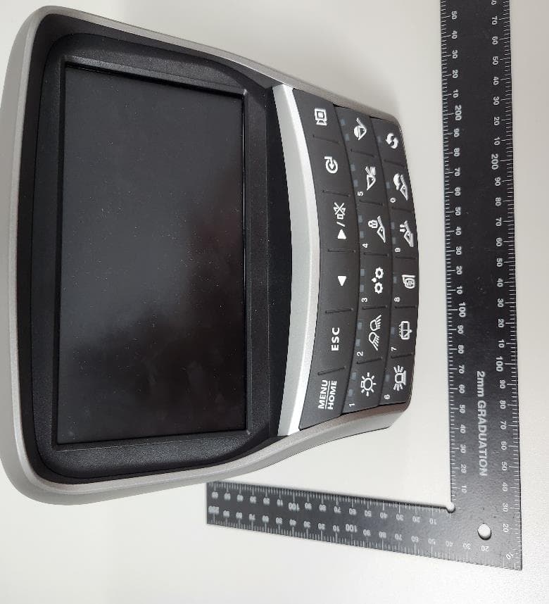
Click to zoom
Application Details
- Equipment Class
- DTS - Digital Transmission System
- Date of Grant
- Sep 21, 2022
- Application Purpose
- Original Equipment
- Date of Application
- Sep 21, 2022
- Equipment Note
- Monitor
- Frequency Range
- 2412.00000000 - 2462.00000000
- Company
- TAEHA MECHATRONICS Co., Ltd.
- Country
- South Korea
Documents & Files
Document Text
Text extracted from the exhibit documents filed with the FCC. Open a document above to read the original.
Users Manual
Wheel Loader MONITOR (7 inch touch screen) Menu bar LCD (touch screen) Switchs Lamps 760F3CD20-1 ·The monitor is adjustable. -Vertical : 30 ̊ -Horizontal : 15 ̊ 1) MAIN DISPLAY ※ You can select or set the menu by the switches or touch screen. ※ selection and change of menu and input value. TYPE A (default) Main menu Press Sub menu 1 6 7 13 10 11 12 8 9 Tap 1 3 4 5 TYPE B 9 8 6 7 10 2 12 11 13 5 4 Main display 2 3 760F3CD11-1 1Clock 2Buzzer 3Wiper speed 4Camera screen 5Menu 11Engine rpm 12Quick menu 1310 lamps 6Machine monitoring 7Fuel rate 8Engine mode/Operation history 9Transmission mode 10ECO gauge 1 ※ In main display, you can move to right side menu by touching each icon. ① Clock setting Set the time (hour, minute and AM or PM) ② Wiper speed Set the wiper speed (slow, normal, fast and very fast) ③ Menu Move to main menu. ④ Buzzer stop If you want to stop buzzer sound, just touch the icon. 2 3 (1) Menu bar 1 4 760F3CD07-1 760F3CD07A-1 ① Clock setting 760F3CD07B-1 ② Wiper speed 760F3CD07C-1 Ⓢ Menu (2) Change display information 1 2 5 3 4 760F3CD08-1 960A3CD08A ① Machine monitoring 760F3CD07E-1 No Buzzer stop ※ In main display, you can check the data and setup what you want by touching each window area or icon. ① Machine monitoring To display the item in main display, select two items of them. ※Priority in the machine monitoring display The priority of the weighing system is the highest. If the weighing system is selected, the other items are not available. To display the other items, the weighing system should not be selected. 2 760F3CD08B-1 ② Fuel rate 760F3CD08C-1 Ⓢ Engine mode 960A3CD08D No Transmission mode ② Fuel rate · Set average fuel rate or a days fuel used on main display screen. ③ Engine mode and operation history ·Set the engine mode (A). ·Set Hour meter / ODO meter (B). 760F3CD08K-1 ④ Transmission mode · Set the clutch cut off (A), shift (B) and torque con- verter lock up mode (C). 760F3CD08L-1 760F3CD08M-1 3 A B A B C (6) Eco gauge ① This gauge indicates the fuel consumption rate and machine load status. So that operators can be careful with fuel economy. ② The fuel consumption rate or machine load is high, the segment is increased. ③ The color of Eco gauge indicates operation status. ·White : Idle operation ·Green : Economy operation ·Yellow : Non-economy operation at a medium level. ·Red : Non-economy operation at a high level. ECO gauge 760F3CD113-1 960A3CD14 960A3CD15 760F3CD16-1 ① If you touch the warning sign (red icon), move to the quick menu. ② You can check the fault message and move the mainte- nance screen by touching relevant area. 960A3CD08J 960A3CD18 (4) Machine monitoring warning ① Warning sign (red icon) will be shown when the tem- p erature of hydraulic oil, cooling water, transmission oil or battery voltage is not normal state. ② Case of warning sign 760F3CD19-1 (5) Communication error ① MCU could not communicate with monitor over 10 sec- onds, error message will be show on the screen. (3) Fault and maintenance warning Icon Description Above 106 ̊C of hydraulic oil temperature Above 105 ̊C of cooling water temperature Above 107 ̊C of transmission oil temperature Below 24.5 voltage of battery (for 3 minutes) Above 100 ̊C of axle oil temperature (option) 4 3) PILOT LAMPS Preheat pilot lamp Fu el warmer pilot lamp Warming up pilot lamp Ride control pilot lamp Float mode pilot lamp Fan reverse pilot lamp Clutch cut off pilot lamp Engine auto shutdown pilot lamp Seat belt pilot lamp T/C lock up pilot lamp 960A3CD90 (1) Warming up pilot lamp ① This lamp lights ON when the coolant temperature is below 30 ̊C (86 ̊F). ② The automatic warming up is cancelled when the engine coolant temperature is above 30 ̊C, or when 10 minutes have passed si nce starting the engine. (2) Seat belt pilot lamp ① This lamp lights ON for the first five seconds after starting the engine. (3) Preheat pilot lamp ① This lamp lights ON when start switch is turned clockwise to the ON position. Light will turn off after approximately 5~45 sec- on ds, depending on engine temperature, indicating that preheat- in g is completed. ② When the lamp goes out the operator should start cranking the e ngine. 5 (4) Engine auto shutdown pilot lamp ① This lamp lights ON when the engine auto shutdown functio n is activated. (5) Clutch cut off pilot lamp ① This lamp lights ON when clutch cut off mode is set L, M, H. (6) Float mode pilot lamp ① This lamp lights ON when the boom float is activated. (7) Ride control pilot lamp (option) Auto ride control ① This lamp lights ON when the automatic ride control function is activated (ON, Conditional speed setting). Manual ride control ① This lamp lights ON when the manual ride control function is activated (ON, Always setting). 6 (8) Fan reverse pilot lamp ① This lamp lights ON when the cooling fan reverse mode is acti- vated (9) Torque converter lock up pilot lamp (option) ① This lamp lights ON when the torque converter lock up function is operating. (10) Fuel warmer pilot lamp ① This lamp is turned ON when the coolant temperature is belo w 10 ̊C (50 ̊F) or the hydraulic oil temperature 20 ̊C (68 ̊F). ② The automatic fuel warming is cancelled when the engine coolant temperature is above 60 ̊C and the hydraulic oil tem- perature is above 45 ̊C since the start switch was ON position. 7 3) SWITCHES Menu/Home switch ESC switch Left/Right switch Enter switch Camera switch Main light switch Beacon lamp switch Work light switch Central grease lubrication switch Rear wiper and washer switch Mirror defrost switch Ride control switch Fin e modulation switch Q uick coupler switch De tent setting switch Work mode switch 760F3CD95-1 ※ If you push left or right switch ( ) on main display, show the select box on current time. Move to next item in order by using left / right button. (① Time → ② Buzzer → ③ Wiper → ④ Camera → ⑤ Menu → ⑥ Machine monitoring → ⑦ Fuel rate → ⑧ Engine mode/Operation history → ⑨ Transmission mode → ⑩ Quick menu) ※ Move to selected setting screen by using …
Text truncated - open the document above for the full version.
Cover Letter(s)
TAEHA MECHATRONICS Co., Ltd. Elproma Elektronika Sp. z o.o Rev 11/20/07 Federal Communications Commission Authorization and Evaluation Division Confidentiality Request regarding application for certification of FCC ID: 2AP7F-WLSTAGEVEMONI Pursuant to Sections 0.457 and 0.459 of the Commission’s Rules, we hereby request confidential treatment of information accompanying this application as outlined below: Exhibit Type File Name Block Diagram WL STAGE-VE Monitor_Blk.pdf Part list WL STAGE-VE Monitor _Plist.pdf Schematics WL STAGE-VE Monitor _Schem.pdf Operational Description WL STAGE-VE Monitor _OpDesc.pdf The above materials contain trade secrets and proprietary information not customarily released to the public. The public disclosure of these materials may be harmful to the applicant and provide unjustified benefits to its competitors. The applicant understands that pursuant to Section 0.457 of the Rules, disclosure of this application and all accompanying documentation will not be made before the date of the Grant for this application. In additional to above mentioned documents, in order to comply with the marketing regulations in Title 47 CFR §2.803 and the importation rules in Title 47 CFR §2.1204, while ensuring that business sensitive information remains confidential until the actual marketing of newly authorized devices, we request Short Term Confidentiality of the following attachment(s); Exhibit Type File Name External Photo WL STAGE-VE Monitor _Ext Photos.pdf Internal Photo WL STAGE-VE Monitor _Int Photos.pdf Manual WL STAGE-VE Monitor _Manual.pdf Test Set-up Photo WL STAGE-VE Monitor _Tsup Photos.pdf For 45 days, pursuant to Public Notice DA 04-1705. OR For 180 days pursuant to KDB 726920 D01. Sincerely, Byoungsun Lee / Junior Research Engineer
Cover Letter(s)
TAEHA MECHATRONICS Co., Ltd. Sept 19, 2022 Timco Engineering, Inc. 849 N.W. State Road 45 P.O. Box 370a Newberry, Florida 32669 USA Letter of Authorization We, the undersigned, hereby authorize In Jung Kim of ICR Co.,Ltd. to act on our behalf in all manners relating to application for equipment authorization for FCC ID : 2AP7F-WLSTAGEVEMONI including signing of all documents relating to these matters. Any and all acts carried out by In Jung Kim of ICR Co.,Ltd. on our behalf shall have the same affect as acts of our own. This authorization is valid until further written notice from TAEHA MECHATRONICS Co., Ltd. “I, the undersigned, hereby certify that we are not subject to a denial of federal benefits, that includes FCC benefits, pursuant to Section 5301 of the Anti-Drug Abuse Act of 1988, 21 U.S.C. 853(a).” Sincerely, Byoungsun Lee / Junior Research Engineer
External Photos
Exterior Photographs Front Top Rear Bottom Side 1 Side 2 Side 3 Side 4 Side port
ID Label/Location Info
Label TAEHA MECHATRONICS Co., Ltd. Model: WL-STAGE VE Monitor FCC ID : 2AP7F-WLSTAGEVEMONI This device complies with Part 15 of the FCC Rules. Operation is subject to the following two conditions: (1) this device may not cause harmful interference, and (2) this device must accept any interference received, including interference that may cause undesired operation
Internal Photos
Interior Photographs Interior Main Board - Front Top Main Board(Open Shield) - Front Top Main board - Rear Bottom Switch Board -Front Top Switch Board - Rear Bottom SMD Antenna
RF Exposure Info
페이지(page) : ( 2 )/( 총(Total) 7 ) ICRT-QPA-17-03 Rev.2 Report No. ICRT-TR-E222376-0A Contents 1. Applicant & Manufacturer & Test Laboratory Information .................................................................................. 4 1.1 Applicant information ........................................................................................................................................ 4 1.2 Manufacturer Information ................................................................................................................................. 4 1.3 Test Laboratory Information ............................................................................................................................ 4 2. Equipment under Test(EUT) Information ................................................................................................................. 5 2.1 General Information ........................................................................................................................................... 5 2.2 Additional Information ...................................................................................................................................... 5 2.3 Mode of operation during the test .................................................................................................................. 5 2.4 Modifications of EUT ......................................................................................................................................... 5 3. Maximum Permissible Exposure ............................................................................................................................... 6 3.1 RF Exposure calculation .................................................................................................................................. 6 3.1 Result ..................................................................................................................................................................... 7 페이지(page) : ( 3 )/( 총(Total) 7 ) ICRT-QPA-17-03 Rev.2 Report No. ICRT-TR-E222376-0A Revision History Issued Report No. Issued Date Revisions Effect Section ICRT-TR-E222376-0A 2022.09.20 Initial Issue All 페이지(page) : ( 4 )/( 총(Total) 7 ) ICRT-QPA-17-03 Rev.2 Report No. ICRT-TR-E222376-0A 1. Applicant & Manufacturer & Test Laboratory Information 1.1 Applicant information Applicant TAEHA MECHATRONICS Co., Ltd. Address 421, Bakdal-ro, Manan-gu, Anyang-si, Gyeonggi-do, Republic of Korea Contact Person Byoungsun Lee Telephone No. +82-31-463-8075 Fax No. +82-31-447-0529 E-mail [email protected] 1.2 Manufacturer Information Manufacturer TAEHA MECHATRONICS Co., Ltd. Address 421, Bakdal-ro, Manan-gu, Anyang-si, Gyeonggi-do, Republic of Korea 1.3 Test Laboratory Information Conducted tests were performed at Laboratory ICR Co., Ltd. Address 112, Hwanggeum 3-ro 7beon-gil, Hagun-ri, Yangchon-eup, Gimpo-si, Gyeonggi- do, Korea Telephone No. +82-2-6351-9002 Fax No. +82-2-6351-9007 RRA No. KR0165 KOLAS No. KT652 페이지(page) : ( 5 )/( 총(Total) 7 ) ICRT-QPA-17-03 Rev.2 Report No. ICRT-TR-E222376-0A 2. Equipment under Test(EUT) Information 2.1 General Information Product Name Monitor Brand Name - Model Name WL-STAGE VE Monitor Additional Model Name - FCC ID 2AP7F-WLSTAGEVEMONI 2.2 Additional Information Equipment Class DTS - Digital Transmission System Device Type Stand-alone Operating Frequency 802.11n(HT20) 2 412 ㎒ ~ 2 462 ㎒ RF Output Power 802.11n(HT20) 14.25 ㏈m Number of Channel 802.11n(HT20) 11 Modulation Type 802.11n(HT20) : OFDM Antenna Type SMD Antenna Antenna Gain 3.5 ㏈i Antenna Operating Mode Single Antenna Equipment with only one antenna 2.3 Mode of operation during the test - The EUT is continuous transmission mode during the test with set at Low Channel, Middle Channel, and High Channel. To get a maximum radiated emission levels from the EUT, the EUT was moved throughout the XY, YZ, XZ planes. 2.4 Modifications of EUT - None 페이지(page) : ( 6 )/( 총(Total) 7 ) ICRT-QPA-17-03 Rev.2 Report No. ICRT-TR-E222376-0A 3. Maximum Permissible Exposure 3.1 RF Exposure calculation According to the FCC rule 1.1310 table 1B, the limit for the maximum permissible RF exposure for an uncontrolled environment are f/1500 ㎽/㎝² for the frequency range between 300 ㎒ and 1 500 ㎒ and 1.0 ㎽/㎝² for the frequency range between 1 500 ㎒ and 100 000 ㎒. The electric field generated for a 1 ㎽/㎝² exposure is calculated as follows: E = √ (30 * P * G) / d, and S = E² / Z = E² / 377, because 1 ㎽/㎝² = 10 W/m² Where S = Power density in ㎽/㎝², Z = Impedance of free space, 377 Ω E = Electric filed strength in V/m, G = Numeric antenna gain, and d = distance in meter Combing equations and rearranging the terms to express the distance as a function of the remaining variable d = √ (30 * P * G) / (377 *10 S) Changing to units of ㎽ and cm, using P (㎽) = P (W) / 1 000, d (㎝) = 0.01 * d (m) d = 0.282 * √ (P * G) / S Where d = distance in ㎝, P = Power in ㎽, G = Numeric antenna gain, and S = Power density in ㎽/㎝² 페이지(page) : ( 7 )/( 총(Total) 7 ) ICRT-QPA-17-03 Rev.2 Report No. ICRT-TR-E222376-0A 3.1 Result According to above equation, the following result was obtained. Operating Mode Target Power W / tolerance Max tune up power Antenna Gain Power Density (㎽/㎝²) @ 20 ㎝ Separation Limit (㎽/㎝²) (㏈m) (㎽) Log Linear 802.11n(HT20) 14.25 ± 1.0 15.25 33.50 3.50 2.24 0.0149 1.00 For getting power density at 20 ㎝ separation in above table, following formula was used. S = P * G / (4π * R²) = 33.50 * 2.24 / (4 * π * 20^2) = 0.014 9 Where: S = Power Density, P = Power input to the external antenna (Output power from the EUT antenna port (㏈m) – cable loss (㏈)), G = Gain of Transmit Antenna (linear gain), R = Distance from Transmitting Antenna - END -
Test Report
Product Specification Serica-SR4W035-PS-1.0 Page 1 Antennas for Wireless M2M Applications 1. Features Antenna for 2.4GHz applications Bluetooth, Wi-Fi, ZigBee, ISM. Maintains high performance on device: DFI (Designed for Integration) Ultra-low profile innovative design. SMD mounting Supplied on Tape and Reel Automotive temperature rating. 2. Description Serica is intended for use with 2.4GHz applications. The antenna only requires a small ground plane. It is ideal for single and MIMO antenna systems. This product specification shows the performance of the antenna over the frequency range 2.4 – 2.5GHz. 3. Applications Wearable devices Medical equipment Tablets Network Devices MIMO Systems IP Cameras Access Points Serica 2.4GHz Antenna Part No. SR4W035 lamiiANT ® Product Specification Serica Part No. SR4W035 Antennas for Wireless M2M Applications Product Specification Serica-SR4W035-PS-1.0 Page 2 4. Part Number Serica: SR4W035 5. General Data 6. RF Characteristics Product name Serica Part Number SR4W035 Frequency 2.4 – 2.5 (GHz) Polarization Linear Operating temperature -40°C to140°C Environmental Condition Test ISO16750-4 5.1.1.1/5.1.2.1/5.3.2 Impedance with matching 50 Ω Weight <1g Antenna type SMD Dimensions 6.0 x 4.0 x 0.4 (mm) 2400 - 2500 MHz Conditions Peak gain 3.50dBi All data measured on Antenova’s evaluation PCB Part No. SR4W035-EVB-1 Average gain (Linear) -1.50dBi Average efficiency >65% Maximum return loss -10.0dB Maximum VSWR 1.85:1 Serica Part No. SR4W035 Antennas for Wireless M2M Applications Product Specification Serica-SR4W035-PS-1.0 Page 3 7. RF Performance 7.1 Return Loss 7.2 VSWR Serica Part No. SR4W035 Antennas for Wireless M2M Applications Product Specification Serica-SR4W035-PS-1.0 Page 4 7.3 Antenna pattern 2400 MHz – 2500 MHz 3D pattern at 2.45 GHz Drag to rotate pattern and PCB by using Adobe Reader (Click to Activate) Serica Part No. SR4W035 Antennas for Wireless M2M Applications Product Specification Serica-SR4W035-PS-1.0 Page 5 8. Antenna Dimensions Bottom Side Dimensions L W H Length Width Height 6.0 ±0.1 4.0 ±0.1 0.4 +0.1 -0.0 All Dimensions in (mm) Serica Part No. SR4W035 Antennas for Wireless M2M Applications Product Specification Serica-SR4W035-PS-1.0 Page 6 10.0 Schematic symbol and Pin definition The circuit symbol for the antenna is shown below. The antenna has 6 pins with only two as functional. All other pins are for mechanical strength. 9.0 Antenna footprint The recommended host PCB footprint is below. 6 copper pads all 1.0 x 1.0 (mm) Pin Description 2 Feed 3,4,6 Return/GND 1,5 Not used (Mechanical only) Serica Schematic Symbol 1 2 3 4 5 6 Serica Part No. SR4W035 Antennas for Wireless M2M Applications Product Specification Serica-SR4W035-PS-1.0 Page 7 11. Electrical Interface 11.1 Transmission Line All transmission lines should be designed to have a characteristic impedance of 50Ω. • The length of the transmission lines should be kept to a minimum. • Any other parts of the RF system like transceivers, power amplifiers, etc, should also be designed to have an impedance of 50 Ω. Once the material for the PCB has been chosen (PCB thickness and dielectric constant), a coplanar transmission line can easily be designed using any of the commercial software packages for transmission line design. For the chosen PCB thickness, copper thickness and substrate dielectric constant, the program will calculate the appropriate transmission line width and gaps on either side of the track, so the characteristic impedance of the co-planar transmission is 50 Ω. 11.2 Matching Circuit The antenna requires a matching circuit that must be optimized for each product. The matching circuit will require up to five components and the following circuit should be designed into the host PCB. Not all components may be required but should be included as a precaution. The matching network must be placed close to the antenna feed to ensure it is more effective in tuning the antenna. Serica Part No. SR4W035 Antennas for Wireless M2M Applications Product Specification Serica-SR4W035-PS-1.0 Page 8 12.0 Antenna Integration Guide 12.1 Antenna Placement Whichever size host PCB is used, the antenna should ideally be placed on the host PCB’s longest edge at the centre. Where the centre is not a viable option, the antenna can be placed offset on the PCB to within the limits shown below. A minimum of 6mm from either PCB edge should be observed. Where possible this distance should be greater than 6mm. Serica Part No. SR4W035 Antennas for Wireless M2M Applications Product Specification Serica-SR4W035-PS-1.0 Page 9 12.2 Host PCB Layout The footprint and clearance of the host PCB must meet the antenna specification. An example of the PCB layout, below, shows the antenna footprint with clearance. Pins 3, 4 and 6 (GND) are shown directly connecting to the GND with the shortest route. The feed (Pin 2) connects to the matching circuit close to the antenna. Example host layout Serica Part No. SR4W035 Antennas for Wireless M2M Applications Product Specification Serica-SR4W035-PS-1.0 Page 10 12.3 Host PCB Clearance The diagram below shows the antenna footprint and clearance through all layers on the PCB. Only the antenna pads and connections to feed and GND are present within this clearance area. The clearance area required is 6.0 x 4.0 (mm). The clear-out area is simply defined as the same size as the antenna. No additional clearance is required. Clearance area Serica Part No. SR4W035 Antennas for Wireless M2M Applications Product Specification Serica-SR4W035-PS-1.0 Page 11 14.0 Reference Board The reference board has been designed for the purpose of evaluating SR4W035 and includes an SMA female connector. SR4W035-EVB-1 Evaluation Board To order a reference board contact [email protected]. Please state if a single antenna or two antenna EVB is required. Serica Part No. SR4W035 Antennas for Wireless M2M Applications Product Specification Serica-SR4W035-PS-1.0 Page 12 14.1 Re…
Text truncated - open the document above for the full version.
Test Report
페이지(page) : ( 2 )/( 총(Total) 25 ) ICRT-QPA-17-03 Rev.2 Report No. ICRT-TR-E222375-0A Contents 1. Applicant & Manufacturer & Test Laboratory Information .................................................................................. 4 1.1 Applicant information ........................................................................................................................................ 4 1.2 Manufacturer Information ................................................................................................................................. 4 1.3 Test Laboratory Information ............................................................................................................................ 4 2. Equipment under Test(EUT) Information ................................................................................................................. 5 2.1 General Information ........................................................................................................................................... 5 2.2 Additional Information ...................................................................................................................................... 5 2.3 Mode of operation during the test .................................................................................................................. 5 2.4 Modifications of EUT ......................................................................................................................................... 5 3. Test Summary ................................................................................................................................................................. 6 3.1 Test standards and results .............................................................................................................................. 6 3.2 Purpose of the test ............................................................................................................................................. 6 3.3 Test Methodology ............................................................................................................................................... 6 3.4 Configuration of Test System ......................................................................................................................... 6 3.5 Antenna requirement ......................................................................................................................................... 7 4. Used equipment on test ............................................................................................................................................... 8 5. 6 ㏈ Bandwidth .............................................................................................................................................................. 9 5.1 Operating environment ..................................................................................................................................... 9 5.2 Measurement method ........................................................................................................................................ 9 5.3 Test data ............................................................................................................................................................... 9 6. Maximum Conducted Output Power ....................................................................................................................... 11 6.1 Operating environment ................................................................................................................................... 11 6.2 Measurement method ...................................................................................................................................... 11 6.3 Test data ............................................................................................................................................................. 11 7. Power Spectral Density .............................................................................................................................................. 12 7.1 Operating environment ................................................................................................................................... 12 7.2 Measurement method ...................................................................................................................................... 12 7.3 Test data ............................................................................................................................................................. 12 8. Conducted Spurious Emission ................................................................................................................................ 14 8.1 Operating environment ................................................................................................................................... 14 8.2 Measurement method ...................................................................................................................................... 14 8.3 Test data ............................................................................................................................................................. 14 9. Radiated Spurious Emission .................................................................................................................................... 19 9.1 Operating environment ................................................................................................................................... 19 9.2 Measurement method ...................................................................................................................................... 19 9.3 Test setup ...........................................................................................................................................…
Text truncated - open the document above for the full version.
Test Setup Photos
페이지(page) : ( 1 )/( 총 2 ) ICRT-QP-22-02 Rev.5 Report No. ICRT-TR-E222375-0A Test Setup Photo Test Setup Radiated measurement for below 1 ㎓ (Front side) Test Setup Radiated measurement for below 1 ㎓ (Rear side) 페이지(page) : ( 2 )/( 총 2 ) ICRT-QP-22-02 Rev.5 Report No. ICRT-TR-E222375-0A Test Setup Radiated measurement for Above 1 ㎓ (Front side) Test Setup Radiated measurement for Above 1 ㎓ (Rear side)
Contact Information
Applicant
Kangil Lee(Principal Research Engineer)
Test Firm
ICR Co., Ltd.Sim Sang-Woo
Technical Specifications
| # | Rule Parts | Frequency Range | Power Output |
|---|---|---|---|
| 1 | 15C | 2.41 GHz - 2.46 GHz | 27.00 mW |
Other Applications from TAEHA MECHATRONICS Co., Ltd.
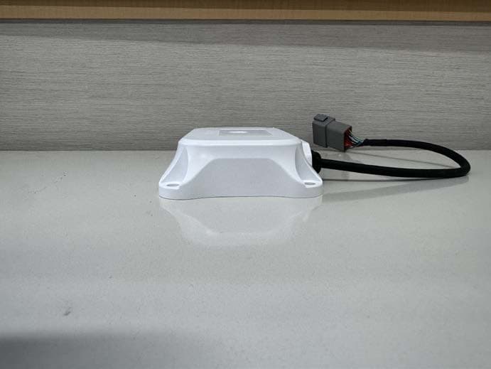
2AP7FRMCUM5
Feb 14, 2024RMCU
Equipment Class
PCB - PCS Licensed Transmitter