2APK7-92219462110Infrared (IR) Bin
Fastenal Company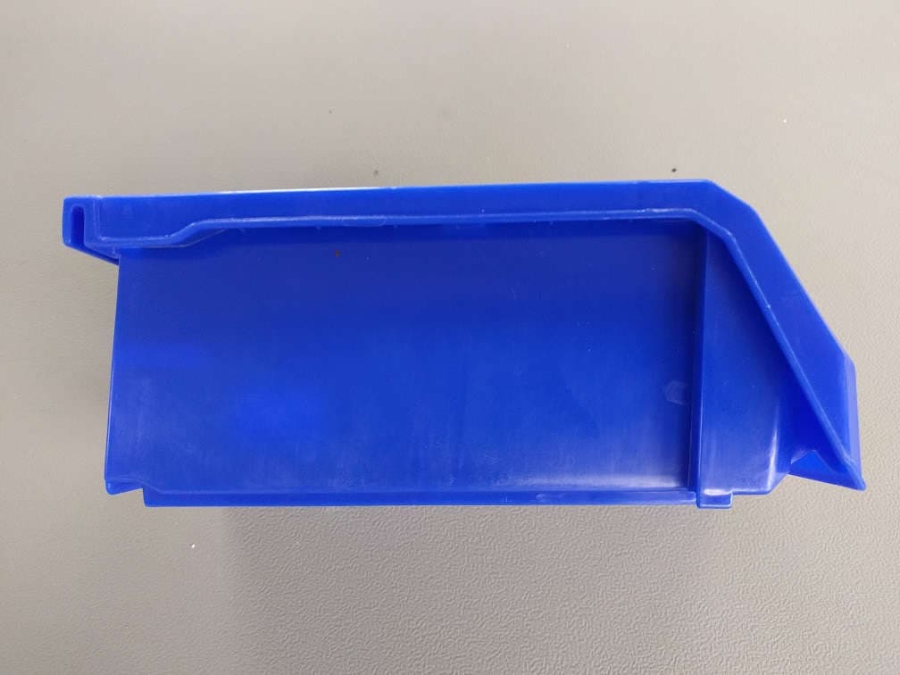
Click to zoom
Application Details
- Equipment Class
- DTS - Digital Transmission System
- Date of Grant
- Jul 31, 2022
- Application Purpose
- Original Equipment
- Date of Application
- Jul 18, 2022
- Equipment Note
- Infrared (IR) Bin
- Frequency Range
- 2402.00000000 - 2480.00000000
- Company
- Fastenal Company
- Country
- United States
Documents & Files
Document Text
Text extracted from the exhibit documents filed with the FCC. Open a document above to read the original.
Users Manual
FAST Bin℠ User Manual © Copyright 2018 Fastenal Company. All rights reserved. FAST Bin℠ User Manual Fastenal Company FAST Bin℠ User Manual Page | 1 Revision 4.0 Trademark Information Fastenal is a registered trademark of Fastenal Company. FAST Bin is a service mark of Fastenal Company. All other trade names mentioned in this manual are the trademarks or registered trademarks of their respective holders. Support Information These units are manufactured, owned, installed, maintained, and operated by: Fastenal Company 2001 Theurer Blvd Winona, Minnesota 55987 USA Support (toll free): +1 866-829-1564 CAUTION: Qualified Fastenal support staff are required to install and maintain the FAST Bin℠ system. Unauthorized installation, changes, or maintenance by non-Fastenal personnel can result in the system not working as intended and could void the user’s authority to operate the equipment. Please contact Fastenal at the toll-free number listed above if you need assistance or have questions regarding the FAST Bin system. FAST Bin℠ User Manual Fastenal Company FAST Bin℠ User Manual Page | 2 Revision 4.0 System Description This document describes the Fastenal® FAST Bin℠ system, which enables remote monitoring of inventory by means of sensing and communication technologies to report the state of the inventory to a central Fastenal server. The FAST Bin system consists of the five devices that are used to create two different types of installations: Infrared (IR) Bins and Radio Frequency Identification (RFID) Bins. The devices include IR Bins, RFID Bins, Controllers, Readers, and Repeaters. The IR system uses IR Bins, Controller(s) and Repeater(s) to communicate information, while the RFID system uses RFID Bins, Controller(s), and a Reader which is enclosed in the RFID enclosure. Each device uses one or more communication technologies to transfer the information, as shown in Figure 1: Figure 1. FAST Bin Communication Technologies The communication technologies are as follows: • Wi-Fi: Standard technology used to connect digital devices to each other and to the Internet • Cellular: A network technology that enables mobile device communication via cells and transceivers FAST Bin℠ User Manual Fastenal Company FAST Bin℠ User Manual Page | 3 Revision 4.0 • Ethernet: A standard technology used to connect digital devices on a network using a wired connection • Long Range Radio (LoRa): A protocol that provides low power, wide area communication between remote sensors and gateways connected to a network • Bluetooth Low Energy (BLE): A power-conserving variant of Bluetooth technology, which provides short-range wireless interconnection of digital devices System Operation The FAST Bin system automates the current manual method of checking inventory that is stored in Fastenal standard Bin systems as shown in Figure 2: Figure 2. Standard Fastenal Bin Systems The following subsections describe how each of the FAST Bin devices work. Infrared (IR) Bins The IR Bins consist of a standard Bin plus two printed circuit boards (PCBs) that sit opposite each other inside the Bin; the PCBs are protected by a plastic insert as shown in Figure 3: Figure 3. Infrared (IR) Bin FAST Bin℠ User Manual Fastenal Company FAST Bin℠ User Manual Page | 4 Revision 4.0 There is an array of LED IR emitters on one PCB and corresponding IR sensors on the opposite PCB. Obstruction of an IR beam equates to the presence of inventory at that point inside the Bin. The obstructed or unobstructed state, as detected by the sensors, is transmitted to the Controller by means of Bluetooth Low Energy (BLE), and the data for each Bin is then transmitted to the Fastenal Server via the Internet. Multiple IR Bins communicate via BLE directly with a single Controller. If distance or obstructions are an issue, a Repeater can be used. In this case, the IR Bins communicate via BLE with the Repeater, which in turn communicates via Long Range Radio (LoRa) with the Controller. Radio Frequency Identification (RFID) Bins RFID Bins are standard Bins with RFID tags applied (as shown in Figure 4). When a Bin has been emptied of its contents, it is manually placed in the replenishment area of the RFID enclosure. The Reader, which is located in the enclosure’s subfloor, registers the presence of the RFID tag on the Bin. The Reader then transmits the tag ID to the Controller via LoRa, and the data is then transmitted to the Fastenal Server via the Internet. A typical RFID enclosure is shown in Figure 5. Figure 4. Bin with Radio Frequency Identification (RFID) tag FAST Bin℠ User Manual Fastenal Company FAST Bin℠ User Manual Page | 5 Revision 4.0 Figure 5. RFID Bins in Standard Rivet Rack Reader The Reader reads Bins with RFID tags and sends the information to the Controller via a LoRa connection. See the Radio Frequency Identification (RFID) Bins section for more information on the location of the Reader. Controller The Controller, which is shown in Figure 6, is a communication hub for the overall FAST Bin system and uses several different data streams to communicate with the other FAST Bin devices. The only concurrent transmissions possible are LoRa with either Ethernet, Wi-Fi, or Cellular communications as the firmware does not allow other interactions. The Controller uses the following technologies to communicate with the other FAST Bin devices: • Wi-Fi • Cellular Modem • Ethernet • LoRa • BLE FAST Bin℠ User Manual Fastenal Company FAST Bin℠ User Manual Page | 6 Revision 4.0 Figure 6. FAST Bin Controller Repeater The Repeater, which is shown Figure 7, is used when it is necessary to increase the range of the BLE transmitters. BLE messages are received by the BLE Module. The Repeater then relays the message delivered to the Controller using LoRa communications. Figure 7. FAST Bin Repeater FAST Bin℠ User Manual Fastenal Company FAST Bin℠ User Manual Page | 7 Revision 4.0 Indicator Lights The following sections define the indicator lights located on each device. For all the dev…
Text truncated - open the document above for the full version.
Cover Letter(s)
TO: Federal Communication Commission Equipment Authorization Division Application Processing Branch 7435 Oakland Mills Rd Columbia, MD 21046 ATTENTION: Federal Communication Commission Equipment Authorization To whom it may concern, We would like to submit for Certification to FCC: [2APK7-92219462110]. Please find in the following application all related documentation to support this New Single Certification. We would appreciate your prompt attention to the submittal. Applicant Company name: Fastenal Contact Name: Tony McIntosh Address: 8918 Beckett Road, West Chester, OH 45069 Telephone No: 513-644-0074 Fax No: Email: [email protected] FCC ID Number: 0027435023 Signature: Date: 5-13-2022 Signed by (printed name): Tony McIntosh
ID Label/Location Info
FCC ID: 2APK7-92219462110 IC: 23979-92219462110 922194621 2001 TheurerBlvd Winona, MN 55987 USA
RF Exposure Info
Engineering Test Report No. 2103912-13 Rev. A Report Date June 30, 2022 Manufacturer Name Fastenal Manufacturer Address 2001 Theurer Blvd Winona, MN 55987 Product Name Brand/Model No. Infrared Bin, Model Nos. IR220, IR230, IR240 Date Received December 7, 2021 Assessment Date June 30, 2022 Specifications FCC 47 CFR Part 2.1093 KDB, 447498 D01 OET Bulletin 65:1997 RSS-102 EN 62311 EN 62479 AS/NZS 2772.2 RSP 3 Test Facility Elite Electronic Engineering, Inc. 1516 Centre Circle, Downers Grove, IL 60515 Signature Tested by Mark E. Longinotti Signature Approved by Raymond J. Klouda, Registered Professional Engineer of Illinois – 44894 PO Number 01N9964-112921-0906 This report is for your exclusive use. Any copying or replication of this report to or for any other person or entity, or use of our name or trademark, is permitted only with our prior written permission. This report sets forth our findings solely with respect to the test samples identified herein. The results set forth in this report are not indicative or representative of the quality or characteristics of the lot from which a test sample was taken or any similar or identical product unless specifically and expressly noted. Our report includes the results thereof based upon the information that you provided to us. You have 60 days from date of issuance of this report to notify us of any material error or omission caused by our negligence, provided, however, that such notice shall be in writing and shall specifically address the issue you wish to raise. A failure to raise such issue within the prescribed time shall constitute your unqualified acceptance of the completeness of this report, the tests conducted and the correctness of the report contents. This report shall not be reproduced, except in full, without the written approval of Elite Electronic Engineering Inc. Engineering Test Report No. 2103912-13 Rev. A This report shall not be reproduced, except in full, without the written approval of Elite Electronic Engineering Inc. Page 2 of 17 Table of Contents 1. Report Revision History ............................................................................................................................ 3 2. Introduction ............................................................................................................................................... 4 3. Subject of Investigation ............................................................................................................................. 4 4. Standards and Requirements ................................................................................................................... 4 5. Sample Calculations ................................................................................................................................. 5 6. Photographs of EUT .................................................................................................................................. 6 7. Limits and Requirements .......................................................................................................................... 8 7.1. Requirements mandated by the FCC ....................................................................................................... 8 7.2. Requirements mandated by Innovation, Science and Economic Development Canada ....................... 10 7.3. Requirements mandated by the European Union and outlined in EN 62311 ......................................... 12 7.4. Requirements mandated by Australia/New Zealand and outlined in AS/NZS 2772.2 ............................ 13 8. Assessment Results ................................................................................................................................ 14 8.1. RF Exposure Evaluation Relevant to the Requirements of the FCC ...................................................... 14 8.2. RF Exposure Evaluation Relevant to the Requirements of the ISED ..................................................... 14 8.3. RF Exposure Evaluation Relevant to the Requirements of the EU ........................................................ 14 8.4. RF Exposure Evaluation Relevant to the Requirements of Australia/New Zealand ............................... 14 8.5. RF Exposure Evaluation Relevant to the Requirements of the FCC ...................................................... 15 8.6. RF Exposure Evaluation Relevant to the Requirements of the ISED ..................................................... 15 8.7. RF Exposure Evaluation Relevant to the Requirements of the EU ........................................................ 15 8.8. RF Exposure Evaluation Relevant to the Requirements of Australia/New Zealand ............................... 15 8.9. RF Exposure Evaluation Relevant to the Requirements of the FCC ...................................................... 16 8.10. RF Exposure Evaluation Relevant to the Requirements of the ISED ................................................. 16 8.11. RF Exposure Evaluation Relevant to the Requirements of the EU .................................................... 16 8.12. RF Exposure Evaluation Relevant to the Requirements of Australia/New Zealand ........................... 16 9. Statement of Compliance ........................................................................................................................ 17 Engineering Test Report No. 2103912-13 Rev. A Page 3 of 17 1. Report Revision History Revision Date Description – 30 JUN 2022 Initial Release of Engineering Test Report No. 2103912-13 A 27 JUL 2022 By Mark Longinotti Throughout report: Changed Report No. from 2103912-13 to 210312- 13 Rev. A. Section 3: Changed tables to show the radiated power of each unit instead of conducted output power. Section 8:The RF Exposure Evaluations were performed using the radiated power data instead of the conducted output power data. Engineering Test Report No. 2103912-13 Rev. A Page 4 of 17 2. Introduct…
Text truncated - open the document above for the full version.
Test Report
Engineering Test Report No. 2103912-01 Report Date January 31, 2022 Manufacturer Name Fastenal Manufacturer Address 2001 Theurer Blvd Winona, MN 55987 Product Name Brand/Model No. Infrared Bin, Model No. IR220 Date Received December 7, 2021 Test Dates December 7, 2021 through December 13, 2021 Specifications FCC "Code of Federal Regulations" Title 47 Part 15, Subpart C, Section 15.247 FCC “Code of Federal Regulations” Title 47, Part 15, Subpart 15B Innovation, Science, and Economic Development Canada, RSS-247 Innovation, Science, and Economic Development Canada, RSS-GEN Test Facility Elite Electronic Engineering, Inc. 1516 Centre Circle, Downers Grove, IL 60515 FCC Reg. Number: 269750 IC Reg. Number: 2987A CAB Identifier: US0107 Signature Tested by Mark E. Longinotti Signature Approved by Raymond J. Klouda, Registered Professional Engineer of Illinois – 44894 PO Number 01N9964-112921-0906 This report is for your exclusive use. Any copying or replication of this report to or for any other person or entity, or use of our name or trademark, is permitted only with our prior written permission. This report sets forth our findings solely with respect to the test samples identified herein. The results set forth in this report are not indicative or representative of the quality or characteristics of the lot from which a test sample was taken or any similar or identical product unless specifically and expressly noted. Our report includes all of the tests requested by you and the results thereof based upon the information that you provided to us. You have 60 days from date of issuance of this report to notify us of any material error or omission caused by our negligence, provided, however, that such notice shall be in writing and shall specifically address the issue you wish to raise. A failure to raise such issue within the prescribed time shall constitute your unqualified acceptance of the completeness of this report, the tests conducted and the correctness of the report contents. This report shall not be reproduced, except in full, without the written approval of Elite Electronic Engineering Inc. Elite Electronic Engineering Incorporated certifies that the information contained in this report was obtained under conditions which meet or exceed those specified in the FCC "Code of Federal Regulations" Title 47 Part 15, Subpart C, Section 15.247 and Innovation, Science, and Economic Development Canada, RSS-247 test specifications. The data presented in this test report pertains to the EUT on the test dates specified. Any electrical or mechanical modifications made to the EUT subsequent to the specified test date will serve to invalidate the data and void this certification. This report must not be used to claim product certification, approval, or endorsement by A2LA, NIST, or any agency of the Federal Government. Engineering Test Report No. 2103912-01 This report shall not be reproduced, except in full, without the written approval of Elite Electronic Engineering Inc. Page 2 of 58 Table of Contents 1. Report Revision History ............................................................................................................................ 3 2. Introduction ............................................................................................................................................... 4 2.1. Scope of Tests .......................................................................................................................................... 4 2.2. Purpose ..................................................................................................................................................... 4 2.3. Identification of the EUT ............................................................................................................................ 4 3. Power Input ............................................................................................................................................... 5 4. Grounding ................................................................................................................................................. 5 5. Support Equipment ................................................................................................................................... 5 6. Interconnect Leads .................................................................................................................................... 5 7. Modifications Made to the EUT ................................................................................................................. 5 8. Modes of Operation ................................................................................................................................... 5 9. Test Specifications .................................................................................................................................... 5 10. Test Plan ................................................................................................................................................... 6 11. Deviation, Additions to, or Exclusions from Test Specifications ............................................................... 6 12. Laboratory Conditions ............................................................................................................................... 6 13. Summary ................................................................................................................................................... 6 14. Sample Calculations ................................................................................................................................. 6 15. Statement of Conformity ........................................................................................................................... 7 16. Certification ....................................................................................................................…
Text truncated - open the document above for the full version.
Test Setup Photos
Engineering Test Report No. 2103912-01 Page 34 of 58 Test Setup for Spurious Radiated Emissions, 1GHz to 18GHz – Antenna Polarization Horizontal Test Setup for Spurious Radiated Emissions,1GHz to 18GHz – Antenna Polarization Vertical Engineering Test Report No. 2103912-01 Page 35 of 58 Test Setup for Spurious Radiated Emissions, 18GHz to 25GHz – Antenna Polarization Horizontal Test Setup for Spurious Radiated Emissions,18GHz to 25GHz – Antenna Polarization Vertical
Contact Information
Applicant
Corey F. Grebin(Compliance Manager)
Technical Contact
Fastenal CompanyJoe Beitzinger
[email protected]5136440003
8918 Beckett Road · West Chester · United States
Non-Technical Contact
Fastenal CompanyJeremy Johnson
[email protected]5074538366
Test Firm
Elite Electronic Engineering Inc.Kevin Halpin
Technical Specifications
| # | Rule Parts | Frequency Range | Power Output |
|---|---|---|---|
| 1 | 15C | 2.40 GHz - 2.48 GHz | 8.70 mW |
Other Applications from Fastenal Company
2APK7-92219462410
Jul 12, 2023Infrared (IR) Bin
Equipment Class
DTS - Digital Transmission System
2APK7-922194627V10
Mar 09, 2021RFID Enclosure
Equipment Class
DSS - Part 15 Spread Spectrum Transmitter