2APNFWAC000003W System-Sensor
WAC LIGHTING CO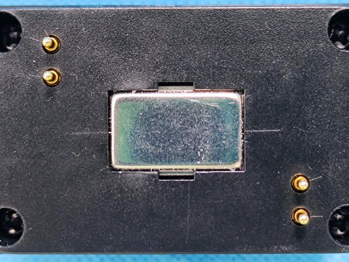
Click to zoom
Application Details
- Equipment Class
- FDS - Part 15 Field Disturbance Sensor
- Date of Grant
- Jun 06, 2022
- Application Purpose
- Original Equipment
- Date of Application
- Jun 06, 2022
- Equipment Note
- W System-Sensor
- Frequency Range
- 10525.00000000 - 10525.00000000
- Company
- WAC LIGHTING CO
- Country
- China
Documents & Files
Document Text
Text extracted from the exhibit documents filed with the FCC. Open a document above to read the original.
Users Manual
1WAC Lighting retains the right to modify the design of our products at any time as part of the company's continuous improvement program. G0 waclighting.com Phone (800) 526.2588 Fax (800) 526.2585 Headquarters/Eastern Distribution Center 44 Harbor Park Drive Port Washington, NY 11050 Central Distribution Center 1600 Distribution Ct Lithia Springs, GA 30122 Western Distribution Center 1750 Archibald Avenue Ontario, CA 91760 CAUTION: TO PREVENT ELECTRICAL SHOCK, ENSURE ELECTRICITY HAS BEEN TURNED OFF A T THE CIRCUIT BREAKER BEFORE BEGINNING. -Read all instructions before installing. -System is intended for installation by a licensed electrician in accordance with the National Electrical Code (NEC) and local regulations. -Retain installation instructions for future maintenance reference. DE COMMENCER. -Lisez toutes les instructions avant l’installation. -Le système doit être installé par un électrici en licensié conformément au code national de l ’éle ctr icité (NEC), et également aux règlement s l ocaux. SPECIFICATIONS Input:48VDC Installation:WAC STRUT System Control:Via WAC STRUT Connected Power Unit. SENSOR OVERVIEW STRUT Sensor is intended for use on WAC Lighting’s STRUT Channel systems. MODELSTRUT SYSTEM S2SN-1-BK48VDC STRUT System 1 27 32 " 2 3 8 " 1 9 16 " INSTALLATION INSTRUCTIONS STRUT - Vacancy/Photo Sensor S2SN WARNING: All parts must be used as indicated in these instructions. This product is designed for use only with the supplied parts and/or accessories designated for use by WAC Lighting. Substitution of parts or accessories not designated for use with this product by WAC Lighting could result in personal injury or property damage, and will void the warranty. Contact an authorized dealer or the manufacturer if any parts are damaged or missing. MISE EN GARDE: POUR ÉVITER TOUT CHOC ÉLECTRIQUE, ASSUREZ-VOUS QUE LE DISJONCTEUR SOIT MIS HORS TENSION AVANT DE COMMENCER. A TTENTION: Toutes les pièces doivent être utilisées comme indiqué dans ces instructions. Ce produit est conçu pour être utilisé seulement avec les pièces et/ou accessoires fournis pour être utilisés avec les produits WAC Lighting. Remplacer des pièces ou accessoires non conçus pour ce produit WAC Lighting pourrait causer des dommages corporels ou matériels et pourrait également causer l’annulation de la garantie. Veuillez contacter un revendeur autorisé ou le fabricant si des pièces manquent ou sont endommagées. FCC Radiation Exposure Statement: This equipment complies with FCC radiation exposure limits set forth for an uncontrolled environment . This transmitter must not be co‐located or operating in conjunction with any other antenna or transmitter. Any Changes expressly or modifications not approved by the party responsible for compliance could void the user's authority to operate the equipment. This device complies with part 15 of the FCC Rules. Operation is subject to the following two conditions: (1) This device may not cause harmful interference, and (2) this device must accept any interference received, including interference that may cause undesired operation. 2WAC Lighting retains the right to modify the design of our products at any time as part of the company's continuous improvement program. G0 waclighting.com Phone (800) 526.2588 Fax (800) 526.2585 Headquarters/Eastern Distribution Center 44 Harbor Park Drive Port Washington, NY 11050 Central Distribution Center 1600 Distribution Ct Lithia Springs, GA 30122 Western Distribution Center 1750 Archibald Avenue Ontario, CA 91760 FIG. 1 FIG. 2 FIG. 4 FIG. 3 PREPARATION: 1. 2. INSTALLATION TO STRUT SYSTEM: The sensor features a STRUT adapter for power and mechanical connection to the installed STRUT channel system. 1. The sensor is polarity agnostic, and may be installed in STRUT channel in either orientation. (See FIG. 1). 2. Insert adapter into channel slot. Ensure the adapter is parallel to the channel during installation. Push the adapter into the channel FIG. 2). 3. 4. If removal or relocation is desired, remove from channel by gently pulling downards. (See FIG. 3). 5. Commission and calibrate sensor using STRUT app. (See FIG. 4). "CLICK" or INSTALLATION INSTRUCTIONS STRUT - Vacancy/Photo Sensor S2SN INTEGRATION INSTRUCTIONS 1. This module has been tested and found to comply with the FCC Part15.245 for Modular Approval. 2. This Modular Approval is limited to OEM installation for mobile and fixed applications only. The antenna installation and operating configurations of this transmitter, including any applicable source-based time- averaging duty factor. 3. The maximum antenna gain is 3.3dBi.For situations where the host manufacturer is responsible for the integral antenna, the integration instructions shall inform the installer that the antenna permanently attached to the unit which used in the host product. 4. When the module is installed in the host device, the FCC ID label must be visible through a window on the final device or it must be visible when an access panel, door or cover is easily removed. If not, a second label must be placed on the outside of the final device that contains the following text: ―Contains FCC ID:2APNFWAC000003 5. The Applicant:WAC LIGHTING CO uses various test mode programs for test set up which operate separate from production firmware. Host integrators should contact WAC LIGHTING CO for assistance with test modes needed for module/host compliance test requirements. 6. S2SN-1-BK's module is FCC authorized for the FCC Part15.245 listed on the grant, and that the host product manufacturer is responsible for compliance to any other FCC rules that apply to the host not covered by the product grant of certification. If the grantee markets their product as being Part 15 Subpart B compliant, then the grantee shall provide a notice stating that the final host product still requires Part 15 Subpart B compliance testing with the module installed. 7. The module is limited to use in the host. the limited module manufacturer reviews d…
Text truncated - open the document above for the full version.
Cover Letter(s)
WAC LIGHTING CO Add: No.390 Qingfeng RD, Qingxi TW Dongguan City, Guangdong Province China. Tel: +86-769-87311200 Fax: +86-769-87311250 Email: [email protected] Limited Modular Approval Letter Date:202 2-05 -20 FEDERAL COMMUNICATIONS COMMISSIONS Authorization and Evaluation Division 7435 Oakland Mills Road Columbia, MD 21046 We, WAC LIGHTING CO, hereby request Limited Modular Approval for Product: W System-Sensor (Model number: S2SN-1-BK, S2SN-1*), FCC ID:2APNFWAC000003.The EUT meets most of the requirement for modular approval as detailed in FCC 15.212. the requirements is described below: 1. The modular has no RF shielding, please refer to the EUT photo ,which was integrated into the host. 2. The modular transmitter has buffered modulation/data inputs, Buffered data inputs stage has been integrated in chip (Model:XBR816C). 3. The modular transmitter has its own power supply regulation. Please refer to the schematics. 4. Comply with the antenna requirements of Section 15.203 and 15.204(c), the modular have two PCB antennas permanently attached to the module, one is TX, the other is RX, the maximum gain is 3.3dBi. 5. The EUT was not tested in a stand-alone configuration, the device is tested in one specific host configuration. Please refer to report and setup photo exhibit for details. 6. The m odule labeled with its own FCC ID. 7. Comply wit h any specific rules or operating requirements that ordinarily apply to a complete transmitter and the manufacturer must provide adequate instructions along with the module to explain any such requirements. The necessary explanation to be complied with this requirement is contained in the user manual, please refers to the User Manual. 8. Comply with any applicable RF exposure requirements in its final configuration. Sincerely, Signature: Printer Name:Xiongkang Liu Title:Director
External Photos
EXHIBIT B - EUT EXTERNAL PHOTOGRAPHS
Internal Photos
EXHIBIT C - EUT INTERNAL PHOTOGRAPHS RX Antenna TX Antenna
Test Report
TEST REPORT Applicant: WAC LIGHTING CO Address: No.390 Qingfeng RD,Qingxi TW Dongguan City, Guangdong Province, China FCC ID: 2APNFWAC000003 Product Name: W System-Sensor Model Number: S2SN-1-BK, S2SN-1* Standard(s): 47 CFR Part 15, Subpart C(15.245) ANSI C63.10-2013 The above equipment has been tested and found compliance with the requirement of the relative standards by China Certification ICT Co., Ltd (Dongguan) Report Number: CR22030057-00 Date Of Issue: 2022-04-19 Reviewed By: Sun Zhong Title: Manager Test Laboratory: China Certification ICT Co., Ltd (Dongguan) No. 113, Pingkang Road, Dalang Town, Dongguan, Guangdong, China Tel: +86-769-82016888 China Certification ICT Co., Ltd (Dongguan) Report No.: CR22030057-00 Page 2 of 30 Test Facility The Test site used by China Certification ICT Co., Ltd (Dongguan) to collect test data is located on the No. 113, Pingkang Road, Dalang Town, Dongguan, Guangdong, China. The lab has been recognized as the FCC accredited lab under the KDB 974614 D01 and is listed in the FCC Public Access Link (PAL) database, FCC Registration No. : 442868, the FCC Designation No. : CN1314. The lab has been recognized by Innovation, Science and Economic Development Canada to test to Canadian radio equipment requirements, the CAB identifier: CN0123. Declarations China Certification ICT Co., Ltd (Dongguan) is not responsible for the authenticity of any test data provided by the applicant. Data included from the applicant that may affect test results are marked with a triangle symbol “▲”. Customer model name, addresses, names, trademarks etc. are not considered data. Unless otherwise stated the results shown in this test report refer only to the sample(s) tested. This report cannot be reproduced except in full, without prior written approval of the Company. This report is valid only with a valid digital signature. The digital signature may be available only under the Adobe software above version 7.0. This report may contain data that are not covered by the accreditation scope and shall be marked with an asterisk “★”. China Certification ICT Co., Ltd (Dongguan) Report No.: CR22030057-00 Page 3 of 30 CONTENTS TEST FACILITY .......................................................................................................................................... 2 DECLARATIONS .......................................................................................................................................... 2 1. GENERAL INFORMATION .................................................................................................... 4 1.1 PRODUCT DESCRIPTION FOR EQUIPMENT UNDER TEST (EUT) ....................................................... 4 1.2 DESCRIPTION OF TEST CONFIGURATION ........................................................................................... 5 1.2.2 Support Equipment List and Details .............................................................................................................. 5 1.2.3 Support Cable List and Details ...................................................................................................................... 5 1.2.4 Block Diagram of Test Setup ......................................................................................................................... 5 1.3 MEASUREMENT UNCERTAINTY .......................................................................................................... 7 2. SUMMARY OF TEST RESULTS ............................................................................................ 8 3. REQUIREMENTS AND TEST PROCEDURES .................................................................... 9 3.1 AC LINE CONDUCTED EMISSIONS ...................................................................................................... 9 3.1.1 Applicable Standard ....................................................................................................................................... 9 3.1.2 EUT Setup.................................................................................................................................................... 10 3.1.3 EMI Test Receiver Setup ............................................................................................................................. 10 3.1.4 Test Procedure ............................................................................................................................................. 11 3.1.5 Corrected Amplitude & Margin Calculation ................................................................................................ 11 3.2 RADIATION SPURIOUS EMISSIONS .................................................................................................... 12 3.2.1 Applicable Standard ..................................................................................................................................... 12 3.2.2 EUT Setup.................................................................................................................................................... 13 3.2.3 EMI Test Receiver & Spectrum Analyzer Setup ......................................................................................... 14 3.2.4 Test Procedure ............................................................................................................................................. 15 3.2.5 Corrected Amplitude & Margin Calculation ................................................................................................ 15 3.3 20 DB BANDWIDTH ............................................................................................................................. 16 3.3.1 Applicable Standard ..................................................................................................................................... 16 3.3.2 EUT Setup..................................................................................................................................…
Text truncated - open the document above for the full version.
Test Setup Photos
EXHIBIT D - TEST SETUP PHOTOGRAPHS Conducted emissions front View Conducted emissions side View Radiated Emission Below 1GHz View Radiated Emission Below 1GHz View Radiated Emissions Above 1G front View(1G-18G) Radiated Emissions Above 1G rear View(18G-26.5G) Radiated Emissions Above 1G View(26.5G-40G)
Contact Information
Applicant
Xiongkang Liu
Test Firm
CHINA CERTIFICATION ICT CO., LTD (DONGGUAN)Tanie Ou
[email protected]0086 0769 86858888
Technical Specifications
| # | Rule Parts | Frequency Range | Power Output |
|---|---|---|---|
| 1 | 15.245 | 10.53 GHz - 10.53 GHz | - |
Other Applications from WAC LIGHTING CO
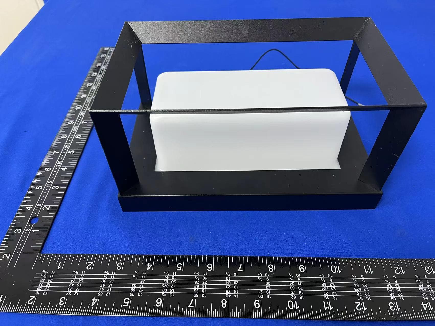
2APNF-IWL102
Apr 09, 2023LongBoxSmart(Bluetooth)WallSconcet
Equipment Class
DTS - Digital Transmission System
2APNFWAC000004
Jan 29, 2023Smart Wall Light
Equipment Class
DTS - Digital Transmission System