2APVD-C525PBUSmart Baby Monitor
PerimeterSafe Home Monitoring Limited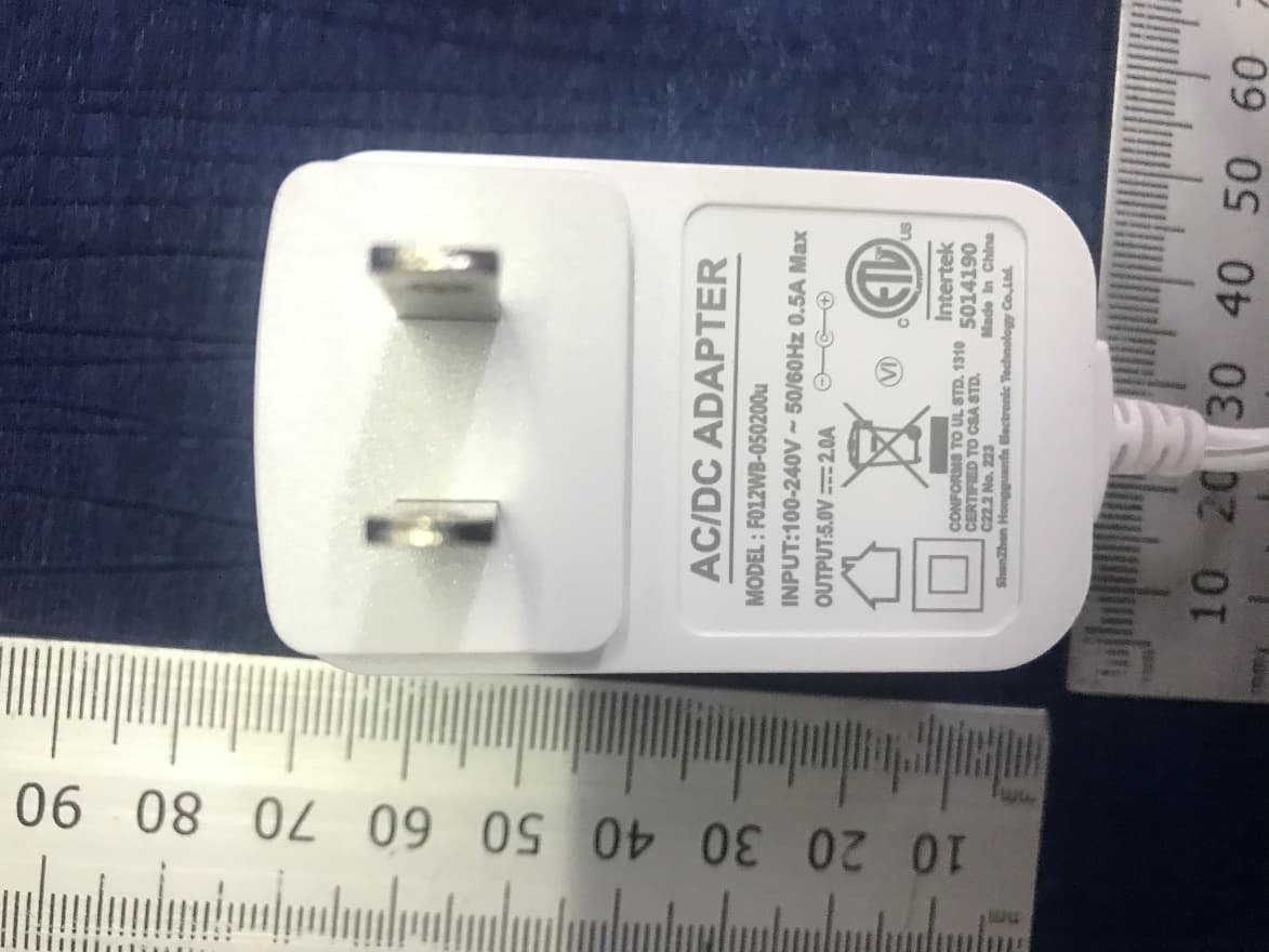
Click to zoom
Application Details
- Equipment Class
- DTS - Digital Transmission System
- Date of Grant
- Jul 31, 2021
- Application Purpose
- Original Equipment
- Date of Application
- Jul 12, 2021
- Equipment Note
- Smart Baby Monitor
- Frequency Range
- 2422.00000000 - 2452.00000000
- Country
- Canada
Documents & Files
Document Text
Text extracted from the exhibit documents filed with the FCC. Open a document above to read the original.
Users Manual
EN_C525P_V1 KODAK SMART BABY MONITOR C525P Page | 2Introduction 1 x Parent Unit 1 x Power adapter for Parent Unit 1 x Camera 84mm 162mm C525P 120mm 60mm ASSEMBLY Thank you for buying the KODAK SMART BABY MONITOR. With the Baby Monitor’s Parent Unit or your mobile device, now you can monitor your baby sleeping in another room anywhere, anytime! Please keep your original dated sales receipt. You will need to produce a copy of it to confirm your warranty status. For product-related questions, please send an email to: [email protected]. This User Manual covers all the information you will need to get the most out of your product. Prior to using the Baby Monitor, we recommend that you fully charge the battery in the Parent Unit. This way, the device will continue to work even if you disconnect it from the power supply to carry it to another location. Please read the Safety Instructions on page 18 carefully before installation. Check List: WELCOME Page | 4Parent Unit Overview PARENT UNIT OVERVIEW Keys a. b. c. d. e. f. g. h. : Press and hold to speak to your baby : Press to enter/exit the Menu mode : Press to turn on/off the LCD display : Press to confirm : Press to scroll/pan left : Press to scroll/pan right : Press to scroll/pan down : Press to scroll/pan up 1. Battery Status Indicator 2. Antenna 3. Volume Up 4. Volume Down 5. Power On/Off Slider 6. Display (LCD Screen resolution 800x480) 7. Microphone a b d f h c e g 2 6 1 3 4 5 7 i Page | 6Behaviors for Parent Unit Beep Behaviors for Parent Unit 2 Quick BeepsThe parent Unit may be disconnected from the Camera due to being out of range or the Camera may be powered off. 1 BeepLow Battery Alert. It is time to recharge the battery on Parent Unit. 5 Continuous BeepsTemperature is out of range. The first LED lights up in blue/purple when the adapter is plugged in and it’s fully charged; the second LED lights up in green when the Parent Unit is switched on. The first LED lights up in red when it’s charging and the adapter is plugged in; the second LED lights up in green when the Parent Unit is switched on. When the third and fourth LED light up in yellow, the Camera is detecting and transmitting sounds to the parent unit. LED BEHAVIORS FOR PARENT UNIT When the fifth and sixth LED light up in red, high volume sounds detected and transmitted Page | 8KODAK Smart HomeCamera Overview 9 6 5 KODAK SMART BABY MONITOR C525P CAMERA OVERVIEW 3 1 2 4 1. IR Sensor 2. Camera Lens (with resolution HD(720p)) 3. Lens Frame with Tilt function (up for 90°, down for 15°) 11. Power ON/OFF Switch 12. Holes for Wall Mount 13. Micro-SD Card Cover (Only up to 32GB - Class 10 memory card) 14. Thermometer 13 14 4. Pan function (330°) 5. LED Power Indicator 6. Charging Socket 7. Speaker 8. Microphone 9. Antenna 10. Pair Button 8 10 7 11 12 Camera OverviewPage | 10 9mm 1. First, put the screws on the wall. The diame- ter of the screws should be at least 5mm and maximum of 9mm. The distance between two screws should be 20mm. 2. Place and match the wider holes on the base of the camera with the screws. 3. Slide the base of the camera downwards so that the screws lock towards the narrow side. 20mm INSTRUCTIONS OF HOW TO WALL MOUNT YOUR C525P CAMERA Page | 12Behaviors for Camera LED Behaviors for Camera(C525P) Camera is OFF, connected adapter: Solid Red Camera powering up: Solid Blue for first few seconds Camera locating router: Blue blinking every one second Camera connected to router: Solid Blue Camera in pair mode: Blinking Blue & Red Firmware upgrading. DO NOT SWITCH OFF THE CAMERA: Blinking Purple, Red & Blue Camera is OFF, battery is fully charged: No Light Page | 14Guidelines to Install Your Baby Monitor ESSENTIAL GUIDELINES FOR THE INSTALLATION OF YOUR BABY MONITOR Guidelines to Install Your Baby Monitor • Before using your Camera and the Parent Unit together, you must first establish a radio link between them. The range may be affected by environmental conditions. • Any large metal object such as refrigerator, mirror, filing cabinet, metallic door or reinforced concrete between the Camera and the Parent Unit may block the radio signal. • The strength of the signal may also be reduced by other solid structures such as walls or electrical appliances (including radios, TVs, computers, cordless or mobile phones, fluorescent lights or dimmer switches). • The use of other 2.4 GHz products (e.g. wireless networks [Wi-Fi routers], Blue-tooth systems, or microwave ovens) may cause interference with this product. Therefore, always keep the Baby Monitor at least 5 feet/1.5 meters from such products, or turn them off if they appear to be causing interference. • If the signal is weak, try moving the Parent Unit and/or the Camera to another position in the room or bring them near the router in case of the monitor uses router mode connection” • Insert one of the in-box batteries into the Parent Unit. The battery should be inserted with the label facing • Insert one of the in-box batteries in the bottom of the Camera. The battery should be inserted with the label facing downwards. Page | 16Table of Contents TABLE OF CONTENTS 1. Safety Instructions 2. Getting Started 2.1 Camera Power Supply 2.2 Parent Unit Power Supply 2.3 Registration (Pairing) 3. Using the Baby Monitor 3.1 Setting Up 3.2 Power On or Off the Camera 3.3 Power On or Off the Parent Unit 3.4 Talk Mode 3.5 Video On/Off 4. Parent Unit Menu Options 4.1 Snapshot 4.2 Add (Pair) a Camera 4.3 Set Wi-Fi network connection between the Camera and the Parent unit 4.4 Set 12 or 24 hour Time Format 4.5 Melody 4.6 Temperature 4.7 Brightness 4.8 Camera Loop 4.9 Zoom 4.10 Outdoor / Indoor Mode 4.11 Voice Activation 4.12 Volume 4.13 Split Screen 5. Proper Disposal of the Device 6. Cleaning Your Device 7. Troubleshooting 8. “KODAK Smart Home” In-App Setup 9. Monitoring Your Baby Via the App 10. Grant Access 11. Zone Detection 12. Timeline 14. Further Information • Exclusions from Coverage • How to Obtain Warranty Service or Other I…
Text truncated - open the document above for the full version.
Users Manual
Page | 56Parent Unit Options 4.13 SPLIT SCREEN 1. Press “ ” on the Parent Unit for the menu bar. 2. Press “ ” or “ ” button to select “ “, then press “ ” to proceed to the next step. If there is only one connecting camera, there will be a message "Please add more monitor to use this feature" 3. The screen will split to left screen and right screen. 4. The left screen shows the current camera. 5. The right screen shows the camera number of the next available camera. 6. If there are more than 3 cameras (max4), you can press “ ” or “ ” button to select another camera " " ," "," "," "within 10 seconds. 7. Press “ ” to apply. Note Please pair the camera via Wi-Fi with the KODAK Smart Home App to get the latest firmware version for this feature. • The audio of camera on the left screen has higher priority to be played on the Parent Unit. If both cameras have sound at the same time, you will hear the audio from the left screen camera, whereas the right camera will show the sound detection icon on. If the left camera has no sound and the right one does then the audio of the right camera will play as normal. • When in split screen mode, talk mode, " ", " ", " " and Pan-Tilt Zoom function(C525P) are disabled on the Parent Unit. • All battery/temperature alerts (if any) are for the camera selected and shown on the left screen. • The camera number on the left screen cannot be modified. You can change the camera on the left screen by viewing it first before turning ON the Important Information 1. Sound Indication (Audio output coming from selected camera number) 2. Sound Detection (Sound is detected on the selected camera number) 3. Camera Numbers Page | 58Parent Unit Options 12 3 ICON DEFINITION OF SPLIT SCREEN Page | 60Disposal of The DeviceCleaning When the product comes to the end of its lifecycle, you should not dispose of it with normal household waste. Take the product to a collection point for the recycling of its electrical and electronic components. This is indicated by the symbol on the product, User Manual and/or packaging. Some of the product materials may be reused if you take them to a recycling point. By reusing some parts or raw materials from used products, you make a significant contribution to environmental conservancy. Please contact your local authorities if you require any further information on the collection points in your area. Please dispose of the battery pack in an environmentally-friendly manner in accordance with your local regulations. 5. PROPER DISPOSAL OF THE DEVICE Wipe your Baby Monitor with a slightly moistened or anti-static cloth. Refrain from using cleaning agents or abrasive solvents. Cleaning and Maintenance • Never clean any part of the product with thinners or other solvents and chemicals – this may result in permanent damage to the product which is out of the scope of coverage of the Warranty. • Make sure that your Baby Monitor stays away from hot, humid areas or conditions, strong sunlight and avoid moisture. 6. CLEANING YOUR DEVICE Note: • Always turn off and disconnect the power adapter prior to cleaning your Baby Monitor. • We have made every effort to ensure that your Baby Monitor is highly reliable. Yet, if anything goes wrong, please do not try to repair it yourself. Instead, please contact our Customer Support team for help at [email protected] or visit www. kodaksmarthome.com/support Page | 62Troubleshooting We suggest to pair the camera via Wi-Fi with the KODAK Smart Home App to get the latest firmware version for your devices Power Indicator on the Parent Unit does not come on • Check whether the Parent Unit is powered on. • Check whether the battery is charged. • Recharge the Parent Unit by connecting it to the power supply. The Parent Unit beeps repeatedly • The Parent Unit and the Camera may be out of range with each other. • Reduce the distance between the units, but not closer than 3 feet/0.9 meters. • The Camera may be switched off. Slide the ON/OFF switch to the ON position to switch on the Camera. • The battery in the Parent Unit is running low. Connect the Parent Unit to an electrical outlet with the supplied power adapter to recharge the battery. The Battery icon on the Parent Unit flashes 7. TROUBLESHOOTING • The Parent Unit maybe running low on battery. Connect the Parent Unit to an electrical outlet with the supplied power adapter to recharge the battery. Unable to hear sound or baby crying from the Parent Unit • The volume level in the Parent Unit may be set too low. Refer to section 4.12 for volume level settings. • The Parent Unit and the monitoring Camera may be out of range with each other. Reduce the distance between the units, but not closer than 3 feet/0.9 meters. The baby monitor system produces a high-pitched noise • The Parent Unit and the Camera are too close to each other. Make sure the Parent Unit and Camera are at least 3 feet/0.9 meters away from each other. • The speaker volume of the Parent Unit may be set too high. Decrease the volume of the Parent Unit. Page | 64Troubleshooting Battery life in the Parent Unit runs low quickly • The LCD brightness may be set too high. Try to decrease the brightness level. Refer to section 4.7 for details. • The volume level of the Parent Unit may be set too high, which consumes power. Decrease the volume level of the Parent Unit. Refer to section 4.12 for volume level settings. Parent Unit image is not in color • If the Camera is placed in a dark room, it will turn ON infra-red illumination and the picture image changes from ‘color’ to ‘black and white’. When the room becomes brighter, the picture will resume back to ‘color’. There is no transmission from the Camera to the Parent Unit • Switch on both the Camera and Parent Units. • Pair the Camera again as described in see “4.2.1 Add (Pair) a Camera”. • If there is no free camera location, delete a location first, as described in see “4.2.2 Delete a Camera”. The Parent Unit is in standby • To turn on the Parent Unit scree…
Text truncated - open the document above for the full version.
Cover Letter(s)
QF094234 Page 1 of 1 Revision 0 Authority to Act as Agent Date: 2021-04-13 TUV Rheinland Group 762 Park Avenue Youngsville, NC 27596 To Whom It May Concern: I appoint TUV Rheinland (Shenzhen) Co., Ltd. to act as our agent in the preparation of this application for equipment certification. I certify that submitted documents properly describe the device or system for which equipment certification is sought. I also certify that each unit manufactured, imported or marketed, as defined in the FCC or Industry Canada’s regulations will have affixed to it a label identical to that submitted for approval with this application. For instances where our authorized agent signs the application for certification on our behalf, I acknowledge that all responsibility for complying with the terms and conditions for Certification, as specified by TUV Rheinland Group, still resides with PerimeterSafe Home Monitoring Limited / The Atrium, 1321 Blanshard Street, Suite 301, Victoria, British Columbia, BC V8W 0B For TCB applications, We certify that we are not subject to denial of federal benefits, that includes FCC benefits, pursuant to Section 5301 of the Anti-Drug Abuse Act of 1988, 21 U.S.C. 862. Further, no party, as defined in 47 CFR 1.2002 (b), to the application is subject to denial of federal benefits, that includes FCC benefits. Thank you, Agency Agreement Expiration Date: 12 months By : Eric Lee (Print Name) Title : VP of Product Development Telephone : 94982915 On behalf of : PerimeterSafe Home Monitoring Limited (Company Name)
Cover Letter(s)
Standard Form Sample Request for Confidentiality Letter MS-0044715 Page 1 of 1 Revision 0 The following is a sample Confidentiality Request letter, which needs to be completed on company letterhead, signed by an authorized Applicant/Agent, and submitted to TÜV Rheinland. Date: 2021-04-13 Subject: Confidentiality Request for FCC ID: 2APVD-C525PBU and IC: 23907-C525PBU Pursuant to FCC 47 CRF 0.457(d) and 0.459 and IC RSP-100, Section 10, the applicant requests that a part of the subject FCC/IC application be held confidential. Type of Confidentiality Requested Exhibit Short Term Permanent Block Diagrams Short Term Permanent Internal Photos *** Short Term Permanent Operation Description/Theory of Operation Short Term Permanent Tune-Up Procedure Short Term Permanent Schematics Short Term Permanent User’s Manual*** Short Term n/a Test Setup Short Term n/a External Photos PerimeterSafe Home Monitoring Limited has spent substantial effort in developing this product and it is one of the first of its kind in industry. Having the subject information easily available to "competition" would negate the advantage they have achieved by developing this product. Not protecting the details of the design will result in financial hardship. Permanent Confidentiality: The applicant requests the exhibits listed above as permanently confidential be permanently withheld from public review due to materials that contain trade secrets and proprietary information not customarily released to the public. (*** PAG only) Short-Term Confidentiality: The applicant requests the exhibits selected above as short term confidential be withheld from public view for a period of 180 days from the date of the Grant of Equipment Authorization and prior to marketing. This is to avoid premature release of sensitive information prior to marketing or release of the product to the public. Applicant is also aware that they are responsible to notify TUV Rheinland in the event information regarding the product or the product is made available to the public. TUV Rheinland will then release the documents listed above for public disclosure pursuant to FCC Public Notice DA 04-1705. Sincerely, By: _________________________________ Eric Lee (Signature/Title) (Print name) VP of Product Development
Cover Letter(s)
Difference Declaration Original Model No.:C525P Adding Model No.:C125P To whom it may concern, We, PerimeterSafe Home Monitoring Limited would like to declare those models C525P, C125P are identical in electrical circuit design and PCB layout.The only difference are model name: Sincerely yours, Applicant:PerimeterSafe Home Monitoring Limited Address: The Atrium, 1321 Blanshard Street, Suite 301 Victoria, British Columbia, BC V8W 0B6, Victoria, Canada Signature: Name and title:Eric Lee / VP of Product Development Email:[email protected] Tel.:+852-94982915
External Photos
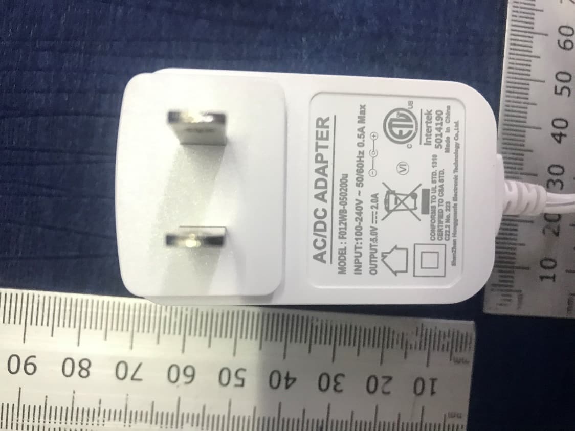
Page 1 of 4 Fig. 1.Camera overall view -1 Fig. 2.Camera overall view -2 Page 2 of 4 Fig. 3.Camera overall view -3 Fig. 4.Camera overall view -4 Wifi antenna 2412-2462MHz Page 3 of 4 Fig. 5.Camera overall view -5 Fig. 6.Camera overall view -6 Page 4 of 4 Fig. 7.Adapter model F012WB-050200u (US plug)
ID Label/Location Info
30X18mm Rating Label 1) Colour: White background black letters 2) Material: adhesive label with plastic lamination on top 3) Size : 45 x 6mm(On Unit) UDID Label X8mm Serial Number label Format: 1st place L: Factory code, at present, use L for Luxshare 2nd place B: Model-Brand, 3rd place N: Series-pack , use N for C125P, 4th & 5th place YY: year, 6th & 7th place WW: based on calendar 8th – 12th place: sequential ascending numbering, starting with 00001 X5mm SN Label Made in China IC: 23907-C525PBU HVIN:C525PBU KODAK CHERISH C125P Smart Baby Camera Input: 5V 2000mA Use only Power Supplies listed in the user’s guide. FCC ID: 2APVD-C525PBU Made in China IC: 23907-C525PBU HVIN:C525PBU KODAK CHERISH C125P Smart Baby Camera Input: 5V 2000mA Use only Power Supplies listed in the user’s guide. FCC ID: 2APVD-C525PBU 30X18mm Rating Label Serial Number label Format: 1st place L: Factory code, at present, use L for Luxshare 2nd place B: Model-Brand, 3rd place L: Series-pack , use L for C525P, 4th & 5th place YY: year, 6th & 7th place WW: based on calendar 8th – 12th place: sequential ascending numbering, starting with 00001 1) Colour: White background black letters 2) Material: adhesive label with plastic lamination on top 3) Size : 45 x 6mm(On Unit) X8mm UDID Label X5mm SN Label Made in China IC: 23907-C525PBU HVIN:C525PBU KODAK CHERISH C525P Smart Baby Monitor Input: 5V 2000mA Use only Power Supplies listed in the user’s guide. F CC ID: 2APVD-C525PBU Made in China IC: 23907-C525PBU HVIN:C525PBU KODAK CHERISH C525P Smart Baby Monitor Input: 5V 2000mA Use only Power Supplies listed in the user’s guide. F CC ID: 2APVD-C525PBU
Internal Photos
Page 1 of 11 Fig. 1.Camera internal view -1 Fig. 2.Camera internal view -2 Page 2 of 11 Fig. 3.Camera internal view -4 Fig. 4.Camera internal view -5 Page 3 of 11 Fig. 5.Camera internal view -6 Fig. 6.Camera internal view -7 Page 4 of 11 Fig. 7.Camera internal view -8 Fig. 8.Camera PCB view -1 Page 5 of 11 Fig. 9.Camera PCB view -2 Fig. 10.Camera PCB view -3 Page 6 of 11 Fig. 11.Camera PCB view -4 Fig. 12.Camera PCB view -5 Page 7 of 11 Fig. 13.Camera PCB view -6 Fig. 14.Camera PCB view -7 Page 8 of 11 Fig. 15.Camera PCB view -8 Fig. 16.Camera PCB view -9 Page 9 of 11 Fig. 17.Motor view Fig. 18.WIFI module Page 10 of 11 Fig. 19.WIFI module Fig. 20.WIFI antenna Page 11 of 11 Fig. 21.WIFI antenna
RF Exposure Info
Safety Human Exposure 1Radio Frequency Exposure Compliance 1.1Electromagnetic Fields RESULT:Pass Test Specification Test standard: CFR47 FCC Part 2: Section 2.1091 CFR47 FCC Part 1: Section 1.1310 FCC KDB Publication 447498 v06 FCC KDB Publication 865664 D01 v01r04 FCC KDB Publication 865664 D02 v01r02 RSS-102 Issue 5 March 2015 1.1.1RF Exposure Compliance Requirement for FCC (FCC ID: 2APVD-C525PBU) FCC requirement: Systems operating under the provisions of this section shall be operated in a manner that ensures that the public is not exposed to radio frequency energy level in excess limit for maximum permissible exposure. In accordance with 47 CFR FCC Part 2 Subpart J, section 2.1091 this device has been defined as a mobile device whereby a distance of 20cm normally can be maintained between the user and the device. MPE Calculation Method according to KDB 447498 v06 Power Density: S (mW/cm 2 ) = PG/4πR 2 or EIRP/4πR 2 Where: S = power density (mW/cm 2 ) P = power input to the antenna (mW) G = power gain of the antenna in the direction of interest relative to an isotropic radiator R = distance to the center of radiation of the antenna (cm) The nominal maximum conducted output power specified: Wi-Fi 802.11 b/g/n: 18.90 dBm From the peak RF output power, the minimum mobile separation distance, d=20 cm, as well as the antenna gain (Max. 1.0 dBi for Wi-Fi 802.11 b/g/n), the RF power density can be calculated as below: For Wi-Fi 802.11 b/g/n: S (mW/cm 2 ) = PG/4πR 2 = 0.019 mW/cm 2 Limits for Maximum Permissible Exposure (MPE) according to FCC Part 1.1310: 1.0 mW/cm 2 1.1.2RF Exposure Compliance Requirement for IC (IC: 23907-C525PBU) The EUT shall comply with the requirement of RSS-102 section 2.5.2. Exemption from Routine Evaluation Limits – RF Exposure Evaluation RF exposure evaluation is required if the separation distance between the user and/or bystander and the device’s radiating element is greater than 20 cm, except when the device operates as follows: at or above 300 MHz and below 6 GHz and the source-based, time-averaged maximum e.i.r.p. of the device is equal to or less than 1.31 x 10 -2 ƒ 0.6834 W (adjusted for tune-up tolerance), where ƒ is in MHz; RF exposure evaluation exempted power for Wi-Fi 802.11 b/g/n: 2.670 W The nominal maximum conducted output power specified: Wi-Fi 802.11 b/g/n: 18.90 dBm Antenna Gain: 1.0 dBi for Wi-Fi 802.11 b/g/n The Max. e.i.r.p. for Wi-Fi 802.11 b/g/n: 19.90 dBm = 0.098 W The e.i.r.p. for Wi-Fi 802.11 b/g/n is less than the RF exposure evaluation exempted power. So RF exposure evaluation is not required. “RF Radiation Exposure Statement Caution: This Transmitter must be installed to provide a separation distance of at least 20 cm from all persons.”
Test Report
Prüfbericht - Produkte Test Report - Products Prüfbericht-Nr.: Test report no.: CN21KAW4 002 Auftrags-Nr.: Order no.: 168311525 Seite 1 von 21 Page 1 of 21 Kunden-Referenz-Nr.: Client reference no.: N/A Auftragsdatum: Order date: 2021-03-26 Auftraggeber: Client: PerimeterSafe Home Monitoring Limited The Atrium, 1321 Blanshard Street, Suite 301 Victoria, British Columbia, BC V8W 0B6, Victoria, Canada Prüfgegenstand: Test item: Cherish C525P (Baby unit) Bezeichnung / Typ-Nr.: Identification / Type no.: C525P, C125P (Trademark: Kodak) Auftrags-Inhalt: Order content: Test Report Prüfgrundlage: Test specification: CFR47 FCC Part 15: Subpart C Section 15.247 RSS-247 Issue 2 February 2017 RSS-Gen Issue 5 March 2019 Wareneingangsdatum: Date of sample receipt: 2021-04-16 Please refer to Photo Document Prüfmuster-Nr.: Test sample no: A003030057-001~012 A003031840-001~002 Prüfzeitraum: Testing period: 2021-04-16 – 2021-06-11 Ort der Prüfung: Place of testing: TÜV Rheinland (Shenzhen) Co., Ltd. Prüflaboratorium: Testing laboratory: TÜV Rheinland (Shenzhen) Co., Ltd. Prüfergebnis*: Test result*: Pass geprüft von: tested by: X Signed by: Alex Lan genehmigt von: authorized by: X Signed by: Winnie Hou Datum: Date: 2021-07-02 Ausstellungsdatum: Issue date: 2021-07-02 Stellung / Position: Senior Project Engineer Stellung / Position: Technical Certifier Sonstiges / Other: FCC ID: 2APVD-C525PBU IC: 23907-C525PBU HVIN: C525PBU Zustand des Prüfgegenstandes bei Anlieferung: Condition of the test item at delivery: Prüfmuster vollständig und unbeschädigt Test item complete and undamaged * Legende: 1 = sehr gut 2 = gut 3 = befriedigend 4 = ausreichend 5 = mangelhaft P(ass) = entspricht o.g. Prüfgrundlage(n) F(ail) = entspricht nicht o.g. Prüfgrundlage(n) N/A = nicht anwendbar N/T = nicht getestet * Legend: 1 = very good 2 = good 3 = satisfactory 4 = sufficient 5 = poor P(ass) = passed a.m. test specification(s) F(ail) = failed a.m. test specification(s) N/A = not applicable N/T = not tested Dieser Prüfbericht bezieht sich nur auf das o.g. Prüfmuster und darf ohne Genehmigung der Prüfstelle nicht auszugsweise vervielfältigt werden. Dieser Bericht berechtigt nicht zur Verwendung eines Prüfzeichens. This test report only relates to the a. m. test sample. Without permission of the test center this test report is not permitted to be duplicated in extracts. This test report does not entitle to carry any test mark. TÜV Rheinland (Shenzhen) Co., Ltd. 1601 R&D Room, 1602-1604, 17-18F, Building 7 Site C, Vanke Cloud City Phase I, Xingke First Street, Xili Street, Xili Community, Nanshan District, Shenzhen 518052, P.R. China Mail: [email protected] · W eb: www.tuv.com Prüfbericht - Produkte Test Report - Products Prüfbericht - Nr.: Test Report No. CN21KAW4 002 Seite 2 von 21 Page 2 of 21 Test Summary 5.1.1ANTENNA REQUIREMENT RESULT:Pass 5.1.2MAXIMUM PEAK CONDUCTED OUTPUT POWER RESULT:Pass 5.1.3CONDUCTED POWER SPECTRAL DENSITY RESULT:Pass 5.1.46DB BANDWIDTH RESULT:Pass 5.1.599% BANDWIDTH RESULT:Pass 5.1.6CONDUCTED SPURIOUS EMISSIONS MEASURED IN 100 KHZ BANDWIDTH RESULT:Pass 5.1.7RADIATED SPURIOUS EMISSION RESULT:Pass 5.1.8CONDUCTED EMISSION ON AC MAINS RESULT:Pass Prüfbericht - Produkte Test Report - Products Prüfbericht - Nr.: Test Report No. CN21KAW4 002 Seite 3 von 21 Page 3 of 21 Contents 1GENERAL REMARKS..........................................................................................................................4 1.1COMPLEMENTARY MATERIALS............................................................................................................4 2TEST SITES........................................................................................................................................5 2.1TEST FACILITIES................................................................................................................................5 2.2LIST OF TEST AND MEASUREMENT INSTRUMENTS................................................................................5 2.3TRACEABILITY...................................................................................................................................6 2.4CALIBRATION.....................................................................................................................................6 2.5MEASUREMENT UNCERTAINTY............................................................................................................7 2.6LOCATION OF ORIGINAL DATA............................................................................................................7 2.7STATUS OF FACILITY USED FOR TESTING............................................................................................7 3GENERAL PRODUCT INFORMATION.....................................................................................................8 3.1PRODUCT FUNCTION AND INTENDED USE............................................................................................8 3.2RATINGS AND SYSTEM DETAILS..........................................................................................................8 3.3INDEPENDENT OPERATION MODES......................................................................................................9 3.4NOISE GENERATING AND NOISE SUPPRESSING PARTS........................................................................9 3.5SUBMITTED DOCUMENTS....................................................................................................................9 4TEST SET-UP AND OPERATION MODES..............................................................................................10 4.1PRINCIPLE OF CONFIGURATION SELECTION.......................................................................................10 4.2TEST OPERATION AND TEST SOFTWARE...........................................................................................10 4.3SPECIAL ACCESSORIES AND AUXILIARY EQUIPMENT........................................................…
Text truncated - open the document above for the full version.
Test Report
Prüfbericht - Produkte Test Report - Products Appendix B CN21KAW4 002 Page 30 of 117 Prüfbericht - Produkte Test Report - Products Appendix B CN21KAW4 002 Page 31 of 117 Prüfbericht - Produkte Test Report - Products Appendix B CN21KAW4 002 Page 32 of 117 Appendix B.4: Test Results of Conducted Spurious Emissions Measured in 100 kHz Bandwidth Wi-Fi 802.11 b mode, 1 Mbps Prüfbericht - Produkte Test Report - Products Appendix B CN21KAW4 002 Page 33 of 117 Prüfbericht - Produkte Test Report - Products Appendix B CN21KAW4 002 Page 34 of 117 Prüfbericht - Produkte Test Report - Products Appendix B CN21KAW4 002 Page 35 of 117 Wi-Fi 802.11 g mode, 6 Mbps Prüfbericht - Produkte Test Report - Products Appendix B CN21KAW4 002 Page 36 of 117 Prüfbericht - Produkte Test Report - Products Appendix B CN21KAW4 002 Page 37 of 117 Prüfbericht - Produkte Test Report - Products Appendix B CN21KAW4 002 Page 38 of 117 Wi-Fi 802.11 n(HT20) mode, MCS0 Prüfbericht - Produkte Test Report - Products Appendix B CN21KAW4 002 Page 39 of 117 Prüfbericht - Produkte Test Report - Products Appendix B CN21KAW4 002 Page 40 of 117 Prüfbericht - Produkte Test Report - Products Appendix B CN21KAW4 002 Page 41 of 117 Wi-Fi 802.11 n(HT40) mode, MCS0 Prüfbericht - Produkte Test Report - Products Appendix B CN21KAW4 002 Page 42 of 117 Prüfbericht - Produkte Test Report - Products Appendix B CN21KAW4 002 Page 43 of 117 Prüfbericht - Produkte Test Report - Products Appendix B CN21KAW4 002 Page 44 of 117 Wi-Fi 802.11 b mode, Band Edge Prüfbericht - Produkte Test Report - Products Appendix B CN21KAW4 002 Page 45 of 117 Wi-Fi 802.11 g mode, Band Edge Prüfbericht - Produkte Test Report - Products Appendix B CN21KAW4 002 Page 46 of 117 Wi-Fi 802.11 n(HT20) mode, Band Edge Prüfbericht - Produkte Test Report - Products Appendix B CN21KAW4 002 Page 47 of 117 Wi-Fi 802.11 n(HT40) mode, Band Edge Prüfbericht - Produkte Test Report - Products Appendix B CN21KAW4 002 Page 48 of 117 Note: 1.This testing was carried out on different modulations, but only the worst case was presented in this report. 2. Testing was carried out within frequency range 9kHz to the tenth harmonics. The measurement results below 30MHz and 18GHz - 26.5GHz were greater than 20dB below …
Text truncated - open the document above for the full version.
Contact Information
Applicant
Alvin Wong
Technical Contact
Test Firm
TUV Rheinland (Shenzhen) Co., Ltd.Gina Yang
[email protected]86 755 8268 1497
Technical Specifications
| # | Rule Parts | Frequency Range | Power Output |
|---|---|---|---|
| 2 | 15C | 2.42 GHz - 2.45 GHz | 64.60 mW |
Other Applications from PerimeterSafe Home Monitoring Limited
2APVD-C525PPU
Jul 31, 2021Smart Baby Monitor
Equipment Class
DTS - Digital Transmission System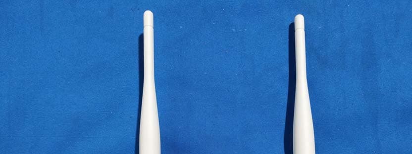
2APVD-R100
Apr 02, 2020KODAK CHERISH Range Extender
Equipment Class
DTS - Digital Transmission System