2APXH77548055NBA Jam
WF TASTEMAKERS TRADING LIMITED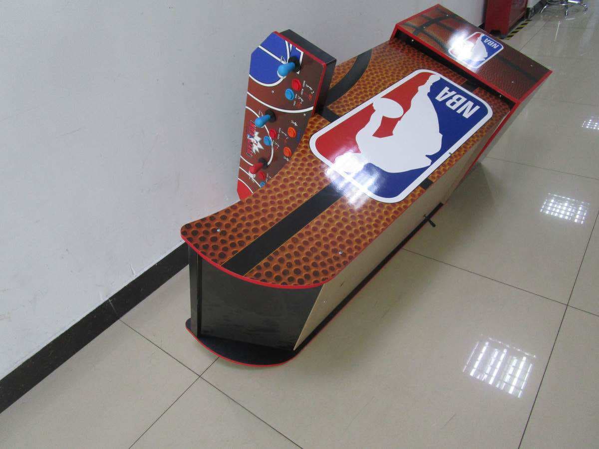
Click to zoom
Application Details
- Equipment Class
- DTS - Digital Transmission System
- Date of Grant
- Mar 26, 2020
- Application Purpose
- Original Equipment
- Date of Application
- Mar 26, 2020
- Equipment Note
- NBA Jam
- Frequency Range
- 2412.00000000 - 2462.00000000
- Country
- Hong Kong
Documents & Files
Document Text
Text extracted from the exhibit documents filed with the FCC. Open a document above to read the original.
Users Manual
5 32 1 4 ENGLISH TROUBLESHOOTINGTROUBLESHOOTING -Make sure all Wires/Plugs are properly connected and all the way set in as directed in assembly instructions. -Marquee power cord is not plugged in at the back of the monitor. -Marquee power cord is plugged into the wrong input. Marquee won’t light up. Game will not turn on. PROBLEMPOSSIBLE CAUSESOLUTION Game will turn ON, but there is no sound. You hear sound but there is no picture. -Make sure power cord is plugged into the wall outlet and there is power to that outlet. (Plug other electrical equipment into the power outlet to make sure the outlet normally works.) -Make sure all Wires/Plugs are properly connected and all the way set in as directed in assembly instructions. -Slide ON/OFF Switch located on control deck to the ON position. -Slide upload switch on back of monitor to the ON position. -Make sure all Wires/Plugs are properly connected and all the way set in as directed in assembly instructions. -Slide Volume Switch located on control deck to the right. NOTE: Push volume slide switch right to increase volume, left to lower volume. -Make sure all Wires/Plugs are properly connected and all the way set in as directed in assembly instructions. -Hold ON/OFF Switch OFF 5 seconds. -Make sure all Wires/Plugs are properly connected and all the way set in as directed in assembly instructions. -You may need to RESET the game. Turn the ON/OFF switch to the OFF position. Unplug the game from the wall outlet and wait 60 seconds to RESET the game. Plug the game back in and turn the ON/OFF switch back to ON. -Take something thin (like a business card) and place it between the button and the button housing and slide it back and forth to loosen the debris. -Look at the game control section in the instruction manual to make sure you are using the correct joystick or pressing the correct buttons to scroll through the game selection menu. -Look at the game control section in the instruction manual to make sure you are pressing the correct button to enter the game. -Look at the game control section in the instruction manual to make sure you are pressing the correct button to exit the game. -Make sure you are holding the exit button down for 5 seconds to exit the game. -Refer to the game control section in the instruction manual to see how many players are able to play that game. -Look at the game control section in the instruction manual to make sure you are pressing the correct game control buttons for that game. -Look at the game control loading screen on the monitor to make sure you are pressing the correct control buttons. (NOTE: The game controls that are printed on the control deck are only for the feature cabinet game. The other games in the cabinet will utilize the same buttons but react differently.) -Look at the game control section in the instruction manual to make sure you are pressing the correct button to start the game. The game screen looks pixelated or there are lines running through the image. The game screen is frozen. One of the buttons on the control deck is stuck in the down position. You are not able to scroll through the games on the game selection menu. You are able to scroll through the games on the game selection menu, but you can’t enter a game to begin playing. You have entered the game, but you can’t get the game to start. You have entered the game, but you can’t exit the game to get back to game selection menu. The control functions that are printed on the control deck do not match the gameplay on the screen for the game you are playing. The game will not let me select 2 or 3 players for a chosen game. -Wires/Plugs were hooked up incorrectly. -Debris may have gotten between the button and the button housing. -Power cord is not plugged into wall outlet. -Wires/Plugs are hooked up incorrectly. -ON/OFF Switch is in the OFF position. -Upload switch on back of monitor is in the OFF position. -Wires/Plugs were hooked up incorrectly. -Volume Switch is in the OFF position. -Wires/Plugs were hooked up incorrectly. -The game encountered a problem when processing the data. -You may be pressing the wrong button to enter the game. -You may be pressing the wrong button to exit the game. -You may not be holding down the exit button long enough. -You may be pressing the wrong game control buttons for the game you are playing. -The game may only be a 1 or 2 player game. -You may be pressing the wrong button to start the game. REV 01.14.20 GOLDEN TEE CLASSIC TM GOLDEN TEE 2K TM GOLDEN TEE ‘99 TM GOLDEN TEE ‘98 TM GOLDEN TEE CLASSIC TM GOLDEN TEE 2K TM GOLDEN TEE ‘99 TM GOLDEN TEE ‘98 TM MORTAL KOMBAT TM MORTAL KOMBAT 2 TM ULTIMATE MORTAL KOMBAT 3 TM MORTAL KOMBAT TM MORTAL KOMBAT 2 TM ULTIMATE MORTAL KOMBAT 3 TM FINAL FIGHT TM 1944 THE LOOP MASTER TM GHOSTS ‘N GOBLINS TM STRIDER TM FINAL FIGHT TM 1944 THE LOOP MASTER TM GHOSTS ‘N GOBLINS TM STRIDER TM TEENAGE MUTANT NINJA TURTLES ® TURTLES IN TIME TEENAGE MUTANT NINJA TURTLES ® TURTLES IN TIME FROGGER TIME PILOT TIME PILOT 84 FROGGER TIME PILOT TIME PILOT 84 GOLDEN TEE® GOLF, ITS®, INCREDIBLE TECHNOLOGIES®, IT®, and IT Incredible TECHNOLOGIES® are the properties of Incredible Technologies, Inc. All Rights Reserved. © Copyright 2018 Incredible Technologies, Inc. All Rights Reserved. Unauthorized duplication is a violation of apllicable law. All other marks are the properties of their respective owners. All Rights Reserved. MORTAL KOMBAT KLASSIC and all related characters and elements © & ™ Warner Bros. Entertainment Inc. WB GAMES LOGO: TM & © WBEI. (s15) ©2020 Viacom International Inc. All Rights Reserved. Nickelodeon, Teenage Mutant Ninja Turtles and all related titles, logos and characters are trademarks of Viacom International Inc. FINAL FIGHT® ©CAPCOM U.S.A., INC. 1989, 2019 ALL RIGHTS RESERVED. 1944: THE LOOP MASTER ©CAPCOM CO., LTD. 2000, 2019 ALL RIGHTS RESERVED. GHOSTS ‘N GOBLINS® ©CAPCOM CO., LTD. 1985, 2019 ALL RIGHTS RESERVED. STRIDER® ©MOTO KIKAKU. ©CAPCOM CO., LTD. 1989, 2019…
Text truncated - open the document above for the full version.
External Photos
Page 1 of 3 External Photos Page 2 of 3 Page 3 of 3
ID Label/Location Info
Page 1 of 1 Label Artwork and Location SIZE: 170mm (W) x 170mm (H)
Internal Photos
Page 1 of 8 Internal Photos WiFi ANT Page 2 of 8 Page 3 of 8 Page 4 of 8 Page 5 of 8 Page 6 of 8 Page 7 of 8 Page 8 of 8
RF Exposure Info
INTERTEK TESTING SERVICES FCC ID: 2APXH77548055 RF Exposure Report The Equipment Under Test (EUT) is a NBA Jam with Wi-Fi function operating at 2412-2462MHz for 802.11g/n-HT20, 11 channels with 5MHz channel spacing. The EUT is powered by DC 12V with AC/DC adaptor. For more detailed features description, please refer to the user’s manual. Modulation Type: CCK, BPSK, QPSK, 16QAM, 64QAM. Antenna Type: Integral Antenna Antenna Gain: 6dBi The nominal conducted output power specified: 21dBm (Tolerance: +/-3dB) The maximum conducted output power for the EUT is 23.9dBm in the frequency 2.462GHz 802.11g mode which is within the production variation. The minimum conducted output power for the EUT is 22.2dBm in the frequency 2.412GHz 802.11n-HT20 mode which is within the production variation. According to FCC Part 2.1091, this unlicensed transmitting devices is categorically excluded from routine environmental evaluation for RF exposure prior to equipment authorization or use, According to the KDB 447498 and OET 65, the simple calculation as below: For Maximum Permissible Exposure (MPE) evaluation of the product, the maximum power density at 20 cm from this transmitter shall be less than the General Population / Uncontrolled MPE limit in OET Bulletin 65. The maximum E.I.R.P= 21+3+6=30dBm=1000mW The source-based time averaged maximum radiated power = 1000 x Duty Cycle = 1000 mW From above data, the exposed power density at a distance (R) of 20cm from the center of radiation of the antenna can be calculated according to OET Bulletin 65 as follow: = 1000mW / 4πR^2 = 0.2 mW/cm^2 The MPE limit is 1.0 mW/cm^2 for general population and uncontrolled exposure in the Wi-Fi frequency range according to FCC Part 1.1310. As the measured power density at 20cm from the transmitter is lower than the MPE limit, the compliance to the MPE limit can be ensured by indicating the minimum 20cm separation between the transmitter's radiating structure and body of the user or nearby persons. INTERTEK TESTING SERVICES FCC ID: 2APXH77548055 Transmitter Duty Cycle Calculation The EUT transmit continuously during the test, the duty cycle is 1. The following RF exposure statement or similar sentence is proposed to be included in the user manual: “FCC RF Radiation Exposure Statement Caution: This Transmitter must be installed to provide a separation distance of at least 20 cm from all persons.”
Test Report
WF TASTEMAKERS TRADING LIMITED TEST REPORT SCOPE OF WORK FCC TESTING–7754 REPORT NUMBER SZHH01432686-001 ISSUE DATE [REVISED DATE] MARCH 3, 2020 [---------------------] PAGES 50 DOCUMENT CONTROL NUMBER FCC ID 247_b © 2017 INTERTEK Intertek Report No.: SZHH01432686-001 This report is for the exclusive use of Intertek's Client and is provided pursuant to the agreement between Intertek and its Client. Intertek's responsibility and liability are limited to the terms and conditions of the agreement. Intertek assumes no liability to any party, other than to the Client in accordance with the agreement, for any loss, expense or damage occasioned by the use of this report. Only the Client is authorized to permit copying or distribution of this report and then only in its entirety. Any use of the Intertek name or one of its marks for the sale or advertisement of the tested material, product or service must first be approved in writing by Intertek. The observations and test results in this report are relevant only to the sample tested. This report by itself does not imply that the material, product, or service is or has ever been under an Intertek certification program. Intertek Testing Service Shenzhen Ltd. Longhua Branch 101, 201, Building B, No. 308 Wuhe Avenue, Zhangkengjing Community GuanHu Subdistrict, LongHua District, Shenzhen, People’s Republic of China Tel: (86 755) 8601 6288 Fax: (86 755) 8601 6751 Version: 01-November-2017 Page: 1 of 50 FCC ID 247_b TEST REPORT WF TASTEMAKERS TRADING LIMITED Application For Certification FCC ID: 2APXH77548055 NBA Jam Additional name: NBA JAM-with LIGHTED MARQUEE, LIGHTED DECK, RISER & LICENSED STOOL Model: 7754 Additional Model: 8055 Brand Name: ARCADE 1 UP 2.4GHz Wi-Fi Transceiver Report No.: SZHH01432686-001 We hereby certify that the sample of the above item is considered to comply with the requirements of FCC Part 15, Subpart C for Intentional Radiator, mention 47 CFR [10-1-18] Prepared and Checked by: Approved by: Sign on file Terry Tang Kidd Yang Senior Engineer Technical Supervisor Date: March 3, 2020 Intertek Report No.: SZHH01432686-001 Version: 01-November-2017 Page: 2 of 50 FCC ID 247_b TEST REPORT MEASUREMENT/TECHNICAL REPORT NBA Jam Model: 7754 FCC ID: 2APXH77548055 This report concerns (check one) Original Grant X Class II Change Equipment Type: DTS - Part 15 Digital Transmission Systems (Wi-Fi transmitter portion) Deferred grant requested per 47 CFR 0.457(d)(1)(ii)? Yes No X If yes, defer until : date Company Name agrees to notify the Commission by: date of the intended date of announcement of the product so that the grant can be issued on that date. Transition Rules Request per 15.37? Yes No X If no, assumed Part 15, Subpart C for intentional radiator - the new 47 CFR [10-01-18] Edition] provision. Report prepared by: Terry Tang Intertek Testing Services Shenzhen Ltd. Longhua Branch 101, 201, Building B, No. 308 Wuhe Avenue, Zhangkengjing Community GuanHu Subdistrict, LongHua District, Shenzhen, People’s Republic of China Tel: (86 755) 8601 6288 Fax: (86 755) 8601 6751 Intertek Report No.: SZHH01432686-001 Version: 01-November-2017 Page: 3 of 50 FCC ID 247_b TEST REPORT Table of Contents 1.0 Summary of Test results ................................................................................................................. 4 2.0 General Description ......................................................................................................................... 5 2.1 Product Description ........................................................................................................................ 5 2.2 Related Submittal(s) Grants ........................................................................................................... 5 2.3 Test Methodology ........................................................................................................................... 5 2.4 Test Facility .................................................................................................................................... 5 3.0 System Test Configuration .............................................................................................................. 6 3.1 Justification .................................................................................................................................... 6 3.2 EUT Exercising Software ............................................................................................................... 6 3.3 Special Accessories ....................................................................................................................... 7 3.4 Measurement Uncertainty .............................................................................................................. 7 3.5 Equipment Modification .................................................................................................................. 7 3.6 Support Equipment List and Description ....................................................................................... 7 4.0 Measurement Results ...................................................................................................................... 8 4.1 Maximum Conducted Output Power at Antenna Terminals ............................................................... 8 4.2 Minimum 6 dB RF Bandwidth ......................................................................................................... 9 4.3 Maximum Power Density Reading ............................................................................................... 14 4.4 Out of Band Conducted Emissions ............................................................................................... 19 4.5 Out of Band Radiated Emissions .................................................................................................. 32 4.6 Transmitter Radiated Emissions in Restricted Bands ........................................................…
Text truncated - open the document above for the full version.
Test Setup Photos
Page 1 of 1 Radiated Photos (The EUT placed at the center of the turntable)
Test Setup Photos
Page 1 of 1 Conducted photos
Contact Information
Applicant
Chris Yip(Compliance Manager)
Technical Contact
Intertek Testing Services Shenzhen Ltd. Longhua brWilliam Chen
[email protected](86-755) 8614 0627
101, 201, Building B, No. 308 Wuhe Avenue, Zhangke · Shenzhen · China
Non-Technical Contact
Intertek Testing Services Shenzhen Ltd. Longhua brWilliam Chen
[email protected](86-755) 8614 0627
Test Firm
Intertek Testing Services Shenzhen Ltd. Longhua BrHolly Ou
[email protected]+86 755 86140691
Technical Specifications
| # | Rule Parts | Frequency Range | Power Output |
|---|---|---|---|
| 1 | 15C | 2.41 GHz - 2.46 GHz | 245.50 mW |
Other Applications from WF TASTEMAKERS TRADING LIMITED
2APXHGLDMID
Jul 30, 2024GOLDEN TEE 3D x MIDWAY XL
Equipment Class
DTS - Digital Transmission System2APXHIGB5G
Jul 29, 2024INFINITY GAME BOARD
Equipment Class
DTS - Digital Transmission System2APXHGLDBWDLX
Mar 27, 2024GOLDEN TEE DELUXE ARCADE MACHINE
Equipment Class
DTS - Digital Transmission System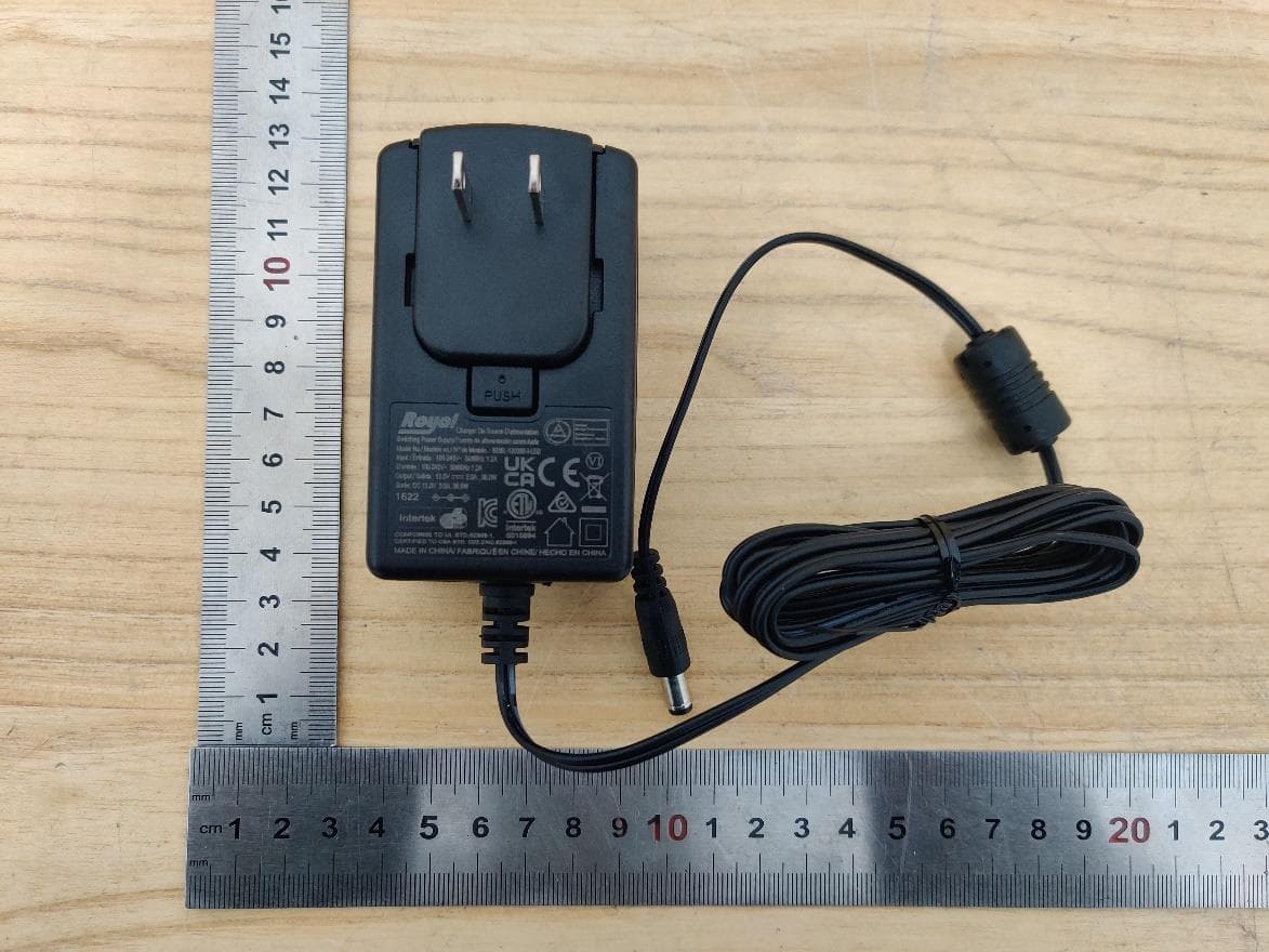
2APXHTMC
Oct 15, 2023TIME CRISIS DELUXE EDITION
Equipment Class
NII - Unlicensed National Information Infrastructure TX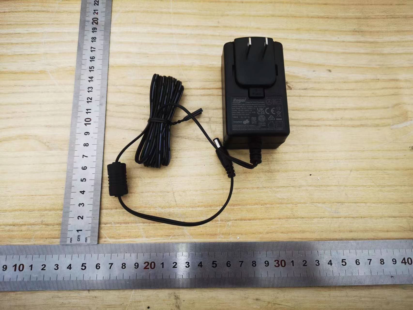
2APXHPABALE
Jun 08, 2022PAC-MANIATM LEGACY WITH RISER ARCADE1UP
Equipment Class
DTS - Digital Transmission System