2AQA6-H5041WiFi Gateway
Shenzhen Intellirocks Tech. Co., Ltd.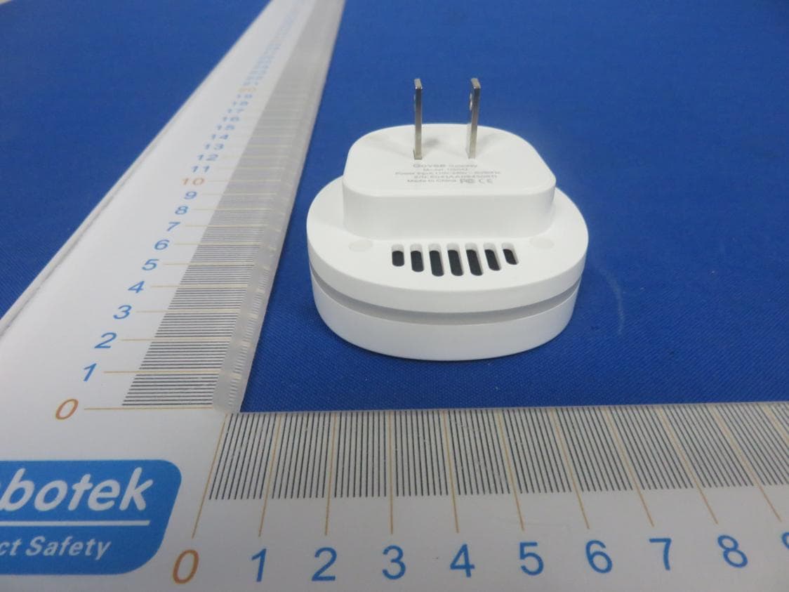
Click to zoom
Application Details
- Equipment Class
- DTS - Digital Transmission System
- Date of Grant
- Jul 26, 2020
- Application Purpose
- Original Equipment
- Date of Application
- Jul 26, 2020
- Equipment Note
- WiFi Gateway
- Frequency Range
- 2412.00000000 - 2462.00000000
- Country
- China
Documents & Files
Document Text
Text extracted from the exhibit documents filed with the FCC. Open a document above to read the original.
Users Manual
Using your device 0 Controlling your devices with the Govee Homeapp. -- . - ' F 1-1+1 -- . - ¾ [ 气 Calibration: Calibrate temp/humidity data Alarm me Alarm me '` Message Alert: App pushes alert messages once temp/humidity is beyond preset range. ( Export data ) Export Data: Export data in CSV format after filling in email and time slot. Temperature unit 匾 冒 o c Unit Switch: Switch temp unit in App {Note: Temp unit in export data is the same as that in App) 7 8 Add sensor Please refer to the following steps to add sensor or re-add sensor back: 1. Gateway enters into the pairing mode. / Red and blue indicator flash alternately. 2. Sensor sends the pairing signal. 勹 uffiJ ffl Pull out the batteries and then place batteries back. 3. Gateway receives the signal. ( ) - "" ""''""" ,,,�,, 4. Connection succeeded. (�} """"�···•'';� Attention: a. If you have not paired the gateway and sensor successfully within 30s, the gateway indicator will turn blue automatically and flash quickly, and then exit the pairing mode; b. If the connection fails, please carefully check the above steps and repeat the attempts. Troubleshooting and Warning Troubleshooting 1. The gateway could not be connected to the Wi-Fi network or the connection is unstable? a. Product supports only 2.4 GHz (not 5 GHz) network. b. Check the name of the network and the password. Please try to avoid special characters. c. The device should be placed within the coverage of the router signal. Please keep the distance between the gateway and the router in 30 meters (100ft). d. Reduce barriers like metal door or multiple/ heavy walls, gateway and the router in 30 meters (100ft). 2. The sensors do not work? a. Pull out the insulation sheet before using. b. Check the battery capacity. c. Check if the sensor installed correctly. 3. The app alarm is delayed or no alarm? a. Turn on the relevant permissions to the "GoveeHome" APP. b. Shorten the distance and reduce the barriers between the sensor and gateway. 10 4. The sensor faults or misses some data? a. Shorten the distance and reduce the barriers between the sensor and gateway. b. Please remove all the H5053 devices in the APP and then re-pair. c. Replace the battery. Warning 1. Please ensure that the product works within the specified temperature and humidity range. 2. Please do not violently disassemble the product Customer Service ffi y tt n G a0 rr p m @ U C 同 a p o e w s edalm ee it. ICOOVVe c n G g m w @ ih e LC e v goww 口 e h T t ne om @e e i t t M e o s f p bG 2 @ Le 1 w p u o t y t _ s a 。 n p a ac p au mffi v w s EOGo ooeo5 FCC STATEMENT This device com f lies with Part 15 of the FCC Rules. Operation is 今ct to the lo lowing two conditions: (1) his device may not cause harmful interference, and (2) This device must accept any interference received, including interference that may cause undesired operation. Warning: Chan 1 es or rnodificat,ons not expressly approved by the party responsib e for compliance could VOid the user's authority to operate the equipment. NOTE: This equipment has been tested and found to comply with the limits for a Class B digital device, pursuant to Part 15 of the FCC Rules. These limits are desi&ned to provide reasonable 阜 rotectionagainst harmful interference ma residential installation. his equipment �enerates uses and can radiate radio frequency ener窃and,if not installed and used in accordance with the instructions, ma cause harmful interference to radio communications. However t�ere is no guarantee that interference will not occur in a p articular ins扫llation.If this equipment does cause harmfu interference to radio or television reception, which can be determined by turning the equipment off and on, the user is encouraged to try to correct the interference by one or more of the following measures: l.Reorient or relocate the receiving antenna. 2.lncrease the separation between the equipment and receiver. 3.Connect the e i uipment into an outlet on a circuit different from that to which t e receiver is connected. 4.Consultthe dealer or an experienced radio/TV technician for help. FCC Radiation Exposure Statement This equipment com f lies with FCC radiation exposure limits set forth for an uncontro led environment. This equipment should be installed and operated with minimum distance 20cm between the radiator & your body. GOUEE BUILD SMART THINGS User Manual MODEL: H5042,H5041 Wire less Thermo-Hygrometer With Wi-Fi Gateway
External Photos
FCC ID: 2AQA6-H5041
ID Label/Location Info
Label Location On EUT Label Product Name: WiFi Gateway Model No.: H5041 FCC ID: 2AQA6-H5041 This device complies with Part 15 of the FCC Rules. Operation is subject to the following two conditions: (1) This device may not cause harmful interference, and (2)This device must accept any interference received, including interference that may cause undesired operation.
Internal Photos
FCC ID: 2AQA6-H5041 433.92MHz WiFiANT
Operational Description
version01 Shenzhen Intellirocks Tech. Co., Ltd. Declaration concerning Antenna Specification It is hereby declared that the product Model No.: H5041 FCC ID : 2AQA6-H5041 fulfills the requirement in FCC test relating to the antenna type. The device specified above confirms to the FCC recommendations for internal antenna type(s) described below: WIFI: Model No. of antenna: N/A Type of antenna: PCB Antenna Gain of the antenna: 2 dBi Frequency range:2412-2462MHz 433.92MHz: Model No. of antenna: N/A Type of antenna:PCBAntenna Gain of the antenna: 0 dBi Frequency range: 433.92MHz The mounting of the antenna is fixed to the radio module and no other antenna should be used. Company name: Shenzhen Intellirocks Tech. Co., Ltd. Address: Room 502, Building 9, Yungu Phase 2, Pingshan 1st Road, Taoyuan Street, Nanshan, Shenzhen, Guangdong, China City:Nanshan ZIP / Postal code: N.A. Country:China Place:Shenzhen Date: 2020-07-24 Signature:
RF Exposure Info
RF EXPOSURE EVALUATION According to FCC 1.1310: The criteria listed in the following table shall be used to evaluate the environment impact of human exposure to radio frequency(RF) Radiation as specified in §1.1307(b) FCC ID: 2AQA6-H5041 EUT Specification EUT WiFi Gateway Frequency band (Operating) WLAN: 2.412GHz ~ 2.462GHz WLAN: 5.18GHz ~ 5.32GHz / 5.50GHz ~ 5.70GHz WLAN: 5.745GHz ~ 5825GHz Others: 433.92MHz Device category Portable (<20cm separation) Mobile (>20cm separation) Others ___ Exposure classification Occupational/Controlled exposure (S = 5mW/cm2) General Population/Uncontrolled exposure (S=1mW/cm2) Antenna diversity Single antenna Multiple antennas Tx diversity Rx diversity Tx/Rx diversity Max. output power 16.88 dBm (0.0488W) Antenna gain (Max) 2 dBi Evaluation applied MPE Evaluation SAR Evaluation Limits for Maximum Permissible Exposure(MPE) Frequency Range(MHz) Electric Field Strength(V/m) Magnetic Field Strength(A/m) Power Density(mW/cm 2 ) Average Time (A) Limits for Occupational/Control Exposures 300-1500 -- -- F/300 6 1500-100000 -- -- 5 6 (B) Limits for General Population/Uncontrol Exposures 300-1500 -- -- F/1500 6 1500-100000 -- -- 1 30 Friis transmission formula: Pd=(Pout*G)\(4*pi*R2) Where Pd= Power density in mW/cm 2 Pout=output power to antenna in Mw G= gain of antenna in linear scale Pi=3.1416 R= distance between observation point and center of the radiator in cm Pd the limit of MPE, 1mW/cm2. If we know the maximum gain of the antenna and total power input to the antenna, through the calculation, we will know the distance where the MPE limit is reached. Measurement Result Operating Mode Channel Frequency (MHz) Measured Power (dBm) Tune up tolerance (dBm) Max. Tune up Power (dBm) Antenna Gain (dBi) Power density at 20cm (mW/ cm 2 ) Power density Limits (mW/cm 2 ) 802.11b 2412 14.66 14.66±1 15.66 2 0.0116 1 2437 15.23 15.23±1 16.23 2 0.0132 1 2462 16.88 16.88±1 17.88 2 0.0194 1 802.11g 2412 14.76 14.76±1 15.76 2 0.0119 1 2437 15.31 15.31±1 16.31 2 0.0135 1 2462 16.41 16.41±1 17.41 2 0.0174 1 802.11n (HT20) 2412 13.58 13.58±1 14.58 2 0.0091 1 2437 14.28 14.28±1 15.28 2 0.0106 1 2462 15.38 15.38±1 16.38 2 0.0137 1 802.11n (HT40) 2422 13.23 13.23±1 14.23 2 0.0084 1 2437 12.89 12.89±1 13.89 2 0.0077 1 2452 12.66 12.66±1 13.66 2 0.0073 1
Test Report
Report No.: SZAWW191127002-01FCC ID: 2AQA6-H5041Page 1 of 65 Code:AB-RF-05-a FCC TEST REPORT Client Name: Shenzhen Intellirocks Tech. Co., Ltd. Address: Room 502, Building 9, Yungu Phase 2, Pingshan 1st Road, Taoyuan Street, Nanshan, Shenzhen, Guangdong, China Product Name: WiFi Gateway Date: Jul. 08, 2020 Shenzhen Anbotek Compliance Laboratory Limited Report No.: SZAWW191127002-01FCC ID: 2AQA6-H5041Page 2 of 65 Code:AB-RF-05-a Contents 1. General Information ............................................................................................................................................... 5 1.1. Client Information ....................................................................................................................................... 5 1.2. Description of Device (EUT) ..................................................................................................................... 5 1.3. Auxiliary Equipment Used During Test ................................................................................................... 6 1.4. Description of Test Modes ........................................................................................................................ 6 1.5. List of channels ........................................................................................................................................... 7 1.6. Description Of Test Setup ......................................................................................................................... 8 1.7. Test Equipment List .................................................................................................................................... 9 1.8. Measurement Uncertainty ....................................................................................................................... 10 1.9. Description of Test Facility ...................................................................................................................... 10 2. Summary of Test Results ................................................................................................................................... 11 3. Conducted Emission Test ................................................................................................................................... 12 3.1. Test Standard and Limit .......................................................................................................................... 12 3.2. Test Setup .................................................................................................................................................. 12 3.3. Test Procedure .......................................................................................................................................... 12 4. Radiation Spurious Emission and Band Edge ................................................................................................ 15 4.1. Test Standard and Limit .......................................................................................................................... 15 4.2. Test Setup .................................................................................................................................................. 15 4.3. Test Procedure .......................................................................................................................................... 16 4.4. Test Data .................................................................................................................................................... 17 5. Maximum Peak Output Power Test .................................................................................................................. 27 5.1. Test Standard and Limit .......................................................................................................................... 27 5.2. Test Setup .................................................................................................................................................. 27 5.3. Test Procedure .......................................................................................................................................... 27 5.4. Test Data .................................................................................................................................................... 27 6. 6DB Occupy Bandwidth Test ............................................................................................................................. 31 6.1. Test Standard and Limit .......................................................................................................................... 31 6.2. Test Setup .................................................................................................................................................. 31 6.3. Test Procedure ............................................................................................................................... ........... 31 6.4. Test Data .................................................................................................................................................... 31 7. Power Spectral Density Test .............................................................................................................................. 39 7.1. Test Standard and Limit .......................................................................................................................... 39 7.2. Test Setup .................................................................................................................................................. 39 7.3. Test Procedure .......................................................................................................................................... 39 7.4. Test Data ......................................................................................................................…
Text truncated - open the document above for the full version.
Test Setup Photos
FCC ID: 2AQA6-H5041 Photo of Conducted Emission Measurement Photo of Radiation Emission Test
Contact Information
Applicant
Eric Pan(Manager)
Test Firm
Shenzhen Anbotek Compliance Laboratory LimitedJeff Zhu
Technical Specifications
| # | Rule Parts | Frequency Range | Power Output |
|---|---|---|---|
| 1 | 15C | 2.41 GHz - 2.46 GHz | 48.80 mW |
Other Applications from Shenzhen Intellirocks Tech. Co., Ltd.
2AQA6-H6008C
May 08, 2026Govee RGBWW Smart LED Bulb
Equipment Class
DTS - Digital Transmission System2AQA6-H5179A
Sep 17, 2024Wi-Fi Thermo-Hygrometer
Equipment Class
DTS - Digital Transmission System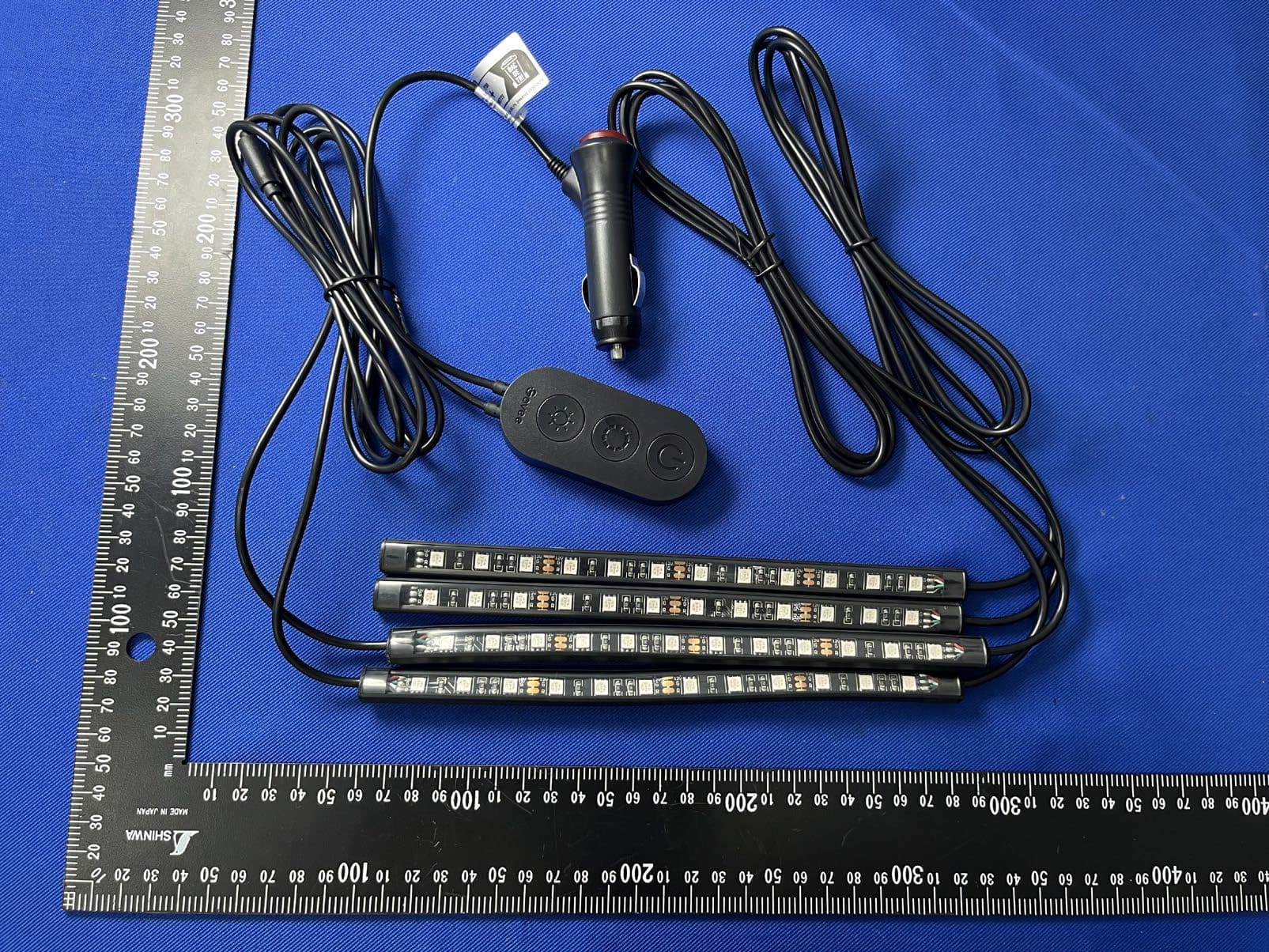
2AQA6-H6114A
Aug 28, 2024Govee RGB Car LED Strip Light
Equipment Class
DTS - Digital Transmission System2AQA6-H604D
Jun 29, 2024Govee DreamView G1S Gaming Light
Equipment Class
DTS - Digital Transmission System
2AQA6-H5085
Nov 13, 2023Smart Plug Pro
Equipment Class
DTS - Digital Transmission System