2AQK4-M3000-AIntelligent Management System
Shenzhen NuboMed Technology Co., Ltd.
Click to zoom
Application Details
- Equipment Class
- DXX - Part 15 Low Power Communication Device Transmitter
- Date of Grant
- May 14, 2023
- Application Purpose
- Original Equipment
- Date of Application
- May 14, 2023
- Equipment Note
- Intelligent Management System
- Frequency Range
- 13.56000000 - 13.56000000
- Country
- China
Documents & Files
Document Text
Text extracted from the exhibit documents filed with the FCC. Open a document above to read the original.
Users Manual
- 1 - Intelligent Management System Product Manuals Updated Date: 2022-09-05 - 2 - Preface Thank you for using NuboMed Intelligent Management System. NuboMed Intelligent Management System is applied to medication management in the operation room pharmacies, which can help the hospital improve management efficiency, streamline medication workflow, reduce the workload, and deliver better patient care. This product manual can be used as reference material for the training and operation of the product. Shenzhen NuboMed Technology Co., Ltd. - 3 - Catalogue 1、 Statements...................................................................................................................... - 4 - 1.1 Important Statements .................................................................................... - 4 - 1.2 Operating Environment ................................................................................. - 4 - 1.3 Configuration ................................................................................................... - 5 - 2、 Product Illustrations .................................................................................................... - 6 - 2.1 Components ..................................................................................................... - 6 - 2.2 Components Illustrations .............................................................................. - 6 - 3、 Frequently Asked Questions .................................................................................... - 7 - 4、 Precautions .................................................................................................................... - 8 - 4.1 Important Notes ................................................................................................... - 8 - 4.2 Previewing .............................................................................................................. - 9 - Cleaning Guidelines ............................................................................................................ - 9 - 5、 Commitment ................................................................................................................. - 9 - - 4 - 1、 Statements 1.1 Important Statements Before the operation, please read the product manual carefully. Special attention should be paid to safety instructions. Failure to follow these instructions may result in device damage or personal injury. 1. The intelligent management system can only be operated by trained staff, following the instructions of this manual. 2. Please maintain the equipment according to the maintenance instructions in this manual. Device maintenance can only be carried out by Shenzhen NuboMed Technology Co., Ltd. or its authorized and designated service personnel. 3. Do not install the device near an electromagnetic interference source. 4. Do not change the software and hardware settings of the device. 5. Shenzhen NuboMed Technology Co., Ltd. reserves the right to make changes in the product design or/and product documentation without notification to its users. 1.2 Operating Environment (1) Operating Temperature: 5∽40°C (2) Operating Humidity: 20∽65% (3) No explosive dangerous medium is allowed on the site. The surrounding medium should not contain gas or conductive medium that corrodes metal and damages insulation. (4) The site should be equipped with protective facilities against rain, snow, wind, sand, and ash. - 5 - 1.3 Configuration Item Qty Unit Main Control Module (Touch Screen; Fingerprint/Face ID/RFID Card Authentication Module; Barcode Scanner) 1 Set Operating System 1 Set Cabinet 1 Set Smart Cabinet Components 1 Set Temperature & Humidity Monitor Modules 1 Set Casters 4 Pic Emergency Lock & Key 1 Set Battery 1 Set Burglar Alarm 1 Set HD Camera & Stand 1 Set Video Recorder (with local network and hard disk) 1 Set UPS 1 Set Smart RFID Medical Kits Box 12 Set Barcode Scanner (Optional) 1 Set Printer & Stand (Optional) 1 Set - 6 - 2、 Product Illustrations 2.1 Components 2.2 Components Illustrations (1) Dimensions: W:800mm x D:611.7mm x H:1932mm (camera stand not included); four omni- directional wheels (2) Main Control Module: HD touch screen with the main control system for the operation of the intelligent management system (3) Fingerprint/Face ID/RFID Card Authentication Module; Barcode Scanner (4) Smart Cabinet Components: one RFID for each unit; automatic identification (5) Temperature & Humidity Monitor Modules: track the temperature and humidity level of the cabinet inside (6) Burglar Alarm: when the cabinet is damaged by external force, the cabinet triggers the alarm. (7) Emergency Access: Under special circumstances such as blackout or breakdown, the emergency lock key can open all the drawers and keep the integrity of the cabinet. - 7 - (8) HD Camera: 360° HD Camera for monitoring 3、 Frequently Asked Questions Category Descriptions Solutions Startup Failure The device and power indicator do not respond. The power cables are not correctly connected. (Check whether the control circuit is disconnected or contacted well) The power strip connected to the device is disconnected. (Replace it with a valid power board or contact O&M electrical engineers for repair. Check whether the power switch is open. The fuse wires of the power go wrong. (Contact the manufacturer or relevant professionals for follow-up maintenance and replacement). The power indicator of the monitor is off, and there is no response on the black screen. The screen is turned off. (Turn on the screen switch after startup.) The DC power supply plug of the screen is loose (reconnect the power plug and make sure it is correctly connected). The signal wire or plug is damaged. (Contact the manufacturer or relevant personnel to follow up the maintenance and treatment) The main cabinet layer breaks down. - 8 - Main Cabinet Errors occur while the main cabinet responds. (Contact the manufacturer or relevant professionals for follow-up…
Text truncated - open the document above for the full version.
External Photos
Reference No.: WTX22X04073953W001 Page 2 of 22 Waltek Testing Group (Shenzhen) Co., Ltd. Http://www.waltek.com.cn EXHIBIT 2 - EUT EXTERNAL PHOTOGRAPHS EUT View 1 EUT View 2 Reference No.: WTX22X04073953W001 Page 3 of 22 Waltek Testing Group (Shenzhen) Co., Ltd. Http://www.waltek.com.cn EUT View 3 EUT View 4 Reference No.: WTX22X04073953W001 Page 4 of 22 Waltek Testing Group (Shenzhen) Co., Ltd. Http://www.waltek.com.cn EUT View 5 EUT View 6 Reference No.: WTX22X04073953W001 Page 5 of 22 Waltek Testing Group (Shenzhen) Co., Ltd. Http://www.waltek.com.cn EUT View 7 EUT View 8
ID Label/Location Info
Reference No.: WTX22X04073953W001 Page 1 of 22 Waltek Testing Group (Shenzhen) Co., Ltd. Http://www.waltek.com.cn ANNEX EXHIBIT 1 - PRODUCT LABELING Proposed FCC ID Label Format Specifications: The label shall be securely affixed to a permanently attached part of the device, in a location where it is visible or easily accessible to the user, and shall not be readily detachable. The label shall be sufficiently durable to remain fully legible and intact on the device in all normal conditions of use throughout the device’s expected lifetime. Proposed Label Location on EUT FCC ID Label Location
Internal Photos
Reference No.: WTX22X04073953W001 Page 6 of 22 Waltek Testing Group (Shenzhen) Co., Ltd. Http://www.waltek.com.cn EXHIBIT 3 - EUT INTERNAL PHOTOGRAPHS EUT Housing and Board View 1 EUT Housing and Board View 2 Reference No.: WTX22X04073953W001 Page 7 of 22 Waltek Testing Group (Shenzhen) Co., Ltd. Http://www.waltek.com.cn EUT Housing and Board View 3 EUT Housing and Board View 4 Reference No.: WTX22X04073953W001 Page 8 of 22 Waltek Testing Group (Shenzhen) Co., Ltd. Http://www.waltek.com.cn Solder Board-Component View 1 Solder Board-Component View 2 Reference No.: WTX22X04073953W001 Page 9 of 22 Waltek Testing Group (Shenzhen) Co., Ltd. Http://www.waltek.com.cn Solder Board-Component View 3 Solder Board-Component View 4 Reference No.: WTX22X04073953W001 Page 10 of 22 Waltek Testing Group (Shenzhen) Co., Ltd. Http://www.waltek.com.cn Solder Board-Component View 5 Solder Board-Component View 6
Internal Photos
Reference No.: WTX22X04073953W001 Page 11 of 22 Waltek Testing Group (Shenzhen) Co., Ltd. Http://www.waltek.com.cn Solder Board-Component View 7 Solder Board-Component View 8 Reference No.: WTX22X04073953W001 Page 12 of 22 Waltek Testing Group (Shenzhen) Co., Ltd. Http://www.waltek.com.cn Solder Board-Component View 9 Solder Board-Component View 10 Reference No.: WTX22X04073953W001 Page 13 of 22 Waltek Testing Group (Shenzhen) Co., Ltd. Http://www.waltek.com.cn Solder Board-Component View 11 Solder Board-Component View 12
Internal Photos
Reference No.: WTX22X04073953W001 Page 14 of 22 Waltek Testing Group (Shenzhen) Co., Ltd. Http://www.waltek.com.cn Solder Board-Component View 13 Solder Board-Component View 14 Reference No.: WTX22X04073953W001 Page 15 of 22 Waltek Testing Group (Shenzhen) Co., Ltd. Http://www.waltek.com.cn Solder Board-Component View 15 Solder Board-Component View 16 Reference No.: WTX22X04073953W001 Page 16 of 22 Waltek Testing Group (Shenzhen) Co., Ltd. Http://www.waltek.com.cn Solder Board-Component View 17 Solder Board-Component View 18
Internal Photos
Reference No.: WTX22X04073953W001 Page 17 of 22 Waltek Testing Group (Shenzhen) Co., Ltd. Http://www.waltek.com.cn Solder Board-Component View 19 Solder Board-Component View 20 Reference No.: WTX22X04073953W001 Page 18 of 22 Waltek Testing Group (Shenzhen) Co., Ltd. Http://www.waltek.com.cn Solder Board-Component View 21 Solder Board-Component View 22 Reference No.: WTX22X04073953W001 Page 19 of 22 Waltek Testing Group (Shenzhen) Co., Ltd. Http://www.waltek.com.cn Solder Board-Component View 23 Solder Board-Component View 24 Reference No.: WTX22X04073953W001 Page 20 of 22 Waltek Testing Group (Shenzhen) Co., Ltd. Http://www.waltek.com.cn Antenna View1 Antenna View2
RF Exposure Info
1. RF Exposure Requirements 1.1 General Information Client Information Applicant: Shenzhen NuboMed Technology Co., Ltd. Address of applicant: Unit 201, Building D, Skyworth Innovation Valley #5, No.1 Tangtou Road, Shiyan Street, Bao'an District, Shenzhen, China. Manufacturer: Shenzhen NuboMed Technology Co., Ltd. Address of manufacturer: Unit 201, Building D, Skyworth Innovation Valley #5, No.1 Tangtou Road, Shiyan Street, Bao'an District, Shenzhen, China. General Description of EUT: Product Name: Intelligent Management System Trade Name: NuboMed Model No.: M3000-A Rated Voltage: AC120V Power Adapter Model: / FCC ID: 2AQK4-M3000-A Equipment Type: Fixed device Technical Characteristics of EUT: Support Standards: NFC Frequency Range: 13.56MHz Max. Field Strength: Type of antenna 1:52.87dBuV/m (at 3m) Type of antenna 2: 72.52dBuV/m (at 3m) Antenna Type: PCB Antenna Antenna Gain 0dBi 1.2 RF Exposure Exemption According to §1.1307(b)(3) and KDB 447498 D04 Interim General RF Exposure Guidance v01, system operating under the provisions of this section shall be operating in a manner that the public is not exposed to radio frequency energy level in excess limit for maximum permissible exposure. Option A: FCC Rule Part 1.1307 (b)(3)(i)(A):The available maximum time-averaged power is no more than 1mW, regardless of separation distance. Option B: FCC Rule Part 1.1307 (b)(3)(i)(B): The available maximum time-averaged power or effective radiated power (ERP), whichever is greater, is less than or equal to the threshold P th (mW) described in the following formula. P th is given by: Option C: FCC Rule Part 1.1307 (b)(3)(i)(C): The minimum separation distance (R in meters) from the body of a nearby person for the frequency (f in MHz) at which the source operates, the ERP (watts) is no more than the calculated value prescribed for that frequency. R must be at least λ/2π, where λ is the free-space operating wavelength in meters. Single RF Sources Subject to Routine Environmental Evaluation RF Source frequency (MHz) Threshold ERP (watts) 0.3-1.34 1,920 R 2 1.34-30 3,450 R 2 /f 2 30-300 3.83 R 2 300-1,500 0.0128 R 2 f 1,500-100,000 19.2R 2 For Multiple RF sources: FCC Rule Part 1.1307(b)(3)(ii): (A) The available maximum time-averaged power of each source is no more than 1 mW and there is a separation distance of two centimeters between any portion of a radiating structure operating and the nearest portion of any other radiating structure in the same device, except if the sum of multiple sources is less than 1 mW during the time-averaging period, in which case they may be treated as a single source (separation is not required). (B) In the case of fixed RF sources operating in the same time-averaging period, or of multiple mobile or portable RF sources within a device operating in the same time averaging period, if the sum of the fractional contributions to the applicable thresholds is less than or equal to 1 as indicated in the following equation. 1.3 Calculated Result Radio Access Technology Prediction Frequency Max. Field Strength Antenna Gain Output Power Tune-Up Power ERP (MHz) (dBuV/m) (dBi) (dBm) (dBm) (dBm) NFC(Type of antenna 1) 13.56 52.87 0 -42.39 -42.00 -44.54 NFC(Type of antenna 2) 13.56 72.52 0 -22.74 -22.00 -24.89 Frequency Option Min. Distance Max. Power Exposure Limit Ratio Result (MHz) (cm) (dBm) (mW) (mW) Pass/Fail 13.56 B 20 -42.00 0.00 27.66 0.01 Pass 13.56 B 20 -22.00 0.01 27.66 0.01 Pass Note: 1. EIRP= E-104.8+20logD; Output Power=EIRP- Antenna Gain; ERP=EIRP-2.15dB 2. Option A, B and C refers as clause 1.2. 3. For option B, Max (time-averaged power, effective radiated power (ERP)) converts to Max. Power. For option C, ERP converts to Max. Power; 4. For option B, P th (mW) converts to Exposure Limit (mW); For option C, ERP (W) converts to Exposure Limit (mW). 5. Ratio= Tune-Up ERP (mW)/ Exposure Limit (mW) Mode for Simultaneous Multi-band Transmission: Radio Access Technology Ratio 1 Ratio 2 Simultaneous Ratio Limit Result Pass/Fail Antenna 1 + Antenna 2 0.01 0.01 0.02 1 Pass Result: Pass
Test Report
©2019 Dongguan Xstra Dynamic Technology Co., Ltd. Dimensions Unit: mm Tolerance: ±0.25mm Maximum Height of Top: 10mm
Test Report
Waltek Testing Group (Shenzhen) Co., Ltd. Http://www.waltek.com.cn Page 1 of 33 TEST REPORT Reference No. .................... : WTX22X04073953W001 FCC ID ................................ : 2AQK4-M3000-A Applicant ........................... : Shenzhen NuboMed Technology Co., Ltd. Address.............................. : Unit 201, Building D, Skyworth Innovation Valley #5, No.1 Tangtou Road, Shiyan Street, Bao'an District, Shenzhen, China. Manufacturer ..................... : The same as Applicant Address.............................. : The same as Applicant Product Name ................... : Intelligent Management System Model No... ......................... : M3000-A Standards .......................... : FCC Part 15.225 Date of Receipt sample .... : 2022-04-19 Date of Test........................ : 2022-04-19 to 2022-11-15 Date of Issue ..................... : 2022-11-15 Test Report Form No. ....... : WTX_Part 15_225W Test Result ......................... : Pass Remarks: The results shown in this test report refer only to the sample(s) tested, this test report cannot be reproduced, except in full, without prior written permission of the company. The report would be invalid without specific stamp of test institute and the signatures of approver. Prepared By: Waltek Testing Group (Shenzhen) Co., Ltd. Address: 1/F., Room 101, Building 1, Hongwei Industrial Park, Liuxian 2nd Road, Block 70 Bao'an District, Shenzhen, Guangdong, China Tel.: +86-755-33663308 Fax.: +86-755-33663309 Email: [email protected] Tested by: Approved by: Mike Shi Silin Chen Reference No.: WTX22X04073953W001 Waltek Testing Group (Shenzhen) Co., Ltd. Http://www.waltek.com.cn Page 2 of 33 TABLE OF CONTENTS 1. GENERAL INFORMATION ....................................................................................................................................4 1.1 PRODUCT DESCRIPTION FOR EQUIPMENT UNDER TEST (EUT) .........................................................................4 1.2 TEST STANDARDS .................................................................................................................................................5 1.3 TEST METHODOLOGY ...........................................................................................................................................5 1.4 TEST FACILITY ......................................................................................................................................................5 1.5 EUT SETUP AND TEST MODE ..............................................................................................................................6 1.6 MEASUREMENT UNCERTAINTY .............................................................................................................................7 1.7 TEST EQUIPMENT LIST AND DETAILS ...................................................................................................................8 2. SUMMARY OF TEST RESULTS ......................................................................................................................... 11 3. ANTENNA REQUIREMENT ................................................................................................................................. 12 3.1 STANDARD APPLICABLE ..................................................................................................................................... 12 3.2 TEST RESULT ...................................................................................................................................................... 12 4. RADIATED EMISSIONS ....................................................................................................................................... 13 4.1 STANDARD APPLICABLE ..................................................................................................................................... 13 4.2 TEST PROCEDURE .............................................................................................................................................. 13 4.3 CORRECTED AMPLITUDE & MARGIN CALCULATION ........................................................................................... 15 4.4 SUMMARY OF TEST RESULTS/PLOTS ................................................................................................................. 16 5. OUT OF BAND EMISSIONS ................................................................................................................................ 21 5.1 STANDARD APPLICABLE ..................................................................................................................................... 21 5.2 TEST PROCEDURE .............................................................................................................................................. 21 5.3 SUMMARY OF TEST RESULTS/PLOTS ................................................................................................................. 21 6. FREQUENCY STABILITY .................................................................................................................................... 24 6.1 STANDARD APPLICABLE ..................................................................................................................................... 24 6.2 TEST PROCEDURE .............................................................................................................................................. 24 6.3 SUMMARY OF TEST RESULTS/PLOTS ................................................................................................................. 24 7. EMISSION BANDWIDTH ...................................................................................................................................... 26 7.1 APPLICABLE STANDARD ..................................................................................................................................... 26 7.2 TEST PROCEDURE ......................…
Text truncated - open the document above for the full version.
Test Setup Photos
Reference No.: WTX22X04073953W001 Page 21 of 22 Waltek Testing Group (Shenzhen) Co., Ltd. Http://www.waltek.com.cn EXHIBIT 4 - TEST SETUP PHOTOGRAPHS Conducted Emission Test Setup Radiation Emission Test Setup (Below 30MHz) Reference No.: WTX22X04073953W001 Page 22 of 22 Waltek Testing Group (Shenzhen) Co., Ltd. Http://www.waltek.com.cn Radiation Emission Test Setup (30MHz to 1GHz) ***** END OF REPORT *****
Contact Information
Applicant
Yuwei Liu(CEO)
Test Firm
Waltek Testing Group (Shenzhen) Co., Ltd.Jandy So
Technical Specifications
| # | Rule Parts | Frequency Range | Power Output |
|---|---|---|---|
| 1 | 15C | 13.56 MHz - 13.56 MHz | - |
Other Applications from Shenzhen NuboMed Technology Co., Ltd.
2AQK4X5000
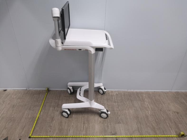
Jan 13, 2020Intelligent Mobile Cart
Equipment Class
DTS - Digital Transmission System