2AQN2-T60RMotorcycle Bluetooth Intercom
Shenzhen winnerelec Industrial CO.,LTD
Click to zoom
Application Details
- Equipment Class
- DSS - Part 15 Spread Spectrum Transmitter
- Date of Grant
- Nov 09, 2022
- Application Purpose
- Original Equipment
- Date of Application
- Nov 09, 2022
- Equipment Note
- Motorcycle Bluetooth Intercom
- Frequency Range
- 2402.00000000 - 2480.00000000
- Country
- China
Documents & Files
Document Text
Text extracted from the exhibit documents filed with the FCC. Open a document above to read the original.
Users Manual
T60R User Manual MOTORCYCLE BLUETOOTH INTERCOM 1 Volume- Earphone port(charing) Volume+ Mesh Intercom button Power button QUICK START GUIDE 2 First fix the screws on the base, insert the installed base into the left side of the helmet, use the socket head cap screws Tighten the screws with the knife, and install the main unit on the base. If there are any problems with mounting tne bracket, you may use the 3M tape bracket.peel off the protective backing sheet of the 3M tape and adhere the bracket onto the helmet.Pressfor15 seconds and glue dry for 24 hours. Tear off the rough surface of the left and right speaker Velcro on the headset, and paste them on the left and right ears of the helmet, then After attaching the speaker to the Velcro surface in the helmet, the speaker with short headphone cable is installed in the left ear. The long horn is mounted on the right ear. Paste the microphone Velcro on the rough surface of the helmet, and then paste the microphone on the on the Velcro. INSTALLATION INSTRUCTIONS Basic Operation TYPE OPERATION BUTTON COMMANDS Power On Power Off Volume Up Volume Down Check the battery Mobile Photo Voice Command (Siri/S-Voice) press for one second press for one second press for 8 second quick press twice Moblle Phone pairing press for 5 second Answer the call short press once End phone call Reject phone call short press once quick press twice quick press twice Answer third party call Reject third party call quick press twice press for one second press for one second Pairing With Phone When the “T60R ”is power off ,hold down the “center key” for 5 seconds.after “T60R”the paring state,the red and blue lights flashing alternately . turn on the bluetooth of the mobile phone ,search for new devices,and select the connection when “T60R”is found. TYPE OPERATION BUTTON COMMANDS Mesh interphone enabled Mesh interphone closed Volume Up Volume Down Reset the MESH Intercom press for 8 seconds While Mesh intercom mode on ,“T60R”will autom atically connect to nearby “T60R” users and allow them to support up to 32 rider onlino at the same time through open intercom free conversation. When the headset Mesh is reset,it clears all network ing informationand automatically returns to the default channel 4. MESH Intercom Moblle Phone Pairing press for 5 seconds short press once short press once short press once short press once 5 TYPE OPERATION BUTTON COMMANDS Setting Frequency Range Enter channel setting surfing the channels Save channel and exit If another team is using channel 4(the default channel)and the network intercom is being interfered with,it can be changed to another channels 1 to 10 Bluetooth Intercom Intercom No1 and No 2 enter into pairing mode quick press twice press for 2 second press for 2 second press for 2 second Short press one of the intercom is “power”key to search short press once Bluetooth Intercom hang up the Bluetooth intercom short press once FM Radio FM Rideo on FM Rideo off press for 2 second press for 2 second Scan up Scan down quick press twice quick press twice press for 2 second 6 TYPE OPERATION BUTTON COMMANDS Intercom No1 and No 2 enter into pairing mode Short press one of the intercom is “power”key to search Bluetooth Intercom hang up the Bluetooth intercom Universal Bluetooth Intercom short press once press for 2 second short press once short press once Music Music play Music pause Last song Next song share the music that is playing short press once short press once quick press twice quick press twice quick press twice Restore factory setting press for 5 seconds power off, clear set Technical specifications Bluetooth suppport:HSP,HFP,A2DP,AVRCP,AGHSP Battery:lithium battery,800mA,3.7v Dimensions:92mm*48mm*26mm Certification:CE/FCC/TELEC/ROHS Charging time:3hours Working time:12-18hours 7 WARRANTY CARD Purchase Date Dealer/retailer Iten No customer Name customer Tel customer E-mail QC QUALIFIED CERTICI Passed 06 Product Failure Description (Please be sure to fill in your related information so that we can better serve you intime) 8 NOTE: This equipment has been tested and found to comply with the limits for a Class B digital device, pursuant to part 15 of the FCC Rules. These limits are designed to provide reasonable protection against harmful interference in a residential installation. This equipment generates uses and can radiate radio frequency energy and, if not installed and used in accordance with the instructions, may cause harmful interference to radio communications. However, there is no guarantee that interference will not occur in a particular installation. If this equipment does cause harmful interference to radio or television reception, which can be determined by turning the equipment off and on, the user is encouraged to try to correct the interference by one or more of the following measures: - Reorient or relocate the receiving antenna. - Increase the separation between the equipment and receiver. -Connect the equipment into an outlet on a circuit different from that to which the receiver is connected. -Consult the dealer or an experienced radio/TV technician for help Changes or modifications not expressly approved by the party responsible for compliance could void the user's authority to operate the equipment. This device complies with Part 15 of the FCC Rules. Operation is subject to the following two conditions: (1) this device may not cause harmful interference, and (2) this device must accept any interference received, including interference that may cause undesired operation. PHXIN
Cover Letter(s)
Agent Authorization Company: Shenzhen winnerelec Industrial CO., LTD Address: 411-416 Room Social security building, Honghua Bei Road, Gongming Street Guangming New District, Shenzhen, China Product Name: Motorcycle Bluetooth Intercom Model Number(s): T60R Product Description: Motorcycle Bluetooth Intercom We authorize MiCOM Labs Inc., 575 Boulder Court, Pleasanton, California 94566, USA, to act on our behalf on all matters concerning the certification of above named equipment. We declare that MiCOM Labs Inc. is allowed to forward all information related to the approval and certification of equipment to the regulatory agencies as required and to discuss any issues concerning the approval application. Any and all acts carried out by MiCOM Labs on our behalf shall have the same effect as acts of our own. Signature: Date: Oct. 11, 2022 Name: Frank Zeng Title: General Manager Company: Shenzhen winnerelec Industrial CO., LTD
External Photos
Report No.: AGC00793220901AP03 Page 1 of 4 EXTERNAL PHOTOS All VIEW OF EUT TOP VIEW OF EUT Report No.: AGC00793220901AP03 Page 2 of 4 BOTTOM VIEW OF EUT FRONT VIEW OF EUT Report No.: AGC00793220901AP03 Page 3 of 4 BACK VIEW OF EUT LEFT VIEW OF EUT Report No.: AGC00793220901AP03 Page 4 of 4 RIGHT VIEW OF EUT ****************************************End of Report****************************************
ID Label/Location Info
FCC ID Label Location 10mm*10mm FCC ID: 2AQN2-T60R
Internal Photos
Report No.: AGC00793220901AP03 Page 1 of 5 INTERNAL PHOTOS OPEN VIEW OF EUT (FIGURE 1) OPEN VIEW OF EUT (FIGURE 2) Report No.: AGC00793220901AP03 Page 2 of 5 VIEW OF BATTERY ANTENNA CLOSE-UP PHOTO-1 BT Antenna Report No.: AGC00793220901AP03 Page 3 of 5 ANTENNA CLOSE-UP PHOTO-2 INTERNAL VIEW OF EUT (FIGURE 1) 2.4G Antenna Report No.: AGC00793220901AP03 Page 4 of 5 INTERNAL VIEW OF EUT (FIGURE 2) INTERNAL VIEW OF EUT (FIGURE 3) FM Antenna Report No.: AGC00793220901AP03 Page 5 of 5 INTERNAL VIEW OF EUT (FIGURE 4) INTERNAL VIEW OF EUT (FIGURE 5) ****************************************End of Report****************************************
RF Exposure Info
RF EXPOSURE EVALUATION 1. PRODUCT INFORMATION Product Description Motorcycle Bluetooth Intercom Test Model T60R FCC ID 2AQN2-T60R 2. EVALUATION METHOD According to 447498 D01 General RF Exposure Guidance v06 The 1-g and 10-g SAR test exclusion thresholds for 100 MHz to 6 GHz at test separation distances ≤ 50 mm are determined by: [(max. power of channel, including tune-up tolerance, mW)/(min. test separation distance, mm)] ·[√f(GHz)] ≤ 3.0 for 1-g SAR and ≤ 7.5 for 10-g extremity SAR. Where f(GHz) is the RF channel transmit frequency in GHz Power and distance are rounded to the nearest mW and mm before calculation 3. CALCULATION BR/EDR: Pt=-2.352dBm=0.582mW The value of the Maximum output power Pt is referred to the test report of the CFR47 §15.247. The result for RF exposure evaluation SAR=(0.582mW /5mm) .[√2.441(GHz)]= 0.18<3.0 for 1-g SAR and ≤ 7.5 for 10-g extremity SAR. 4. CONCLUSION The SAR evaluation is not required.
Test Report
Page 1 of 67 FCC Test Report Report No.: AGC00793220901FE03 FCC ID : 2AQN2-T60R APPLICATION PURPOSE : Original Equipment PRODUCT DESIGNATION : Motorcycle Bluetooth Intercom BRAND NAME : N/A MODEL NAME : T60R APPLICANT : Shenzhen winnerelec Industrial CO., LTD DATE OF ISSUE : Oct. 10, 2022 STANDARD(S) : FCC Part 15.247 REPORT VERSION : V1.0 Attestation of Global Compliance (Shenzhen) Co., Ltd Report No.: AGC00793220901FE03 Page 2 of 67 REPORT REVISE RECORD Report Version Revise Time Issued Date Valid Version Notes V1.0 / Oct. 10, 2022 Valid Initial Release Report No.: AGC00793220901FE03 Page 3 of 67 TABLE OF CONTENTS 1. VERIFICATION OF CONFORMITY .................................................................................................................. 5 2. GENERAL INFORMATION .............................................................................................................................. 6 2.1. PRODUCT DESCRIPTION ........................................................................................................................ 6 2.2. TABLE OF CARRIER FREQUENCYS ....................................................................................................... 6 2.3. RECEIVER INPUT BANDWIDTH .............................................................................................................. 7 2.4. EXAMPLE OF A HOPPING SEQUENCY IN DATA MODE ......................................................................... 7 2.5. EQUALLY AVERAGE USE OF FREQUENCIES AND BEHAVIOUR ......................................................... 7 2.6. RELATED SUBMITTAL(S) / GRANT (S) .................................................................................................... 8 2.7. TEST METHODOLOGY ............................................................................................................................. 8 2.8. SPECIAL ACCESSORIES ......................................................................................................................... 8 2.9. EQUIPMENT MODIFICATIONS ................................................................................................................. 8 2.10. ANTENNA REQUIREMENT..................................................................................................................... 8 3. MEASUREMENT UNCERTAINTY ................................................................................................................... 9 4. DESCRIPTION OF TEST MODES ................................................................................................................. 10 5. SYSTEM TEST CONFIGURATION ................................................................................................................ 11 5.1. CONFIGURATION OF EUT SYSTEM ...................................................................................................... 11 5.2. EQUIPMENT USED IN TESTED SYSTEM .............................................................................................. 11 5.3. SUMMARY OF TEST RESULTS .............................................................................................................. 11 6. TEST FACILITY .............................................................................................................................................. 12 7. PEAK OUTPUT POWER ................................................................................................................................ 13 7.1. MEASUREMENT PROCEDURE ............................................................................................................. 13 7.2. TEST SET-UP (BLOCK DIAGRAM OF CONFIGURATION) .................................................................... 13 7.3. LIMITS AND MEASUREMENT RESULT .................................................................................................. 14 8. 20DB BANDWIDTH ........................................................................................................................................ 19 8.1. MEASUREMENT PROCEDURE ............................................................................................................. 19 8.2. TEST SET-UP (BLOCK DIAGRAM OF CONFIGURATION) .................................................................... 19 8.3. LIMITS AND MEASUREMENT RESULTS ............................................................................................... 20 9. CONDUCTED SPURIOUS EMISSION........................................................................................................... 25 9.1. MEASUREMENT PROCEDURE ............................................................................................................. 25 Report No.: AGC00793220901FE03 Page 4 of 67 9.2. TEST SET-UP (BLOCK DIAGRAM OF CONFIGURATION) .................................................................... 25 9.3. MEASUREMENT EQUIPMENT USED .................................................................................................... 25 9.4. LIMITS AND MEASUREMENT RESULT .................................................................................................. 25 10. RADIATED EMISSION ................................................................................................................................. 46 10.1. MEASUREMENT PROCEDURE ........................................................................................................... 46 10.2. TEST SETUP ......................................................................................................................................... 48 10.3. LIMITS AND MEASUREMENT RESULT ............................................................................................... 49 10.4. TEST RESULT........................................................................................................................................ 49 11. NUMBER OF HOPPING FREQUENCY ............................................................…
Text truncated - open the document above for the full version.
Test Report
Report No.: AGC00793220901FE03 Page 62 of 67 Test_Graph_BR_HOP_ANT1_NA_1Mbps_2441_Number of Busrt Test_Graph_BR_HOP_ANT1_NA_1Mbps_2441_Time per Burst Report No.: AGC00793220901FE03 Page 63 of 67 Test_Graph_BR_HOP_ANT1_NA_1Mbps_2480_Number of Busrt Test_Graph_BR_HOP_ANT1_NA_1Mbps_2480_Time per Burst Report No.: AGC00793220901FE03 Page 64 of 67 13. FREQUENCY SEPARATION 13.1. MEASUREMENT PROCEDURE The EUT shall have its hopping function enabled. Use the following spectrum analyzer settings: 1. Span: Wide enough to capture the peaks of two adjacent channels. 2. RBW: Start with the RBW set to approximately 30% of the channel spacing; adjust as necessary to best identify the center of each individual channel. 3. Video (or average) bandwidth (VBW) ≥ RBW. 4. Sweep: Auto. e) Detector function: Peak. f) Trace: Max hold. g) Allow the trace to stabilize. Use the marker-delta function to determine the separation between the peaks of the adjacent channels. 13.2. TEST SETUP (BLOCK DIAGRAM OF CONFIGURATION) Same as described in section 6.2 13.3. MEASUREMENT EQUIPMENT USED The same as described in section 6.3 13.4. LIMITS AND MEASUREMENT RESULT Test Data of Frequency Separation Test Mode Channel Separation (MHz) Limits Pass or Fail GFSK Hopping 1.001 >= 2/3 -20dB BW Pass Test Graphs of Number of Hopping Frequency Test_Graph_BR_HOP_ANT1_NA_1Mbps_Hopping Separation Note: The GFSK modulation is the worst case and recorded in the report. Report No.: AGC00793220901FE03 Page 65 of 67 14. LINE CONDUCTED EMISSION TEST 14.1. LIMITS OF LINE CONDUCTED EMISSION TEST Frequency Maximum RF Line Voltage Q.P. (dBμV) Average (dBμV) 150kHz~500kHz 66-56 56-46 500kHz~5MHz 56 46 5MHz~30MHz 60 50 Note: 1. The lower limit shall apply at the transition frequency. 2. The limit decreases linearly with the logarithm of the frequency in the range 0.15 MHz to 0.50 MHz. 14.2. BLOCK DIAGRAM OF LINE CONDUCTED EMISSION TEST EUT & Support Units Report No.: AGC00793220901FE03 Page 66 of 67 14.3. PRELIMINARY PROCEDURE OF LINE CONDUCTED EMISSION TEST 1. The equipment was set up as per the test configuration to simulate typical actual usage per the user’s manual. When the EUT is a tabletop system, a wooden table with a height of 0.8 meters is used and is placed on the ground plane as per ANSI C63.10 (see Test Facility for the dimensions of the ground plane used). When the EUT is a floor-standing equipment, it is placed on the ground plane which has a 3-12 mm non-conductive covering to insulate the EUT from the ground plane. 2. Support equipment, if needed, was placed as per ANSI C63.10. 3. All I/O cables were positioned to simulate typical actual usage as per ANSI C63.10. 4. All support equipment received AC120V/60Hz power from a LISN, if any. 5. The EUT received DC 5V power from adapter which received AC120V/60Hz power from a LISN. 6. The test program was started. Emissions were measured on each current carrying line of the EUT using a spectrum Analyzer / Receiver connected to the LISN powering the EUT. The LISN has two monitoring points: Line 1 (Hot Side) and Line 2 (Neutral Side). Two scans were taken: one with Line 1 connected to Analyzer / Receiver and Line 2 connected to a 50 ohm load; the second scan had Line 1 connected to a 50 ohm load and Line 2 connected to the Analyzer / Receiver. 7. Analyzer / Receiver scanned from 150 kHz to 30MHz for emissions in each of the test modes. 8. During the above scans, the emissions were maximized by cable manipulation. 9. The test mode(s) were scanned during the preliminary test. Then, the EUT configuration and cable configuration of the above highest emission level were recorded for reference of final testing. 14.4. FINAL PROCEDURE OF LINE CONDUCTED EMISSION TEST 1. EUT and support equipment was set up on the test bench as per step 2 of the preliminary test. 2. A scan was taken on both power lines, Line 1 and Line 2, recording at least the six highest emissions. Emission frequency and amplitude were recorded into a computer in which correction factors were used to calculate the emission level and compare reading to the applicable limit. If EUT emission level was less – 2dB to the A.V. limit in Peak mode, then the emission signal was re-checked using Q.P and Average detector. 3. The test data of the worst case condition(s) was reported on the Summary Data page. 14.5. TEST RESULT OF LINE CONDUCTED EMISSION TEST N/A Note: The EUT is battery operated without AC mains. Report No.: AGC00793220901FE03 Page 67 of 67 APPENDIX A: PHOTOGRAPHS OF TEST SETUP Refer to the Report No.: AGC00793220901AP02 APPENDIX B: PHOTOGRAPHS OF EUT Refer to the Report No.: AGC00793220901AP03 ----END OF REPORT---- Conditions of Issuance of Test Reports 1. All samples and goods are accepted by the Attestation of Global Compliance (Shenzhen) Co., Ltd. (the “Company”) solely for testing and reporting in accordance with the following terms and conditions. The company provides its services on the basis that such terms and conditions constitute express agreement between the company and any person, firm or company requesting its services (the “Clients”). 2. Any report issued by Company as a result of this application for testing services (the “Report”) shall be issued in confidence to the Clients and the Report will be strictly treated as such by the Company. It may not be reproduced either in its entirety or in part and it may not be used for advertising or other unauthorized purposes without the written consent of the Company. The Clients to whom the Report is issued may, however, show or send it, or a certified copy thereof prepared by the Company to its customer, supplier or other persons directly concerned. The Company will not, without the consent of the Clients, enter into any discussion or correspondence with any third party concerning the contents of the Report, unless required by the relevant governmental authorities, laws or court orders. 3.The Company shall not be called or be liable to be called to give evidence or testimo…
Text truncated - open the document above for the full version.
Test Report
SHENZHEN WINNERELEC INDUSTRIAL CO.,LTD. APPROVALSHEET 1. CUSTOMER. : ___________________ 2. Antenna Model : AT2.4G -PCB 3.Antenna type. : Ceramic Antenna___ 4.APPROVALNO. : AT2.4G-PCB 5. ISSUED DATE. :___________________ APPROVAL BYCHECKED BYPREPARED BY SHENZHEN WINNERELEC INDUSTRIAL CO.,LTD. Application ofAT2.4G-PCB Series 1.Dimensions CUSTOMER’S P/NDRAWING NOAT2.4G-09 PREPARED BYCHECKEDBYAPPROVAL BY S.R.NO DATE: SHENZHEN WINNERELEC INDUSTRIAL CO.,LTD. Electric Specifications TYPEPCB Series Operating Frequency Range2400~2484MHz Input impedance 50Ω Operating VoltageRange3.0V~4.2V Antenna gain0dBi Demodulation Mode GFSK(Basic Data Rate) & 8DPSK(Enhanced Data Rate) 2.4CUSTOMER’S P/N DRAWING NOAT2.4G-PCB Series PREPARED BYCHECKED BYAPPROVAL BY S.R.NO DATE: 2. Radiation Pattern Efficiency Peak Gain Directivity 2450MHz 68.15% 0 dBi 1.15 dB Chamber Coordinate System X Y Z SHENZHEN WINNERELEC INDUSTRIAL CO.,LTD. 3. 8/11 4.Reliability and Test Condictions ITEM REQUIREMENTS TEST CONDITION Solderability 1.Wetting shall exceed 90% coverage 2. No visible mechanical damage Pre-heating temperature:150°C/60sec. Solder temperature:230±5°C Duration:4±1sec. Solder:Sn-Ag3.0-Cu0.5 Flux for lead free: rosin Solder heat Resistance 1. No visible mechanical damage 2.Central Freq. change :within ± 6% 10±0.5 sec. 60sec .. TEMP (°C) 150°C 260°C Pre-heating temperature:150°C/60sec. Solder temperature:260±5°C Duration:10±0.5sec. Solder:Sn-Ag3.0-Cu0.5 Flux for lead free: rosin Component Adhesion (Push test) 1. No visible mechanical damage The device should be reflow soldered(230±5°C for 10sec.) to a tinned copper substrate A dynometer force gauge should be applied the side of the component. The device must with-ST-F 0.5 Kg without failure of the termination attached to component. Component Adhesion (Pull test) 1. No visible mechanical damage Insert 10cm wire into the remaining open eye bend ,the ends of even wire lengths upward and wind together. Terminal shall not be remarkably damaged. Thermal shock 1. No visible mechanical damage 2.Central Freq. change :within ±6% Phase Temperature(°C) Time(min) 1 +85±5°C 30±3 2 Room Temperature Within 3sec 3 -40±2°C 30±3 4 Room Temperature Within 3sec +85°C=>30±3min -40°C=>30±3min Test cycle:10 cycles The chip shall be stabilized at normal condition for 2~3 hours before measuring. Resistance to High Temperature 1. No visible mechanical damage 2. Central Freq. change :within ±6% 3.No disconnection or short circuit. Temperature: 85±5°C Duration: 1000±12hrs The chip shall be stabilized at normal condition for 2~3 hours before measuring. Resistance to Low Temperature 1. No visible mechanical damage 2. Central Freq. change :within ±6% 3.No disconnection or short circuit. Temperature:-40±5°C Duration: 1000±12hrs The chip shall be stabilized at normal condition for 2~3 hours before measuring. Humidity 1. No visible mechanical damage 2. Central Freq. change :within ±6% 3.No disconnection or short circuit. Temperature: 40±2°C Humidity: 90% to 95% RH Duration: 1000±12hrs The chip shall be stabilized at normal condition for 2~3 hours before measuring. 4±1 sec. 60sec TEMP (°C) 150°C 230°C SHENZHEN WINNERELEC INDUSTRIAL CO.,LTD. 5.Soldering and Mounting Mildly activated rosin fluxes are preferred. The minimum amount of solder can lead to damage from the stresses caused by the difference in coefficients of expansion between solder, chip and substrate. The terminations are suitable for all wave and re-flow soldering systems. If hand soldering cannot be avoided, the preferred technique is the utilization of hot air soldering tools. Recommended temperature profiles for re-flow soldering in Figure 1. Products attachment with a soldering iron is discouraged due to the inherent process control limitations. In the event that a soldering iron must be employed the following precautions are recommended. ‧Preheat circuit and products to 150°C ‧Never contact the ceramic with the iron tip ‧Use a 20 watt soldering iron with tip diameter of 1.0mm ‧280°C tip temperature (max) ‧1.0mm tip diameter (max) ‧Limit soldering time to 3 sec. SOLDERING COOLING NATURAL PRE-HEATING TEMPERATURE(°C) 60~120 s 10s max. 30~60s 250~260 230 180 150 TIME(sec.) Reflow Soldering SOLDERING COOLING NATURAL PRE-HEATING TEMPERATURE(°C) within 3s Gradual cooling 150 TIME(sec.) Iron Soldering Over 60s 350 300 SHENZHEN WINNERELEC INDUSTRIAL CO.,LTD. ONEWAVE TECHNOLOGY CO., LTD. Packaging Information Tape Specification: Reel Specification: (7’’, Φ180 mm) Tape Width(mm) A(mm) B(mm) C(mm) D(mm) Chip/Reel(pcs) 8 9.0±0.5 60±2 13.5±0.5 178±2 3000 SHENZHEN WINNERELEC INDUSTRIAL CO.,LTD. 6. Storage and Transportation Information Storage Conditions To maintain the solderability of terminal electrodes: 1. Temperature and humidity conditions: -10~ 40°C and 30~70% RH. 2. Recommended products should be used within 6 months from the time of delivery. 3. The packaging material should be kept where no chlorine or sulfur exists in the air. Transportation Conditions 1. Products should be handled with care to avoid damage or contamination from perspiration and skin oils. 2. The use of tweezers or vacuum pick up is strongly recommended for individual components. 3. Bulk handling should ensure that abrasion and mechanical shock are minimized. SHENZHEN WINNERELEC INDUSTRIAL CO.,LTD. 7.
Test Setup Photos
Report No.: AGC00793220901AP02 Page 1 of 2 TEST SETUP PHOTOS RADIATED EMISSION TEST SETUP BELOW 1GHz RADIATED EMISSION TEST SETUP ABOVE 1GHz Report No.: AGC00793220901AP02 Page 2 of 2 RF CONDUCTED TEST SETUP-BT RF CONDUCTED TEST SETUP-2.4G ****************************************End of Report*************************************
Contact Information
Applicant
Frank Zeng
Technical Contact
Test Firm
Attestation of Global Compliance (Shenzhen) Co., LDoris Li
[email protected]+86-755-25234088
Technical Specifications
| # | Rule Parts | Frequency Range | Power Output |
|---|---|---|---|
| 1 | 15C | 2.40 GHz - 2.48 GHz | 600.00 µW |
Other Applications from Shenzhen winnerelec Industrial CO.,LTD
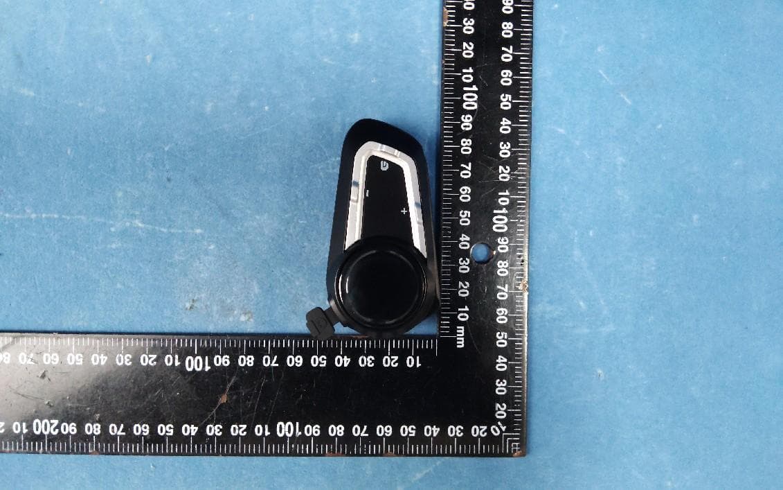
2AQN2-V10S
Sep 03, 2024Motorcycle Bluetooth intercom
Equipment Class
DSS - Part 15 Spread Spectrum Transmitter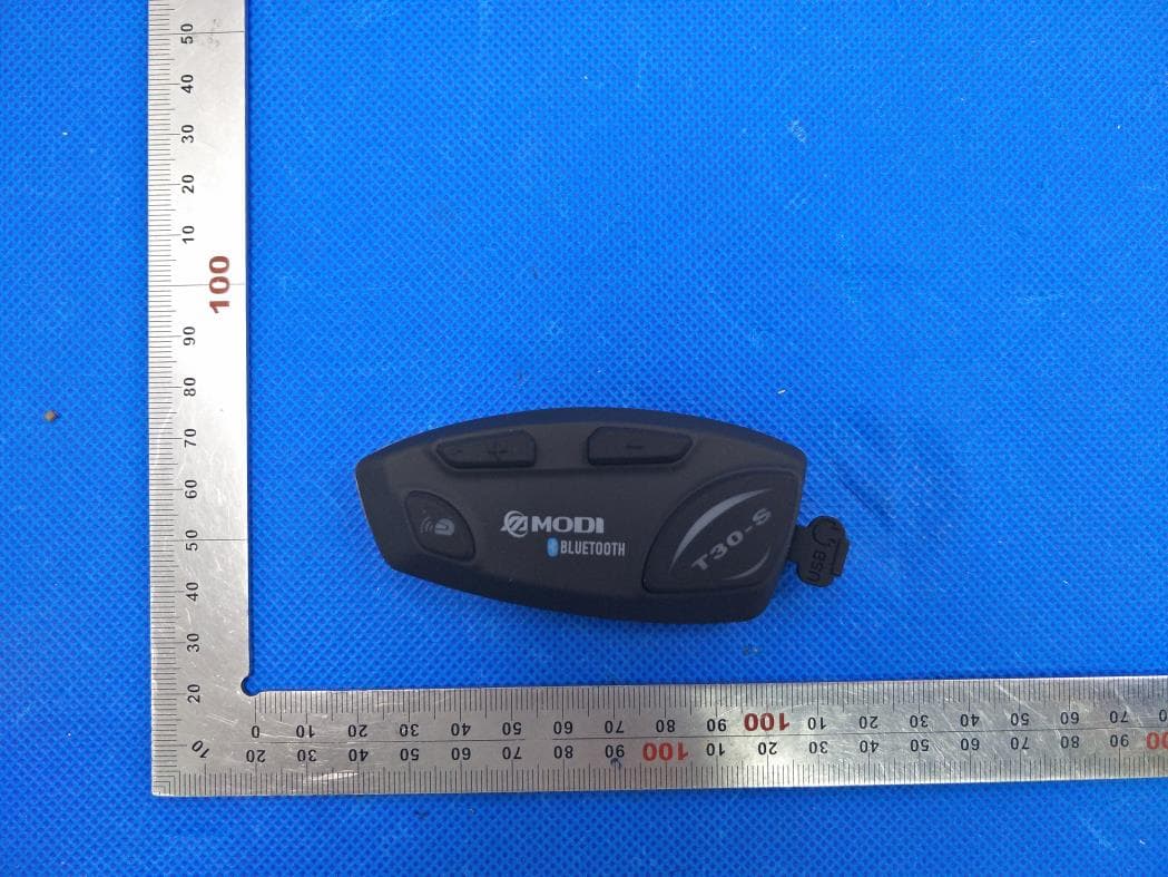
2AQN2-T30-S
Jun 07, 2020Motorcycle 4-Way Conference Intercom
Equipment Class
DSS - Part 15 Spread Spectrum Transmitter