2AQQMJTROBOTIIBSorting Robot
Zhejiang Libiao Robotics Co., Ltd.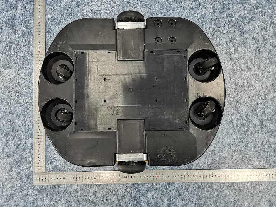
Click to zoom
Application Details
- Equipment Class
- DXX - Part 15 Low Power Communication Device Transmitter
- Date of Grant
- Dec 17, 2020
- Application Purpose
- Original Equipment
- Date of Application
- Dec 17, 2020
- Equipment Note
- Sorting Robot
- Frequency Range
- 904.25000000 - 926.25000000
- Country
- China
Documents & Files
Document Text
Text extracted from the exhibit documents filed with the FCC. Open a document above to read the original.
Users Manual
User Manual of JTRobotIIB Sorting Robot 1. Brief Descriptions JTRobotIIB sorting robot are mainly used for sorting in industries of express delivery services and warehousing logistics. Operated on special sorting platforms, these robots can receive and execute orders from servers to unload parcels and transport them to designated locations. Product pictures: 2.Descriptions of Product Modules 2.1.BMSP module 2.1.1.BMSPmodule through the chas sis module read RFID(13.56MHz) tags, get the current location information, robot and wireless module to the server, the server based on the current robot position and state issued work instructions, robot analy tic server command, and control the servo device, such as complete instruction execution, so as to realize the robot control and turning control, version control, movement, finally realizes the whole working process. 2.1.2.Power management module In the power management module, commands for powering on and off robots can be obtained through wireless module. If a command for powering on robot is received, the power management module will switc h on the power supply and power on all devices. When a command for powering off robot is received, the module will switch off the power supply and power off all devices. Meanwhile, all other devices will be switched to standby states with low power consumption except for the power management module. 2. 2. Chassis module Realize the detection of RFID(13.56MHz) code and location information detection, and upload. The data to the BMSP module through CAN communication. 2. 3. Switching power module Voltage conversion from 4.6V to 24V is under the control of the power managementmodule. 2.4. Battery Pack and Charging Port The battery pack is made of two 2.3V lithium batteries connected in series. The robot must be charged using special charging piles. The maximum charging current is 90A. 2.5. Servo Modules At present, a robot has three servo modules, including left wheel, right wheel and lift , which are used for controlling walking and Unloading control 2.6. RADAR Device The radar is responsible for avoiding obstacles, and the robot with obstacles triggers the parking. 2.7. Buttons and LED Indicator Lights Buttons are utilized for testing single robots and manually controlling shutdown. The LED indicator light is employed for indicating current state. The functions of buttons and the indicator lights are shown as follows: T he bright red LED indicator lights can indicate malfunctions. The states of the indicator lights are shown as follows: SN State of Indicator Light Descriptions of State Operation State Standby 1 off off off Batteries are disconnected or power is not supplied. 2 off off on for 0.2s and off for 4s Standby 3 on for 0.5s and off for 1.5s off off Under the state of shutdown, orders from the server are not executed, and no malfunction is reported under this state. 4 on for 0.5s and off for 0.5s off off Under operation, receiving commands from the server 5 on for 0.5s and off for on off Under operation, waiting for commands from the server 0.5s 6 on for 0.2s and off for 0.2s on for 0.2s and off for 0.2s on for 0.2s and off for 0.2s Malfunctioning, generally because RFID can’t be recognized. 7 Any light is always on Enter the function mode. 8 Any light is on for 0.2s and off 0.2s Mode of function selection An Introduction to Functions of Buttons: No button will function when a robot is under the No.1 State shown on the above table. Oper ation State Standby Operation Shutdown Function Current State No. (see above table) ) Buttons Description of Functions 1 Any No function 2 Press [A] + [C] for 3s Power on and wake the robot up 3- 8 Press [B] + [C] for 5s Power off and switch the robot to a standby state 3-6 Press [A] The robot enters the operation state 3-6 Press [B] The robot enters the shutdown state 3- 6 Press [C] Enter the state of function selection (No.8 state). Later, you can switch to another function once you press [C] and choose any one from No.1 to No.7 functions 8 Press [A] Enter the state of current function (No.7 State) 8 Press [B] Exit from the state of function selection and return to the state of shutdown 7 Press [A] Start executing the current function 7 Press [B] Suspend the execution of the current function 7 Press [C] Exit from the current function and return to the state of shutdown Notes: All above operations are manual manipulations of a single robot for maintenance or testing. No manipulation will be needed when a robot is under normal operation. 3.User Instructions Robots are actuators of sorting systems and their normal operations require the support of the whole sorting platform. During their normal work, no manipulation is needed at all, and all of their operations are completed on the server. 3.1. Powering on Robots are powered on with server software and switching devices. You can send a command for powering on a robot with switching software of the server through the LBAP-102LU wireless device of the switching device. Then, the robot can be automatically powered on. 3.2. Sorting Robot sorting can be realized through the server. You can control the robots and exchange data via wireless module with server software. The server will try connecting all robots which have been powered on. After normal connection, the server will keep being connected with the robots, acquire information about robots’ current position via RFID codes and control robots’ walking or Liftingaccording to state of current sorting platform. 3.3. Pow ering off Robots are powered off with server software and switching devices. The robots can be powered off by issuing corresponding commands to them through the LBAP- 102LU wireless device of the switching device with switching software of the server. The robot will automatically shut down when it detects that the battery voltage is lower than 3.8V. FCC Statement Any Changes or modifications not expressly approved by the party responsible for compliance cou…
Text truncated - open the document above for the full version.
Cover Letter(s)
Company: Zhejiang Libiao Robotics Co., Ltd. Add: Room 603, South Building No. 2, Chaofeng East Road, Yuhang Economic Development District, Hangzhou, Zhejiang, China Tel: (86) 5 71-85857789 Fax: (86) 571-85857619 FCC Authorization Date: 2020-10-13 FEDERAL COMMUNICATIONS COMMISSION Authorization and Evaluation Division 7435 Oakland Mills Road Columbia, MD 21046 Subject: Agent Authorization To whom it may concern: We, Zhejiang Libiao Robotics Co., Ltd., the undersigned, Hereby authorizes Bay Area Compliance Laboratories Corporation to act on its behalf in all matters relating to application for Equipment authorization, including the signing of all documents relating to these matters. All acts carried out by Bay Area Compliance Laboratories Corp. on our behalf shall have the same effect as our own action. We, the undersigned, hereby certify that we are not subject to a denial of federal benefits, that includes FCC benefits, pursuant to Section 5301 of the Anti-Drug Abuse Act of 1988, 21 U.S.C. 862. This authorization is valid until further written notice from the applicant. Sincerely Yours, Signature: Printed Name: JueJing Xu Title: R&D Manager QA-FR-170-B
Cover Letter(s)
Company: Zhejiang Libiao Robotics Co., Ltd. Add: Room 603, South Building No. 2, Chaofeng East R oad, Yuhang Economic Development District, Hangzhou, Zhejiang, China Tel: (86) 571-85857789 Fax: (86) 571-85857619 E-mail: [email protected] FCC Confidential Authorization Date: 2020-10-13 FEDERAL COMMUNICATIONS COMMISSIONS Authorization and Evaluation Division 7435 Oakland Mills Road Columbia, MD 21046 Subject: Confidentiality Request regarding application for certification of FCC ID:2AQQMJTROBOTIIB To: whom it may concern, In accordance with Sections 0.457 and 0.459 of the Commission’s Rules, Zhejiang Libiao Robotics Co., Ltd. hereby requests long-term confidential treatment of information accompanyi ng this application as outlined below: Block Diagram Schematics Operation Description The above materials contain proprietary and confidential information not customarily released to the public. The public disclosure of these materials provides unjustified benefits to its competitors in the market. Sincerely Yours, Signature: Printed Name: JueJing Xu Title: R&D Manager
External Photos
EXHIBIT A - EUT EXTERNAL PHOTOGRAPHS EUT: JTRobotIIB Charging pile : LBPower5330 A
ID Label/Location Info
1
Internal Photos
EXHIBIT B - EUT INTERNAL PHOTOGRAPHS RFID Antenna 13.56MHz chip:MFRC522 SRD Antenna
Test Report
FCC PART 15.225 TEST REPORT For Zhejiang Libiao Robotics Co., Ltd. Room 603, South Building No. 2, Chaofeng East Road, Yuhang Economic Development District, Hangzhou, Zhejiang, China FCC ID: 2AQQMJTROBOTIIB Report Type: Original Report Product Type: Sorting Robot Project Engineer: Chao Gao Report Number: RSHA201013001-00B Report Date: 2020-12-02 Reviewed By: Oscar Ye EMC Manager Prepared By: Bay Area Compliance Laboratories Corp. (Kunshan) No.248 Chenghu Road,Kunshan,Jiangsu province,China Tel: +86-0512-86175000 Fax: +86-0512-88934268 www.baclcorp.com.cn Bay Area Compliance Laboratories Corp. (Kunshan) Report No.: RSHA201013001-00B TABLE OF CONTENTS GENERAL INFORMATION ....................................................................................................................................... 3 PRODUCT DESCRIPTION FOR EQUIPMENT UNDER TEST (EUT) ..................................................................................... 3 OBJECTIVE ................................................................................................................................................................... 3 RELATED SUBMITTAL(S)/GRANT(S) ............................................................................................................................. 3 TEST METHODOLOGY .................................................................................................................................................. 3 MEASUREMENT UNCERTAINTY .................................................................................................................................... 4 TEST FACILITY ............................................................................................................................................................. 4 SYSTEM TEST CONFIGURATION .......................................................................................................................... 5 JUSTIFICATION ............................................................................................................................................................. 5 EUT EXERCISE SOFTWARE .......................................................................................................................................... 5 EQUIPMENT MODIFICATIONS ....................................................................................................................................... 5 SUPPORT EQUIPMENT LIST AND DETAILS .................................................................................................................... 5 EXTERNAL I/O CABLE .................................................................................................................................................. 5 BLOCK DIAGRAM OF TEST SETUP ................................................................................................................................ 6 SUMMARY OF TEST RESULTS ............................................................................................................................... 7 TEST EQUIPMENT LIST ........................................................................................................................................... 8 FCC§15.203 - ANTENNA REQUIREMENT .............................................................................................................. 9 APPLICABLE STANDARD .............................................................................................................................................. 9 ANTENNA CONNECTED CONSTRUCTION ...................................................................................................................... 9 FCC §15.207 (A) – AC LINE CONDUCTED EMISSIONS .................................................................................... 10 APPLICABLE STANDARD ............................................................................................................................................ 10 EUT SETUP ................................................................................................................................................................ 10 EMI TEST RECEIVER SETUP ....................................................................................................................................... 10 TEST PROCEDURE ...................................................................................................................................................... 10 FACTOR & OVER LIMIT CALCULATION ...................................................................................................................... 11 TEST RESULTS SUMMARY .......................................................................................................................................... 11 TEST DATA ................................................................................................................................................................ 11 FCC§15.225, §15.205 & §15.209 - RADIATED EMISSIONS TEST ...................................................................... 14 APPLICABLE STANDARD ............................................................................................................................................ 14 EUT SETUP ................................................................................................................................................................ 14 EMI TEST RECEIVER SETUP ....................................................................................................................................... 15 CORRECTED AMPLITUDE & MARGIN CALCULATION ................................................................................................. 15 TEST RESULTS SUMMARY .......................................................................................................................................... 15 TEST DATA .............................................................…
Text truncated - open the document above for the full version.
Test Report
FCC PART 15.249 TEST REPORT For Zhejiang Libiao Robotics Co., Ltd. Room 603, South Building No. 2, Chaofeng East Road, Yuhang Economic Development District, Hangzhou, Zhejiang, China Report Type: Original Report Product Type: Sorting Robot Project Engineer: Chao Gao Report Number: RSHA201013001-00C Report Date: 2020-12-02 Reviewed By: Oscar Ye EMC Manager Test Laboratory: Bay Area Compliance Laboratories Corp. (Kunshan) No.248 Chenghu Road, Kunshan, Jiangsu province, China Tel: +86-0512-86175000 Fax: +86-0 512-88934268 www.baclcorp.com.cn FCC ID: 2AQQMJTROBOTIIB Bay Area Compliance Laboratories Corp. (Kunshan) Report No.: RSHA201013001-00C TABLE OF CONTENTS GENERAL INFORMATION ....................................................................................................................................... 3 PRODUCT DESCRIPTION FOR EQUIPMENT UNDER TEST (EUT) ..................................................................................... 3 OBJECTIVE ................................................................................................................................................................... 3 RELATED SUBMITTAL(S)/GRANT(S) ............................................................................................................................. 3 TEST METHODOLOGY .................................................................................................................................................. 3 MEASUREMENT UNCERTAINTY .................................................................................................................................... 4 TEST FACILITY ............................................................................................................................................................. 4 SYSTEM TEST CONFIGURATION .......................................................................................................................... 5 JUSTIFICATION ............................................................................................................................................................. 5 EUT EXERCISE SOFTWARE .......................................................................................................................................... 6 SUPPORT EQUIPMENT LIST AND DETAILS .................................................................................................................... 6 EXTERNAL I/O CABLE .................................................................................................................................................. 6 BLOCK DIAGRAM OF TEST SETUP ................................................................................................................................ 7 SUMMARY OF TEST RESULTS ............................................................................................................................... 8 TEST EQUIPMENT LIST ........................................................................................................................................... 9 FCC§15.203 - ANTENNA REQUIREMENT ............................................................................................................ 10 APPLICABLE STANDARD ............................................................................................................................................ 10 ANTENNA CONNECTOR CONSTRUCTION .................................................................................................................... 10 FCC §15.207 (A) – AC LINE CONDUCTED EMISSIONS .................................................................................... 11 APPLICABLE STANDARD ............................................................................................................................................ 11 EUT SETUP ................................................................................................................................................................ 11 EMI TEST RECEIVER SETUP ....................................................................................................................................... 11 TEST PROCEDURE ...................................................................................................................................................... 11 FACTOR & OVER LIMIT CALCULATION ...................................................................................................................... 12 TEST RESULTS SUMMARY .......................................................................................................................................... 12 TEST DATA ................................................................................................................................................................ 12 FCC§15.205, §15.209&§15.249- RADIATED EMISSIONS & OUT OF BAND EMISSION .............................. 15 APPLICABLE STANDARD ............................................................................................................................................ 15 EUT SETUP ................................................................................................................................................................ 15 TEST EQUIPMENT SETUP ............................................................................................................................................ 16 TEST PROCEDURE ...................................................................................................................................................... 16 CORRECTED AMPLITUDE & MARGIN CALCULATION ................................................................................................. 17 TEST RESULTS SUMMARY .......................................................................................................................................... 17 TEST DATA ........................................................................…
Text truncated - open the document above for the full version.
Test Setup Photos
EXHIBIT C - TEST SETUP PHOTOGRAPHS Conducted Emissions - Front Side Conducted Emissions - Rear Side Radiated Emissions (Below 30MHz) Radiated Emissions (30MHz~ 1GHz)
Test Setup Photos
EXHIBIT C - TEST SETUP PHOTOGRAPHS Conducted Emissions (Front View) Conducted Emissions (Side View) Radiated Emissions (Below 1GHz) Radiated Emissions (Above 1GHz)
Contact Information
Applicant
JueJing Xu(R&D Manager)
Test Firm
Bay Area Compliance Laboratories Corp. (Kunshan)Mr. John Chan
[email protected]+86 0512 86175000
Technical Specifications
| # | Rule Parts | Frequency Range | Power Output |
|---|---|---|---|
| 2 | 15C | 904.25 MHz - 926.25 MHz | - |
Other Applications from Zhejiang Libiao Robotics Co., Ltd.

2AQQMLBCRB30
Jul 08, 2020Crossbelt Robot
Equipment Class
DXX - Part 15 Low Power Communication Device Transmitter