2AQX5KD-C888two way radio
QUANZHOU KAILI ELECTRONICS CO., LTD.
Click to zoom
Application Details
- Equipment Class
- FRF - Part 95 Family Radio Face Held Transmitter
- Date of Grant
- Dec 02, 2020
- Application Purpose
- Original Equipment
- Date of Application
- Dec 02, 2020
- Equipment Note
- two way radio
- Frequency Range
- 467.56250000 - 467.71250000
- Country
- China
Documents & Files
Document Text
Text extracted from the exhibit documents filed with the FCC. Open a document above to read the original.
Users Manual
Emergency Alarm When“Side Key 2” in the software is programmed to the alarm function,press 【DOWN】 key to alarm; Press PTT key to exit. Charging the BatteryBASIC OPERATION Power Switch(Volume Knob) Turn the power switch to turn on/off the power. When power-on,turn the volume knob to adjust the volume. Channel Selection Turn the channel knob to adjust the channels. PTT Press this button whenever you wish to talk with the user of the other radio. Monitoring Press 【UP】 key to enter into the monitor mode, release it to exit. Scanning It is convenient for the user to search for calls from other channels.When“Side Key 2” in the software is programmed to the scanning function,press 【DOWN】 key to enter into the scanning mode,the transceiver will start to scan with the current channel;Operate it again to exit. UHF Super Receiving Scanning VOX Alarm Function Chinese/English Voice Prompt Wide/Narrow Band Selection High-Low Power Selection Busy Channel Lockout Low Battery Warning 50 CTCSS/208 DCS 1.T he battery is not charged in the factory,please charge the battery under the environmental temperature 5—40°C before using. 2.After purchasing or long-term storage(more than two months), charging the battery for the first time can not reach its saturation capacity,repeat charge/discharge for twice or three times to make battery capacity achieve the best state. 3.Before charging,please power off the transceiver,using the transceiver during charging may affect correct charging. 4.If the battery has been charged fully,please do not charge it again,otherwise the service life of the battery may be shorten or may be damaged. 5.If the service time is significantly reduced even after completely correct charging,the battery can not be used any more,please replace a new battery. MIC Technical Parameters SPECIFICATIONS TRANSMITTER RECEIVER BASIC OPERATIONBASIC OPERATION High-Low Power The transceiver has a high-low power selection, it can be programmed. Busy Channel Lockout The function can prevent interference from other transceivers using the same channel. Battery Power Saving If there is no signal or operation,the radio will reduce its power consumption.The battery power-saving function activates when the channel is unoccupied or has not been in operation. Chinese/English Voice Prompt The transceiver has a manual switching function between the Chinese and the English.Switch to Channel 16,turn off the transceiver,then press 【UP】 key and meanwhile turn on the transceiver to switch between the Chinese and English. VOX This function can be voice activated so the user doesn' t have to press the PTT key. Switch to Channel 7,turn off the transceiver,then press the 【UP】 key and turn on the transceiver at the same time to switch between the ON and OFF of the VOX function. VOX gain inversion level refers to the voice sensitivity, it has level 1-9! Low Battery Warning If the battery power falls to the predetermined value during transmission,the transceiver will give out a voice prompt, please charge in time. Time Out Timer(TOT) The purpose of the TOT is to prevent any single person from using a channel for an extended period of time.An alarm will sound if the transmission continues beyond the set time.The transceiver will stop transmission if this occurs.To stop the alarm,release the PTT key and the transceiver will return to standby. CTCSS/DCS The transceiver has 50 CTCSS and 208 DCS, also non-standard subaudio can be programmed! Special Signaling Special Signaling refers to the CDCSS on the channels is special processed codes.Only when the transceivers in the same company are programmed the same frequency point with the same CDCSS and meanwhile special signaling is programmed,then they can talk to each other. Frequency Range Supply Power Memory Channel Antenna Configuration Work Mode Ground Method Dimension Output Power Modulation Mode Max.Frequency Deviation Sparious Radiation Preemphasis Character Emission Current Sensitivity Audio Power Audio Distortion Intermodulation InterferenceResistance Receiving Current Standby Current DC3.7V 22 Internal Antenna Co/Differ-frequency Simplex Communication Cathode 122*58.5*33.2mm 2W/0.5W FM(F3E) ≤2.5KHz ≤7.5μW Per Octave 6dB ≤1000mA <0.16μV(12dB SINAD) ≥300mW <5% ≥60dB ≤300mA ≤20mA ▲We May Change The Specifications For Technical Improvement Without Prior Notice. 462.5500-462.7250MHz 467.5625-467.7125MHz FCC Statement: Any Changes or modifications not expressly approved by the party responsible for compliance could void the user's authority to operate the equipment. This device complies with part 15 of the FCC Rules. Operation is subject to the following two conditions: (1) This device may not cause harmful interference, and (2) This device must accept any interference received, including interference that may cause undesired operation. ISED RSS Warning: This device complies with Innovation, Science and Economic Development Canada licence-exempt RSS standard(s). Operation is subject to the following two conditions: (1) this device may not cause interference, and (2) this device must accept any interference, including interference that may cause undesired operation of the device. Le présent appareil est conforme aux CNR d'ISED applicables aux appareils radio exempts de licence. L'exploitation est autorisée aux deux conditions suivantes: (1) l'appareil ne doit pas produire de brouillage, et (2) l'utilisateur de l'appareil doit accepter tout brouillage radioélectrique subi, même si le brouillage est susceptible d'en compromettre le fonctionnement. RF Exposure Information (FCC SAR) : RF Exposure Information (SAR) : The SAR limit of USA (FCC) is 1.6W/Kg averaged over one gram of tissue. Product Type: two way radio, model number: KD-C888Pro (FCC ID: 2AQX5KD-C888) has also been tested against this SAR limit. The device was test for typical body-worn operations and head face up operations keep the Tracker at least 25mm from the face.when worn on body must be correct back clip for this produ…
Text truncated - open the document above for the full version.
Cover Letter(s)
QA-FR-170-B Company: QUANZHOU KAILI ELECTRONICS CO., LTD. Ad d : Kaili Electronic Industrial Park(Photoelectric Information Base), Xiamei Town, Nanan, Quanzhou City, Fujian Province, China T el: +86-595-26666977 Fax: +86-595-26666979 E-mail: [email protected] FCC Authori zation Date: 2020-08-17 FEDERAL COMMUNICATIONS COMMISSION Authorization and Evaluation Division 7435 Oakland Mills Road Columbia, MD 21046 Subject: Agent Authorization To whom i t may concern: We, QUANZHOU KAILI ELECTRONICS CO., LTD., hereby authorizes Bay Area Compliance Laboratories Corporation to act on its behalf in all matters relating to application for Equipment authorization, including the signing of all documents relating to these matters. All acts carried out by Bay Area Compliance Laboratories Corp. on our b ehalf shall have the same effect as our own action. We, the undersigned, hereby certify that we are not subject to a denial of federal benefits, that includes FCC benefits, pursuant to Section 5301 of the Anti-Drug Abuse Act of 1988, 21 U.S.C. 862. This a uthorization is valid until further written notice from the applicant. Sincer ely Yours, Signature: Typed or Printed Name: Jacky Wang Title: Manager
Cover Letter(s)
QA-FR-171-A Company: QUANZHOU KAILI ELECTRONICS CO., LTD. Add: Kaili Electronic Industrial Park(Photoelectric Information Base), Xiamei Town, Nanan, Quanzhou City, Fujian Province, China Tel: +86-595-26666977 Fax: +86-595-26666979 E-mail: [email protected] FCC Confidenti al Authorization 2020-08-17 FEDERAL COMM UNICATIONS COMMISSIONS Authorization and Evaluation Division 7435 Oakland Mills Road Columbia, MD 21046 Subject: Confidentiality Request regarding application for certification of FCC ID: 2AQX5KD-C888 In accordance with Sections 0.457 and 0.459 of the Commission’s Rules, QUANZHOU KAILI ELECTRONICS CO., LTD., hereby requests long-term confidential treatment of information accompanying this application as outlined below: •Block Diagram •Schematics •Operation Description The above materials contain proprietary and confidential information not customarily released to the public. The public disclosure of these materials provides unjustified benefits to its competitors in the market. Sincerely, Signature: Typed or Printed Name: Jacky Wang Title: Manager
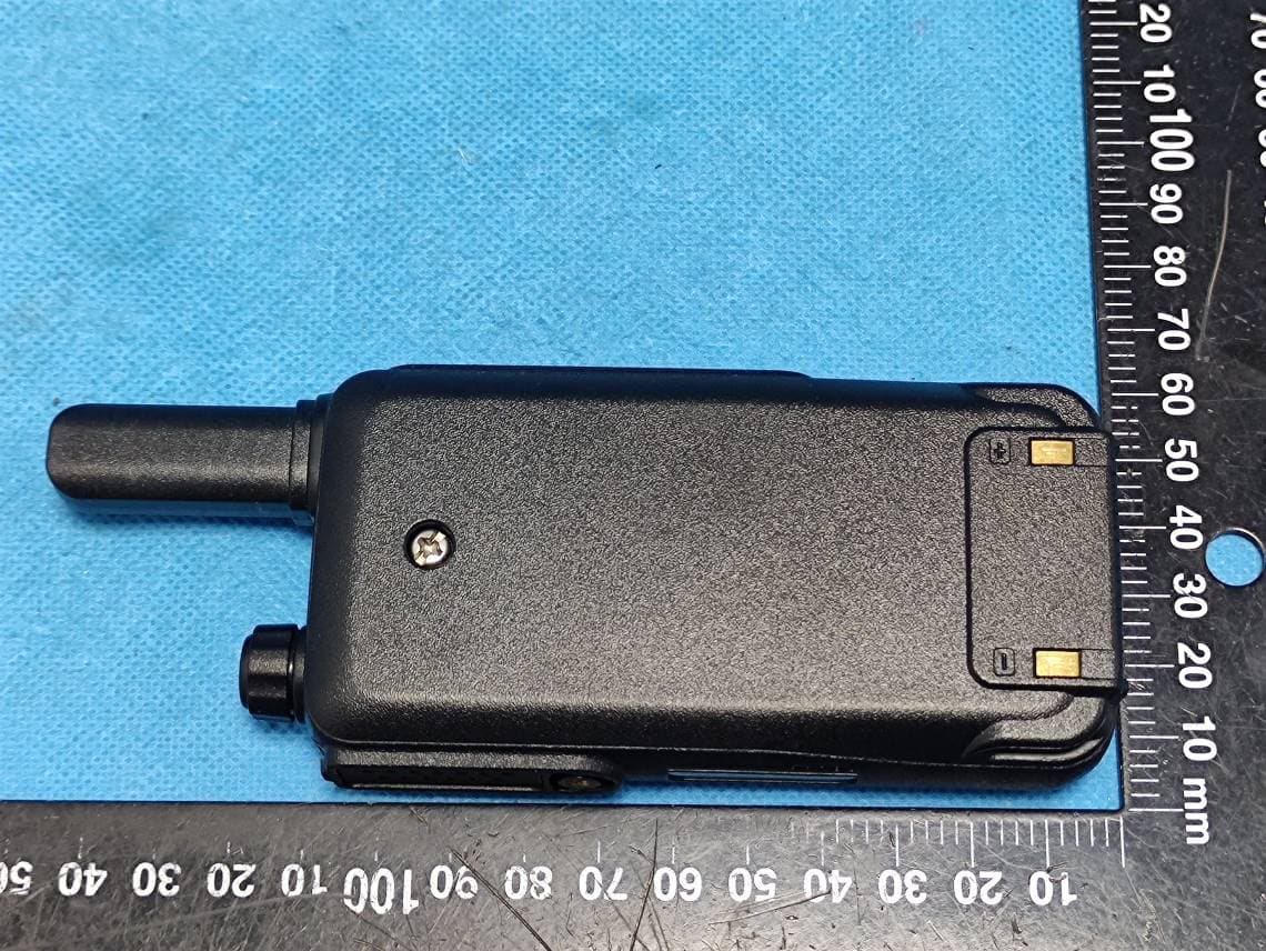
External Photos
EXHIBIT A - EUT EXTERNAL PHOTOGRAPHS UHF Antenna
Internal Photos
EXHIBIT B - EUT INTERNAL PHOTOGRAPHS
RF Exposure Info
Note: This test report is prepared for the customer shown above and for the device described herein. It may not be duplicated or used in part without prior written consent from Bay Area Compliance Laboratories Corp. (Dongguan). This report must not be used by the customer to claim product certification, approval, or endorsement by A2LA* or any agency of the Federal Government. * This report may contain data that are not covered by the A2LA accreditation and are marked with an asterisk “*”. SAR EVALUATION REPORT For QUANZHOU KAILI ELECTRONICS CO., LTD. Kaili Electronic Industrial Park(Photoelectric Information Base), Xiamei Town, Nanan, Quanzhou City, Fujian Province, China FCC ID: 2AQX5KD-C888 Report Type: Original Report Product Type: two way radio Report Number: RXM200817054-20A Report Date: 2020-10-20 Reviewed By: Rocky Xiao RF Engineer Prepared By: Bay Area Compliance Laboratories Corp. (Dongguan) No.69 Pulongcun, Puxinhu Industry Area, Tangxia, Dongguan, Guangdong, China Tel: +86-769-86858888 Fax: +86-769-86858891 www.baclcorp.com.cn Bay Area Compliance Laboratories Corp. (Dongguan) Report No.: RXM200817054-20A SAR Evaluation Report 2 of 36 Attestation of Test Results EUT Information EUT Description two way radio Tested Model KD-C888Pro FCC ID 2AQX5KD-C888 Serial Number RXM200817054-SA-S1 Test Date 2020-08-22 MODE Max. SAR Level(s) Reported(W/kg) Limit (W/kg) PTT 1g Head SAR (Face Up) 0.33 1.6 1g Body SAR (Body Back) 0.68 Applicable Standards FCC 47 CFR part 2.1093 Radiofrequency radiation exposure evaluation: portable devices RF Exposure Procedures: TCB Workshop April 2019 IEEE1528:2013 IEEE Recommended Practice for Determining the Peak Spatial-Average Specific Absorption Rate (SAR) in the Human Head from Wireless Communications Devices: Measurement Techniques IEC 62209-1:2016 Measurement procedure for the assessment of specific absorption rate of human exposure to radio frequency fields from hand-held and body-mounted wireless communication devices – Part 1: Devices used next to the ear (Frequency range of 300 MHz to 6 GHz) KDB procedures KDB 447498 D01 General RF Exposure Guidance v06 KDB 865664 D01 SAR Measurement 100 MHz to 6 GHz v01r04 KDB 865664 D02 RF Exposure Reporting v01r02 KDB 643646 D01 SAR Test for PTT Radios v01r03 Note: This wireless device has been shown to be capable of compliance for localized specific absorption rate (SAR) for General Population/Uncontrolled Exposure limits specified in FCC 47 CFR part 2.1093 and has been tested in accordance with the measurement procedures specified in IEEE 1528-2013 and RF exposure KDB procedures. The results and statements contained in this report pertain only to the device(s) evaluated. Bay Area Compliance Laboratories Corp. (Dongguan) Report No.: RXM200817054-20A SAR Evaluation Report 3 of 36 TABLE OF CONTENTS DOCUMENT REVISION HISTORY ......................................................................................................................... 4 EUT DESCRIPTION .................................................................................................................................................... 5 TECHNICAL SPECIFICATION ......................................................................................................................................... 5 REFERENCE, STANDARDS, AND GUIDELINES .................................................................................................. 6 SAR LIMITS ................................................................................................................................................................. 7 FACILITIES .................................................................................................................................................................. 8 DESCRIPTION OF TEST SYSTEM .......................................................................................................................... 9 EQUIPMENT LIST AND CALIBRATION ............................................................................................................. 14 EQUIPMENTS LIST & CALIBRATION INFORMATION .................................................................................................... 14 SAR MEASUREMENT SYSTEM VERIFICATION .............................................................................................. 15 LIQUID VERIFICATION ............................................................................................................................................... 15 SYSTEM ACCURACY VERIFICATION ........................................................................................................................... 16 SAR SYSTEM VALIDATION DATA ..................................................................................................................... 17 EUT TEST STRATEGY AND METHODOLOGY ................................................................................................. 18 TEST POSITIONS FOR DEVICE OPERATING NEXT TO A PERSON’S EAR........................................................................ 18 CHEEK/TOUCH POSITION ........................................................................................................................................... 19 EAR/TILT POSITION ................................................................................................................................................... 19 TEST POSITIONS FOR BODY-WORN AND OTHER CONFIGURATIONS .............................................................................. 20 TEST DISTANCE FOR SAR EVALUATION .................................................................................................................... 20 SAR EVALUATION PROCEDURE ................................................................................................................................. 21 OUTPUT POWER MEASUREMENT......................................................................................…
Text truncated - open the document above for the full version.
Test Report
FCC PART 95 TEST REPORT For QUANZHOU KAILI ELECTRONICS CO., LTD. Kaili Electronic Industrial Park(Photoelectric Information Base), Xiamei Town, Nanan, Quanzhou City, Fujian Province, China Report Type: Original Report Product Type: two way radio Test Engineer: Chao Gao Re port Number: RXM200817054-00B Re port Date: 2020-10-08 Reviewed B y: Oscar Ye EMC Manager Prepared By: Bay Area Compliance Laboratories Corp. (Kunshan) No.248 Chenghu Road, Kunshan, Jiangsu province, China Tel: +86-0512-86175000 Fax: +86-0512-88934268 www.baclcorp.com.cn FCC ID: 2AQX5KD-C888 Bay Area Compliance Laboratories Corp. (Kunshan) Report No.: RXM200817054-00B FCC Part 95 Page 2 of 27 TABLE OF CONTENTS GENERAL INFORMATION ....................................................................................................................................... 3 PRODUCT DESCRIPTION FOR EQUIPMENT UNDER TEST (EUT) ..................................................................................... 3 OBJECTIVE ................................................................................................................................................................... 3 RELATED SUBMITTAL(S)/GRANT(S) ............................................................................................................................. 3 TEST METHODOLOGY .................................................................................................................................................. 3 MEASUREMENT UNCERTAINTY .................................................................................................................................... 4 TEST FACILITY ............................................................................................................................................................. 4 SYSTEM TEST CONFIGURATION .......................................................................................................................... 5 DESCRIPTION OF TEST CONFIGURATION ...................................................................................................................... 5 EQUIPMENT MODIFICATIONS ....................................................................................................................................... 5 SUPPORT EQUIPMENT LIST AND DETAILS .................................................................................................................... 5 EXTERNAL I/O CABLE .................................................................................................................................................. 5 BLOCK DIAGRAM OF TEST SETUP ................................................................................................................................ 6 SUMMARY OF TEST RESULTS ............................................................................................................................... 7 TEST EQUIPMENT LIST ........................................................................................................................................... 8 FCC §2.1093 - RF EXPOSURE .................................................................................................................................... 9 MEASUREMENT RESULT .............................................................................................................................................. 9 FCC §2.1046, §95.567 - RF OUTPUT POWER ........................................................................................................ 10 APPLICABLE STANDARD ............................................................................................................................................ 10 TEST PROCEDURE ...................................................................................................................................................... 10 TEST DATA ................................................................................................................................................................ 10 FCC §2.1047, §95.575 - MODULATION CHARACTERISTIC ............................................................................. 12 APPLICABLE STANDARD ............................................................................................................................................ 12 TEST PROCEDURE ...................................................................................................................................................... 12 TEST DATA ................................................................................................................................................................ 12 FCC §2.1049, §95.573, §95.579 - AUTHOURIZED BANDWIDTH AND EMISSION MASK ............................ 19 APPLICABLE STANDARD ............................................................................................................................................ 19 TEST PROCEDURE ...................................................................................................................................................... 19 TEST DATA ................................................................................................................................................................ 19 FCC §2.1053 & §95.579 - RADIATED SPURIOUS EMISSION ............................................................................ 23 APPLICABLE STANDARD ............................................................................................................................................ 23 TEST PROCEDURE ...................................................................................................................................................... 23 TEST DATA ................................................................................................................................................................ 23 FCC§2.1055 (d), §95.565 - FREQUENCY STABILITY .......…
Text truncated - open the document above for the full version.
Contact Information
Applicant
Jacky Wang(Manager)
Test Firm
Bay Area Compliance Laboratories Corp. (Kunshan)Mr. John Chan
[email protected]+86 0512 86175000
Technical Specifications
| # | Rule Parts | Frequency Range | Power Output | Emission | Tolerance |
|---|---|---|---|---|---|
| 2 | 95B | 467.5625 MHz - 467.7125 MHz | 411.00 mW | 11K0F3E | 2.5 ppm |
Other Applications from QUANZHOU KAILI ELECTRONICS CO., LTD.
2AQX5KD-C180
Jul 12, 2023two way radio
Equipment Class
FRF - Part 95 Family Radio Face Held Transmitter
2AQX5KD-C70PRO
Mar 08, 2021Two way radio
Equipment Class
FRF - Part 95 Family Radio Face Held Transmitter
2AQX5KD-C1
Nov 29, 2020Two Way Radio
Equipment Class
FRF - Part 95 Family Radio Face Held Transmitter
2AQX5KD-C30
Nov 29, 2020Two Way Radio
Equipment Class
FRF - Part 95 Family Radio Face Held Transmitter
2AQX5KD-C70
Jul 20, 2020Two Way Radio
Equipment Class
FRF - Part 95 Family Radio Face Held Transmitter