2AR42APPC7XPL7 inch Android Panel PC PoE LED
ProDVX Europe B.V.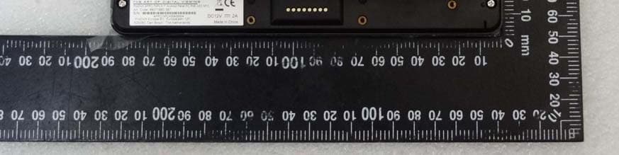
Click to zoom
Application Details
- Equipment Class
- DTS - Digital Transmission System
- Date of Grant
- Mar 22, 2021
- Application Purpose
- Original Equipment
- Date of Application
- Mar 14, 2021
- Equipment Note
- 7 inch Android Panel PC PoE LED
- Frequency Range
- 2412.00000000 - 2462.00000000
- Company
- ProDVX Europe B.V.
- Country
- Netherlands
Documents & Files
Document Text
Text extracted from the exhibit documents filed with the FCC. Open a document above to read the original.
Users Manual
7NB-RN User Manual Content Declaration ........................................................................................................................... 1 Product Instruction.............................................................................................................. 1 Insert SD Card .................................................................................................................... 2 Insert USB Devices ............................................................................................................ 2 Home Screen ...................................................................................................................... 2 System Bar .......................................................................................................................... 5 Applications ......................................................................................................................... 7 Language ............................................................................................................................. 8 Date & Time ....................................................................................................................... 10 Volume................................................................................................................................. 11 Brightness ........................................................................................................................... 11 Scheduled Sleep On/Off .................................................................................................. 12 Wi-Fi .................................................................................................................................... 16 Ethernet .............................................................................................................................. 17 Bluetooth ............................................................................................................................ 19 Virtual Keyboard ............................................................................................................... 21 Switch Input Methods ....................................................................................................... 22 Surf Online ......................................................................................................................... 22 Browse Files ...................................................................................................................... 23 Play Media ......................................................................................................................... 24 Install & Uninstall Apps .................................................................................................... 25 Install Apps ................................................................................................................... 25 Uninstall Apps............................................................................................................... 28 Reset to Factory Default .................................................................................................. 30 1 Declaration ✓ Please read the instructions carefully before equipment installation and using the device. ✓ Do not put the product in high temperature, humid or dusty environment. ✓ Do not drop, crash or break down this product. ✓ Do not power off the device when it’s formatting or upgrading, otherwise it will cause operation system error. ✓ This product is not waterproof. ✓ Use only approved add-on enhancements. Product Instruction 1. LED Indicator: Red System is booting. Green System is working properly. Light Off Power supply is off. 2. DC In Jack: powered by 12V/2A DC input 3. SD Card Slot / Cover: support external SD card 2 4. Power Key: (1).Short press sleep and wake up (2).Long press to pop out the power off and reboot dialog box 5. Headset + Microphone Jack 6. Add-on module slot: to put optional add-on module 7. Micro-USB Port: support USB 2.0 high speed 480Mbps 8. USB Port: support USB 2.0 high speed 480Mbps 9. Ethernet RJ45 Port: support Ethernet connection (10/100Mbps LAN) 10. Speaker: audio output 11. VESA Mount Holes: for installing the bracket 12. WIFI: 802.11b/g/n/ac 2.4G/5G 13. Temperature:Operation: 0°C ~ 40°C ( 32F ~104F) Storage: -10°C ~ 55°C (14°F ~ 131°F) Insert SD Card This product supports external SD card. Please insert your SD card into the SD Card Slot (#3 in Product Instruction) on the top of this product. Insert USB Devices This product supports USB and Micro-USB to deal with your files. USB Plug your USB memory into the USB port (#8 in Product Instruction) on the bottom of this product, and then you can do the file operations via the File Browser. (See the details in Browse Files). Micro-USB Connect the Micro-USB port (#7 in Product Instruction) on the bottom of this product and the USB port on your computer with a Micro-USB-to-USB cable. In the "USB Debug Connection" window that automatically pops up, click the "USB Preferences" button and select "File Transfer" to make the device visible on your computer. Home Screen In the home screen, you can long-press the blank space to change the 3 wallpaper or drag widgets to desktop. Change Wallpaper: 1. Click “Wallpapers”. 2. Select an image from the Myphotos preset. 4 3. Click “Set wallpaper” on the upper-left corner of the screen to apply the wallpaper. Add Widgets: 1. Click “Widgets”. 2. Long-press a widget and drag it to desktop. 5 3. If you want to remove an icon, long press the widget and drag it to the top left corner of the screen, "× ". System Bar Navigation Buttons 1.Power: Power off and restart. 6 2. Volume-: Decrease the system volume. 3. Back: Return to the previous page. 4. Home: Return to the home screen. 5. Recents: Switch between recently used apps. To remove an application from the list, swipe left or right to remov…
Text truncated - open the document above for the full version.
External Photos
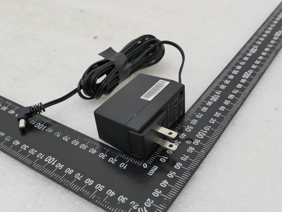
International Standards Laboratory Corp. Report Number: ISL-20LR400P Appendix Photographs of EUT of Product Name 7 inch Android Panel PC PoE LED Model APPC-7XPL; APPC-7XPLN Brand ProDVX International Standards Laboratory Corp. Report Number: ISL-20LR400P -1- EUT-1. all EUT-2. International Standards Laboratory Corp. Report Number: ISL-20LR400P -2- EUT-3. EUT-4. International Standards Laboratory Corp. Report Number: ISL-20LR400P -3- EUT-5. EUT-6. International Standards Laboratory Corp. Report Number: ISL-20LR400P -4- EUT-7.
ID Label/Location Info
FCC ID LABEL FORMAT AND LOCATION Applicant: ProDVX Europe B.V. FCC ID: 2AR42APPC7XPL
Internal Photos
International Standards Laboratory Corp. Report Number: ISL-20LR400P Appendix Photographs of EUT of Product Name 7 inch Android Panel PC PoE LED Model APPC-7XPL; APPC-7XPLN Brand ProDVX International Standards Laboratory Corp. Report Number: ISL-20LR400P -1- EUT-1. EUT-2. International Standards Laboratory Corp. Report Number: ISL-20LR400P -2- EUT-3. EUT-4. International Standards Laboratory Corp. Report Number: ISL-20LR400P -3- EUT-5. EUT-6. International Standards Laboratory Corp. Report Number: ISL-20LR400P -4- EUT-7. EUT-8. antenna International Standards Laboratory Corp. Report Number: ISL-20LR400P -5- EUT-9. EUT-10. International Standards Laboratory Corp. Report Number: ISL-20LR400P -6- EUT-11. EUT-12. International Standards Laboratory Corp. Report Number: ISL-20LR400P -7- EUT-13. EUT-14. International Standards Laboratory Corp. Report Number: ISL-20LR400P -8- EUT-15. EUT-16. International Standards Laboratory Corp. Report Number: ISL-20LR400P -9- EUT-17. EUT-18. International Standards Laboratory Corp. Report Number: ISL-20LR400P -10- EUT-19. EUT-20. International Standards Laboratory Corp. Report Number: ISL-20LR400P -11- EUT-21. EUT-22. International Standards Laboratory Corp. Report Number: ISL-20LR400P -12- EUT-23. EUT-24. Ant International Standards Laboratory Corp. Report Number: ISL-20LR400P -13- EUT-25.
RF Exposure Info
FCC ID: 2AR42APPC7XPL International Standards Laboratory Corp. 1. Maximum Permissible Exposure (MPE) Standard Applicable According to §1.1307(b)(1), systems operating under the provisions of this section shall be operated in a manner that ensure that the public is not exposed to radio frequency energy level in excess of the Commission’s guideline. This is a Mobile device, the MPE is required. According to §1.1310 and §2.1091 RF exposure is calculated. Limits for Maximum Permissive Exposure (MPE) Frequency Range (MHz) Electric Field Strength (V/m) Magnetic Field Strength (A/m) Power Density (mW/cm 2 ) Averaging Time (minute) Limits for General Population/Uncontrolled Exposure 0.3-1.34 614 1.63 *(100) 30 1.34-30 824/f 2.19/f *(180/f 2 ) 30 30-300 27.5 0.073 0.2 30 300-1500 / / F/1500 30 1500-15000 / / 1.0 30 F = frequency in MHz * = Plane-wave equipment power density FCC ID: 2AR42APPC7XPL International Standards Laboratory Corp. Maximum Permissible Exposure (MPE) Evaluation 2.4GHz mode: The worst case: refer to FCC test report for detail measurement date. Power measurement: BDR mode Frequency (MHz) Output Power (dBm) Output Power (W) Limit (W) Low 8.33 0.00680 1 Mid 7.68 0.00585 1 High 7.46 0.00557 1 Prediction of MPE limit at a given distance Equation from page 18 of OET Bulletin 65, Edition 97-01 S=PG/4πR 2 Where: S = Power density P = Power input to antenna G = Power gain of the antenna in the direction of interest relative to an isotropic radiator R = Distance to the center of radiation of the antenna Maximum output power at antenna input terminal: 8.33 (dBm) Maximum output power at antenna input terminal: 6.807693587 (mW) Tune-Up power Tolerance: 1 dB Duty cycle: 100 (%) Maximum Pav : 8.570378452 (mW) Antenna gain (typical): 2.2 (dBi) Maximum antenna gain: 1.659586907 (numeric) Prediction distance: 20 (cm) MPE limit for uncontrolled exposure at prediction 1 (mW/cm^2) Power density at predication frequency at 20 (cm) 0.0028311 (mW/cm^2) Measurement Result: The predicted power density level at 20 cm is 0.0028311 mW/cm 2 . This is below the uncontrolled exposure limit of 1 mW/cm 2 . FCC ID: 2AR42APPC7XPL International Standards Laboratory Corp. Mode Freq. (MHz) Output Power (dBm) Duty Factor (dB) Total Output Power (dBm) Output Power Limit (dBm) BLE 4.0 2402 4.150 0.00 4.15 30.00 2442 3.687 0.00 3.69 30.00 2480 2.897 0.00 2.90 30.00 Prediction of MPE limit at a given distance Equation from page 18 of OET Bulletin 65, Edition 97-01 S=PG/4πR 2 Where: S = Power density P = Power input to antenna G = Power gain of the antenna in the direction of interest relative to an isotropic radiator R = Distance to the center of radiation of the antenna Maximum output power at antenna input terminal: 4.15 (dBm) Maximum output power at antenna input terminal: 2.600159563 (mW) Tune-Up power Tolerance: 1 dB Duty cycle: 100 (%) Maximum Pav : 3.273406949 (mW) Antenna gain (typical): 2.2 (dBi) Maximum antenna gain: 1.659586907 (numeric) Prediction distance: 20 (cm) MPE limit for uncontrolled exposure at prediction 1 (mW/cm^2) Power density at predication frequency at 20 (cm) 0.0010813 (mW/cm^2) Measurement Result: The predicted power density level at 20 cm is 0.0010813 mW/cm 2 . This is below the uncontrolled exposure limit of 1 mW/cm 2 . FCC ID: 2AR42APPC7XPL International Standards Laboratory Corp. Mode Freq. (MHz) Output Power (dBm) Duty Factor (dB) Total Output Power (dBm) Output Power Limit (dBm) Chain 0 Chain 1 Chain 2 Chain 3 802.11g 2412 24.06 0.00 24.06 30.00 2437 24.10 0.00 24.10 30.00 2462 24.19 0.00 24.19 30.00 Prediction of MPE limit at a given distance Equation from page 18 of OET Bulletin 65, Edition 97-01 S=PG/4πR 2 Where: S = Power density P = Power input to antenna G = Power gain of the antenna in the direction of interest relative to an isotropic radiator R = Distance to the center of radiation of the antenna Maximum output power at antenna input terminal: 24.19 (dBm) Maximum output power at antenna input terminal: 262.4218543 (mW) Tune-Up power Tolerance: 1 dB Duty cycle: 100 (%) Maximum Pav : 330.369541 (mW) Antenna gain (typical): 2.2 (dBi) Maximum antenna gain: 1.659586907 (numeric) Prediction distance: 20 (cm) MPE limit for uncontrolled exposure at prediction 1 (mW/cm^2) Power density at predication frequency at 20 (cm) 0.1091316 (mW/cm^2) Measurement Result: The predicted power density level at 20 cm is 0.1091316 mW/cm 2 . This is below the uncontrolled exposure limit of 1 mW/cm 2 . FCC ID: 2AR42APPC7XPL International Standards Laboratory Corp. 5180MHz – 5240MHz Mode: The worst case of Average power a mode: refer to FCC test report for detail measurement date. Power measurement: Band Mode Freq. (MHz) Output Power (dBm) Duty Factor (dB) Total Output Power (dBm) Output Power Limit (dBm) Chain 0 Chain 1 Chain 2 Chain 3 UNII-1 11a 5180 16.36 0.16 16.52 23.98 5200 16.12 0.16 16.28 23.98 5240 16.29 0.16 16.45 23.98 Prediction of MPE limit at a given distance Equation from page 18 of OET Bulletin 65, Edition 97-01 S=PG/4πR 2 Where: S = Power density P = Power input to antenna G = Power gain of the antenna in the direction of interest relative to an isotropic radiator R = Distance to the center of radiation of the antenna Maximum output power at antenna input terminal: 16.52 (dBm) Maximum output power at antenna input terminal: 44.87453899 (mW) Tune-Up power Tolerance: 1 dB Duty cycle: 100 (%) Maximum Pav : 56.49369748 (mW) Antenna gain (typical): 4.93 (dBi) Maximum antenna gain: 3.111716337 (numeric) Prediction distance: 20 (cm) MPE limit for uncontrolled exposure at prediction 1 (mW/cm^2) Power density at predication frequency at 20 (cm) 0.0349905 (mW/cm^2) Measurement Result The predicted power density level at 20 cm is 0.0349905 mW/cm 2 . This is below the uncontrolled exposure limit of 1 mW/cm 2 . FCC ID: 2AR42APPC7XPL International Standards Laboratory Corp. 5260MHz – 5320MHz Mode: The worst case of Average power a mode: refer to FCC test report for detail measurement date. Power measur…
Text truncated - open the document above for the full version.
Test Report
Page: 1 of 97 TEST REPORT of FCC Part 15 Subpart C New Application; Class I PC; Class II PC Product : 7 inch Android Panel PC PoE LED Brand: ProDVX Model: APPC-7XPL, APPC-7XPLN Model Difference: For different markets FCC ID: 2AR42APPC7XPL FCC Rule Part: §15.247, Cat: DTS Applicant: ProDVX Europe B.V. Address: Europalaan 12F, 5232 BC Den Bosch, The Netherlands Test Performed by: International Standards Laboratory Corp. <LT Lab.> *Site Registration No. BSMI: SL2-IN-E-0013; MRA TW0997; TAF: 0997; IC: IC4067B-4; *Address: No. 120, Lane 180, San Ho Tsuen, Hsin Ho Rd. Lung-Tan Hsiang, Tao Yuan County 325, Taiwan TEL: +886-3-263-8888 FAX: +886-3-263-8899 Report No.: ISL-20LR400FCDTS Issue Date : 2021/01/15 Test results given in this report apply only to the specific sample(s) tested and are traceable to na- tional or international standard through calibration of the equipment and evaluating measurement un- certainty herein. The uncertainty of the measurement does not in- clude in consideration of the test result unless the customer required the determination of uncertainty via the agreement, regulation or standard document specification. This test report shall not be reproduced except in full, without the written approval of International Standards Laboratory Corp. -2 of 97- FCC ID: 2AR42APPC7XPL International Standards Laboratory Corp. Report Number: ISL-20LR400FCDTS VERIFICATION OF COMPLIANCE Applicant: ProDVX Europe B.V. Product Description: 7 inch Android Panel PC PoE LED Brand Name: ProDVX Model No.: APPC-7XPL, APPC-7XPLN Model Difference: For different markets FCC ID: 2AR42APPC7XPL Date of test: 2020/12/04 ~ 2021/01/14 Date of EUT Received: 2020/12/04 We hereby certify that: All the tests in this report have been performed and recorded in accordance with the standards de- scribed above and performed by an independent electromagnetic compatibility consultant, Interna- tional Standards Laboratory Corp. The test results contained in this report accurately represent the measurements of the characteristics and the energy generated by sample equipment under test at the time of the test. The sample equip- ment tested as described in this report is in compliance with the limits of above standards. Test By: Date: 2021/01/15 Barry Lee / Senior Engineer Prepared By: Date: 2021/01/15 Gigi Yeh / Senior Engineer Approved By: Date: 2021/01/15 Jerry Liu / Technical Manager -3 of 97- FCC ID: 2AR42APPC7XPL International Standards Laboratory Corp. Report Number: ISL-20LR400FCDTS Version Version No. Date Description 00 2021/01/15 Initial creation of document Uncertainty of Measurement Description Of Test Uncertainty Conducted Emission (AC power line) 2.586 dB Field Strength of Spurious Radia- tion <=30MHz: 2.96dB 30-1GHz: 4.22 dB 1-40 GHz: 4.08 dB Conducted Power 2.412 GHz: 1.30 dB 5.805 GHz: 1.55 dB Power Density 2.412 GHz:1.30 dB 5.805 GHz: 1.67 dB Frequency 0.0032% -4 of 97- FCC ID: 2AR42APPC7XPL International Standards Laboratory Corp. Report Number: ISL-20LR400FCDTS Table of Contents 1 General Information ................................................................................................................... 6 1.1 Related Submittal(s) / Grant (s) ..................................................................................................... 8 1.2 Test Methodology .......................................................................................................................... 8 1.3 Test Facility .................................................................................................................................... 8 1.4 Special Accessories ........................................................................................................................ 8 1.5 Equipment Modifications ............................................................................................................... 8 2 System Test Configuration ......................................................................................................... 9 2.1 EUT Configuration ........................................................................................................................ 9 2.2 EUT Exercise ................................................................................................................................. 9 2.3 Test Procedure ................................................................................................................................ 9 2.4 Configuration of Tested System ................................................................................................... 10 3 Summary of Test Results .......................................................................................................... 11 4 Description of Test Modes ........................................................................................................ 11 5 Conduced Emission Test .......................................................................................................... 12 5.1 Standard Applicable: .................................................................................................................... 12 5.2 Measurement Equipment Used: ................................................................................................... 12 5.3 EUT Setup: ................................................................................................................................... 12 5.4 Measurement Procedure: ............................................................................................................. 13 5.5 Measurement Result: ................................................................................................................... 13 6 Peak Output Power ................................................................................................................. 16 6.1 Standard Applicable: ............................................................................................................…
Text truncated - open the document above for the full version.
Test Setup Photos
FCC ID: 2AR42APPC7XPL International Standards Laboratory Corp. Report Number: ISL-20LR400FCDTS APPENDIX 1 PHOTOGRAPHS OF SET UP FCC ID: 2AR42APPC7XPL International Standards Laboratory Corp. Report Number: ISL-20LR400FCDTS Radiated Emission Set up Photos FCC ID: 2AR42APPC7XPL International Standards Laboratory Corp. Report Number: ISL-20LR400FCDTS FCC ID: 2AR42APPC7XPL International Standards Laboratory Corp. Report Number: ISL-20LR400FCDTS Conducted Emission Set up Photo
Contact Information
Applicant
Patrick van Schaik(Director)
Technical Contact
International Standards Laboratory Corp.Jerry Liu
[email protected]886-3-263-8888
No. 120, Lane 180, Hsin Ho Rd., Lung-Tan Dist., · Taiwan
Non-Technical Contact
International Standards Laboratory Corp.Jerry Liu
[email protected]886-3-263-8888
Test Firm
International Standards Laboratory Corp.Benson Chen
Technical Specifications
| # | Rule Parts | Frequency Range | Power Output |
|---|---|---|---|
| 2 | 15C | 2.41 GHz - 2.46 GHz | 260.00 mW |
Other Applications from ProDVX Europe B.V.
2AR42APPC10SLBE
May 08, 2023ProDVX APPC-10SLBe
Equipment Class
NII - Unlicensed National Information Infrastructure TX
2AR42APPC10SLB
Jun 15, 202010 inch Android Panel PC (SoC)
Equipment Class
JBC - Part 15 Class B Computing Device/Personal Computer