2AR8X-CK721DCK721
Cooler Master Technology Inc.
Click to zoom
Application Details
- Equipment Class
- DXX - Part 15 Low Power Communication Device Transmitter
- Date of Grant
- Apr 28, 2021
- Application Purpose
- Original Equipment
- Date of Application
- Apr 28, 2021
- Equipment Note
- CK721
- Frequency Range
- 2403.00000000 - 2475.00000000
- Country
- Taiwan
Documents & Files
Document Text
Text extracted from the exhibit documents filed with the FCC. Open a document above to read the original.
Users Manual
CK721 WIRELESS SETUP GUIDE A. USING 2.4 GHZ - AN OVERVIEW If the physical switch is toggled to Bluetooth or 2.4 GHz Mode Please charge your new keyboard for at least 2 hours before using for the first time. IMPORTANT 1. Toggle the physical switch on the side of the keyboard to enter Bluetooth Mode. 2. Press and hold FN + DEL/PGUP/PGDN for 5 seconds to enter pairing mode. The indicator will rapidly flash BLUE 3 times one every second to confirm you are in Pairing Mode. 3. If pairing is successful, the indicator will light up with a solid WHITE light for 3 seconds. If unsuccessful, the keyboard will enter Sleep Mode after 30 seconds. In Sleep Mode, all the keyboard lighting will be turned off. 1. When the Bluetooth mode is activated, the keyboard will connect to the previous synced wireless device (DEL/PGUP/PGDN) automatically within seconds. 2. If successfully connected, the indicator will light up with a solid WHITE light for 3 seconds. If unsuccessful, the keyboard will enter Sleep Mode after 30 seconds. In Sleep Mode, all the keyboard lighting will be turned off. 3. To connect to a specific paired device, press FN + DEL/PGUP/PGDN after activating Bluetooth mode to connect to the corresponding device. The keyboard will connect to the device if successful and enter sleep mode after 30 seconds if device is not found or fails to connect. 1. Toggle the physical switch on the side of the keyboard to enter Bluetooth Mode. 1. Press FN + DEL/PGUP/PGDN to switch to the corresponding paired device. 2. Press and hold FN + DEL/PGUP/PGDN for 5 seconds to enter pairing mode. The indicator will rapidly flash BLUE 3 times one every second to confirm you are in Pairing Mode. 3. If pairing is successful, the indicator will light up with a solid WHITE light for 3 seconds. If unsuccessful, the keyboard will enter Sleep Mode after 30 seconds. In Sleep Mode, all the keyboard lighting will be turned off. 2.4 GHz MODE INDICATOR LIGHT RULE CHARGING WIRED MODE BLUETOOTH MODE 4. To pair with other devices, simply unplug the dongle and re-plug into another device. If pairing is successful, the indicator will light up with a solid WHITE light for 3 seconds. If unsuccessful, the keyboard will enter Sleep Mode after 30 seconds. In Sleep Mode, all the keyboard lighting will be turned off. 3. If successfully connected, the indicator will light up with a solid WHITE light for 3 seconds. If unsuccessful, the keyboard will enter Sleep Mode after 30 seconds. In Sleep Mode, all the keyboard lighting will be turned off. 2. Plug the included dongle into the desired device. The keyboard should automatically connect to the device. 1. Toggle the physical switch on the side of the keyboard to enter 2.4 GHz Mode. The indicator will continuously flash a BLUE light one every second to confirm it is trying to connect to a device. 1. Toggle the physical switch on the side of the keyboard to enter 2.4 GHz Mode. Press and hold FN + Enter for 5 seconds to enter pairing mode. The indicator will rapidly flash BLUE 3 times one every second to confirm you are in Pairing Mode. 2. Plug the included dongle into the desired device. The keyboard should automatically connect to the device. 3. If pairing is successful, the indicator will light up with a solid WHITE light for 3 seconds. If unsuccessful, the keyboard will enter Sleep Mode after 30 seconds. In Sleep Mode, all the keyboard lighting will be turned off. B. MANUALLY PAIRING 2.4 GHZ DONGLE TO THE KEYBOARD The keyboard will switch to Wired Mode automatically as it is connected to a PC or laptop. If the physical switch is toggled to Wired Mode The keyboard will switch to Wired Mode automatically as the physical switch is toggled to Wired and it is connected to a PC or laptop. Turning On Bluetooth for the First Time Turning On Bluetooth After the First Time The keyboard will begin charging when it is plugged into a PC, laptop, or power source. The indicator light will be RED when charging and change to GREEN when battery level is full. The CAPSLK indicator will light up with a solid WHITE light when turn on CAPSLK key, and turn off when turn off CAPLSK key. *In Wired Mode, the indicator will change to GREEN for 3 seconds then turn off when the battery level is full. When the keyboard is plugged into a PC, laptop, or power source, the indicator will show a RED light when charing and change to GREEN when battery level is full. Press FN will show the pairing status of each location (DEL, PGUP or PGDN) with WHITE light. 1. In Pairing Mode, the indicator will rapidly flash BLUE 3 times one every second. 2. In Connecting Mode, the indicator will continuously flash a BLUE light one every second. 3. If Pairing / Connecting is successful, the indicator will light up with a solid WHITE light for 3 seconds. 1. When the battery level falls below 15%, the indicator will rapidly flash RED light 3 times every 20 seconds. This indicator lighting will repeat until the keyboard enter Sleep Mode or is connected to the PC, laptop or power source. *The Low Power Mode percentage can be customized via Cooler Master software. 2. When the battery level falls below 5%, the keyboard will go into Deep Sleep Mode. All lighting will be turned off - including the indicator. If the physical switch is toggled to Wired Mode The keyboard will remain connected to the wireless device and begin charging when it is plugged into a PC, laptop, or power source. The indicator light will be RED when charging and change to GREEN when battery level is full. If the physical switch is toggled to Bluetooth or 2.4 GHz Mode SWITCHING TO WIRED MODE CHARGING THE KEYBOARD A. CAPSLK Indicator B. Wireless Mode C. Charging Status Indicator D. Low Battery Scenario E. Indicator on DEL/PGUP/PGDN A. USING BLUETOOTH - AN OVERVIEW B. MANUALLY PAIRING DEVICES TO THE KEYBOARD C. SWITCH PAIRED DEVICES Wenn der physikalische Schalter auf Bluetooth oder 2,4-GHz-Modus eingestellt ist WICHTIG 1. Stellen Sie zum Aufrufen des Bluetooth-Modus den Schalter an der S…
Text truncated - open the document above for the full version.
Cover Letter(s)
Cooler Master Technology Inc. Agent Authorization Company: Cooler Master Technology Inc. Address: 8F., No. 788-1, Zhongzheng Rd., Zhonghe Dist., New Taipei City, 23586 Taiwan Product Name: CK721 Model Number(s): CK-721-D, 721-D Product Description: CK721 We authorize MiCOM Labs Inc., 575 Boulder Court, Pleasanton, California 94566, USA, to act on our behalf on all matters concerning the certification of above named equipment. We declare that MiCOM Labs Inc. is allowed to forward all information related to the approval and certification of equipment to the regulatory agencies as required and to discuss any issues concerning the approval application. Any and all acts carried out by MiCOM Labs on our behalf shall have the same effect as acts of our own. Signature: Date: Apr. 20, 2021 Name: Jane Cai Title: Cooler Master Peripheral BU LB Company: Cooler Master Technology Inc.
Cover Letter(s)
Cooler Master Technology Inc. Office of Engineering Technology Federal Communications Commission 7435 Oakland Mills Road Columbia, MD 21046 USA Date: Apr. 20, 2021 Subject; Request for Confidentiality FCC ID: 2AR8X-CK721D To Whom It May Concern, Pursuant to the provisions of the Commission’s rules Title 47 Sections §0.457 and §0.459, we are requesting the Commission to withhold the following attachment(s) as confidential documents from public disclosure indefinitely. T hese documents contain detailed system and equipment descriptions and are considered as proprietary information in operation of the equipment. The public disclosure of these documents might be harmful to our company and would give competitors an unfair advantage in the market. Schematic Diagram Block Diagram Parts List Operational Description It is our understanding that all measurement test reports, FCC ID label format and correspondence during the certification review process cannot be granted as confidential documents and this information will be available for public review once the grant of equipment authorization is issued. Sincerely, Signature: Name: Jane Cai Title: Cooler Master Peripheral BU LB
Cover Letter(s)
Model Difference Declaration To Whom It May Concern, We, Cooler Master Technology Inc.(CK721) Trademark:Cooler Master; Model Number:CK-721-D, 721-D; All model’s the function, software and electric circuit are the same, only with a product color, appearance and model named different for commercial purpose. Test sample model: CK-721-D. Please contact me if you have any question. Name: Jane Cai Date: Apr. 20, 2021 Title: Cooler Master Peripheral BU LB Signature of applicant:
External Photos
Annex A External Photos Test Model No.: CK-721-D Page 1 of 3 Test Model No.: CK-721-D Page 2 of 3 Test Model No.: CK-721-D Page 3 of 3
ID Label/Location Info
FCC ID LABEL: Ca. 3mm x 7mm Label Location FCC ID: 2AR8X-CK721D
Internal Photos
Annex B Internal Photo Test Model No.: CK-721-D Page 1 of 2 Antenna Test Model No.: CK-721-D Page 2 of 2
Test Report
Page 1 of 28 Report No.: HK2103090617-E FCC TEST REPORT Test report On Behalf of Cooler Master Technology Inc. For CK721 Model No.: CK-721-D, 721-D FCC ID: 2AR8X-CK721D Prepared for : Cooler Master Technology Inc. 8F., No. 788-1, Zhongzheng Rd., Zhonghe Dist., New Taipei City, 23586 Taiwan Prepared By : Shenzhen HUAK Testing Technology Co., Ltd. 1F, B2 Building, Junfeng Zhongcheng Zhizao Innovation Park, Fuhai Street, Bao'an District, Shenzhen, China Date of Test: Mar. 09, 2021 ~Apr. 26, 2021 Date of Report: Apr. 26, 2021 Report Number: HK2103090617-E Page 2 of 28 Report No.: HK2103090617-E TEST RESULT CERTIFICATION Applicant’s name ................. : Cooler Master Technology Inc. Address ................................. : 8F., No. 788-1, Zhongzheng Rd., Zhonghe Dist., New Taipei City, 23586 Taiwan Manufacture's Name ............ : CHUAND ELECTRONIC & TECHNOLOGY CO., LTD. Address ................................. : Sijia Industrial Zone, Shijie Town, Dongguan City, P. R. China Product description Trade Mark: Cooler Master Product name ........................... : CK721 Model and/or type reference : CK-721-D, 721-D Standards ............................. : FCC Rules and Regulations Part 15 Subpart C Section 15.249 ANSI C63.10: 2013 This publication may be reproduced in whole or in part for non-commercial purposes as long as the Shenzhen HUAK Testing Technology Co., Ltd. is acknowledged as copyright owner and source of the material. Shenzhen HUAK Testing Technology Co., Ltd. takes no responsibility for and will not assume liability for damages resulting from the reader's interpretation of the reproduced material due to its placement and context. Date of Test ............................................ : Date (s) of performance of tests ............. : Mar. 09, 2021 ~Apr. 26, 2021 Date of Issue ........................................... : Apr. 26, 2021 Test Result .............................................. : Pass Testing Engineer : (Gary Qian) Technical Manager : (Eden Hu) Authorized Signatory : (Jason Zhou) Page 3 of 28 Report No.: HK2103090617-E Table of Contents Page 1 . TEST SUMMARY 5 1.1 . Test Procedures And Results 5 1.2 . Test Facility 5 1.3 . Measurement Uncertainty 5 2 . GENERAL INFORMATION 6 2.1 . General Description Of EUT 6 2.2 . Operation of EUT during testing 7 2.3 . Description Of Test Setup 8 2.4 . Measurement Instruments List 9 3 . CONDUCTED EMISSIONS TEST 10 3.1. Conducted Power Line Emission Limit 10 3.2. Test Setup 10 3.3. Test Procedure 10 3.4. Test Result 11 4. RADIATED EMISSION TEST 13 4.1. Radiation Limit 13 4.2. Test Setup 13 4.3. Test Procedure 14 4.4. Test Result 14 5. BAND EDGE 20 5.1. Limits 20 5.2. Test Procedure 20 5.3. Test Result 21 6. OCCUPIED BANDWIDTH MEASUREMENT 23 6.1. Test Setup 23 6.2. Test Procedure 23 6.3. Measurement Equipment Used 23 6.4. Test Result 23 7. ANTENNA REQUIREMENT 25 8. PHOTOGRAPH OF TEST 26 9. PHOTOS OF THE EUT 28 Page 4 of 28 Report No.: HK2103090617-E ** Modifited History ** Revison Description Issued Data Remark Revsion 1.0 Initial Test Report Release Apr. 26, 2021 Jason Zhou Page 5 of 28 Report No.: HK2103090617-E 1. TEST SUMMARY 1.1. Test Procedures And Results DESCRIPTION OF TEST SECTION NUMBERRESULT CONDUCTED EMISSIONS TEST 15.207 COMPLIANT RADIATED EMISSION TEST 15.249(a) /15.209 COMPLIANT BAND EDGE 15.249(d)/15.205 COMPLIANT OCCUPIED BANDWIDTH MEASUREMENT 15.215(c) COMPLIANT ANTENNA REQUIREMENT 15.203 COMPLIANT 1.2. Test Facility Te s t F i r m : Shenzhen HUAK Testing Technology Co., Ltd. Address : 1F, B2 Building, Junfeng Zhongcheng Zhizao Innovation Park, Fuhai Street, Bao'an District, Shenzhen, China 1.3. Measurement Uncertainty Measurement Uncertainty Conducted Emission Expanded Uncertainty =2.71dB, k=2 Radiated emission expanded uncertainty(9kHz-30MHz) = 4.26dB, k=2 Radiated emission expanded uncertainty(30MHz-1000MHz)= 3.90dB, k=2 Radiated emission expanded uncertainty(Above 1GHz) = 4.28dB, k=2 Page 6 of 28 Report No.: HK2103090617-E 2. GENERAL INFORMATION 2.1. General Description Of EUT Equipment CK721 Model Name CK-721-D Serial Model 721-D Model Difference All model’s the function, software and electric circuit are the same, only with a product color, appearance and model named different. Test sample model: CK-721-D. FCC ID 2AR8X-CK721D Antenna Type PCB Antenna Antenna Gain 0dBi Operation frequency 2403-2475MHz Number of Channels 38CH Modulation Type GFSK Power Source DC 5V from USB Power Rating DC 5V from USB Page 7 of 28 Report No.: HK2103090617-E 2.1.1. Carrier Frequency of Channels Channel Frequency (MHz) Channel Frequency (MHz) Channel Frequency (MHz) 1 2403 14 2427 27 2453 2 2404 15 2429 28 2455 3 2405 16 2431 29 2457 4 2407 17 2433 30 2459 5 2409 18 2435 31 2461 6 2411 19 2437 32 2463 7 2413 20 2439 33 2465 8 2415 21 2441 34 2467 9 2417 22 2443 35 2469 10 2419 23 2445 36 2471 11 2421 24 2447 37 2473 12 2423 25 2449 38 2475 13 2425 26 2451 2.2. Operation of EUT during testing Operating Mode The mode is used: Transmitting mode Low Channel: 2403MHz Middle Channel: 2441MHz High Channel: 2475MHz Page 8 of 28 Report No.: HK2103090617-E 2.3. Description Of Test Setup Operation of EUT during conducted testing and radiation below 1GHz testing: AC Plug Operation of EUT during radiation above 1GHz testing: PC information Model: ThinkPad X220i Input: 20V, 3.25A/4.5A The sample was placed (0.8m below 1GHz, 1.5m above 1GHz) above the ground plane of 3m chamber. Measurements in both horizontal and vertical polarities were performed. During the test, each emission was maximized by: having the EUT continuously working, investigated all operating modes, rotated about all 3 axis (X, Y & Z) and considered typical configuration to obtain worst position, manipulating interconnecting cables, rotating the turntable, varying antenna height from 1m to 4m in both horizontal and vertical polarizations. The emissions worst-case are shown in Test Results of the following pages. The worst case is X position. PC EUT PC EUT Page 9 of…
Text truncated - open the document above for the full version.
Test Setup Photos
Test model:CK-721-D Radiated Emission Conducted Power Line Emission test
Contact Information
Applicant
Monica Chiu(IO-CGP PM)
Technical Contact
Test Firm
Shenzhen HUAK Testing Technology Co., Ltd.Jason Zhou
[email protected]+86-755-23029901
Technical Specifications
| # | Rule Parts | Frequency Range | Power Output |
|---|---|---|---|
| 1 | 15C | 2.40 GHz - 2.48 GHz | - |
Other Applications from Cooler Master Technology Inc.
2AR8X-CH351
Aug 20, 2024Gaming Headset
Equipment Class
DSS - Part 15 Spread Spectrum Transmitter2AR8X-CMHS-D
Aug 20, 2024Dongle
Equipment Class
DTS - Digital Transmission System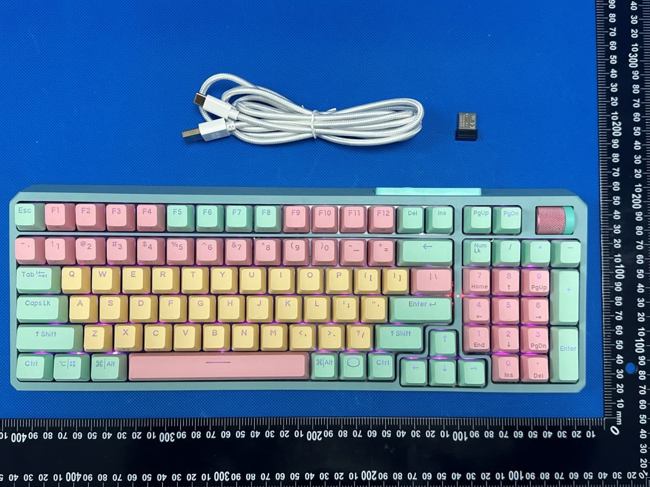
2AR8X-MK770MCKR1US
Jul 15, 2023MK770
Equipment Class
DSS - Part 15 Spread Spectrum Transmitter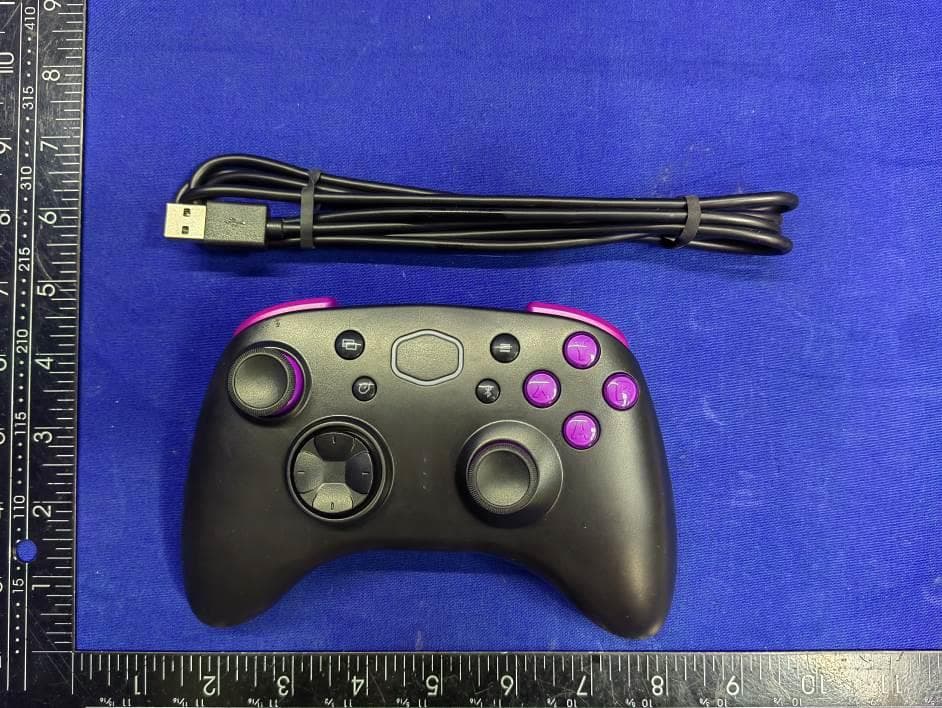
2AR8X-CMSCBT
Feb 26, 2023Storm Gaming Controller
Equipment Class
DSS - Part 15 Spread Spectrum Transmitter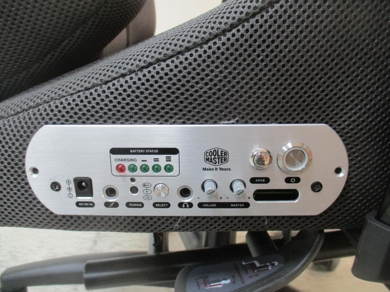
2AR8X-IXC-SX1
Jan 04, 2023Synk X
Equipment Class
DSS - Part 15 Spread Spectrum Transmitter