2AR8X-MH670AWDMH670 Dongle
Cooler Master Technology Inc.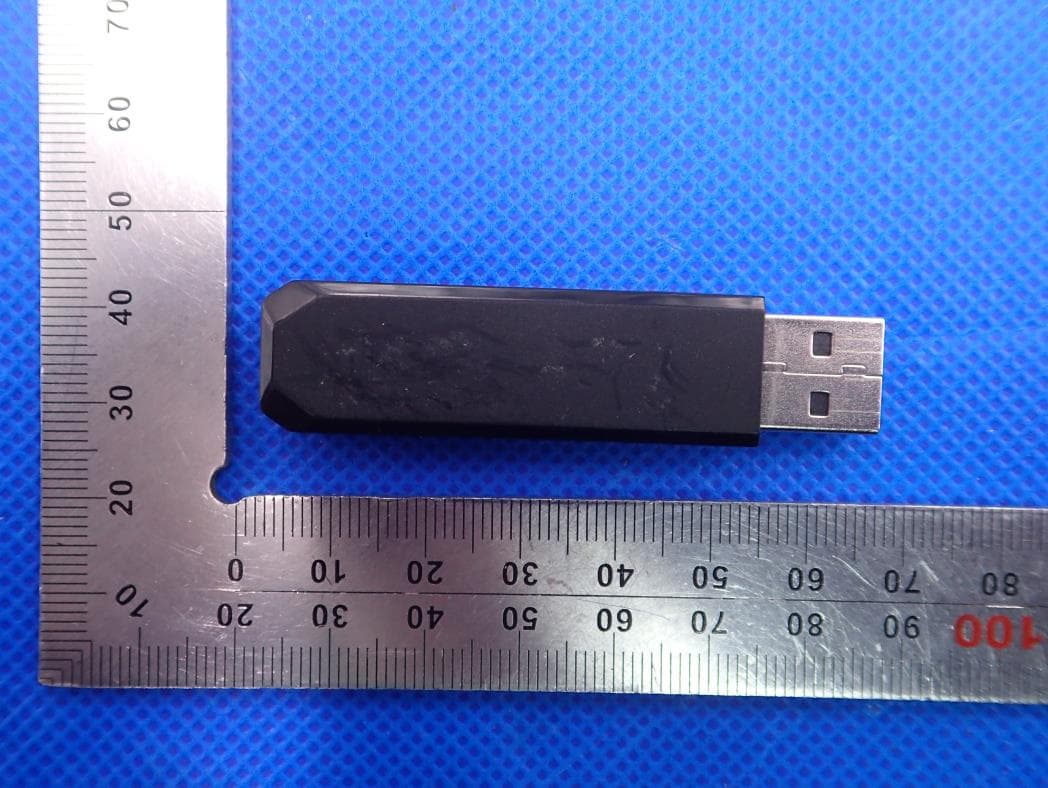
Click to zoom
Application Details
- Equipment Class
- DTS - Digital Transmission System
- Date of Grant
- Mar 01, 2020
- Application Purpose
- Original Equipment
- Date of Application
- Mar 01, 2020
- Equipment Note
- MH670 Dongle
- Frequency Range
- 2403.35000000 - 2479.35000000
- Country
- Taiwan
Documents & Files
Document Text
Text extracted from the exhibit documents filed with the FCC. Open a document above to read the original.
Users Manual
MAKE YOUR GAMING EXPERIENCE. Ver 2.0: 2019/09 512002921-GP © 2019 Cooler Master Technology Inc. All Rights Reserved. All t rademarks are registered to their respective owners. China - Cooler Master China 7th Floor, Building C, Hongqiao R&F Center, No.7, 958 Lane, Shenhong Road, Minhang District, Shanghai City 200051, China Tel: +86-21-51872177 Cooler Master Products : LIMITED WARRANTY This document describes the warranty terms for all Cooler Master peripheral products WHO THE WARRANTY PROTECTS: This Warranty is valid to the original purchaser only. WHAT THE WARRANTY PROTECTS: This warranty is valid only for the Cooler Master Products distributed by authorized dealer(s). Please contact Cooler Master for warranty information, services and questions: http://account.coolermaster.com WHAT IS AND IS NOT COVERED It is important to note that our warranty is not an unconditional guarantee for the duration of the Program. Any replaced parts become the property of Cooler Master. The Program does not apply to the software component of a product or a product which has been damaged due to accident, misuse, abuse, improper installation, usage not in accordance with product specifications and instructions, natural or personal disaster, or unauthorized alterations, repairs or modifications. The Program does also not cover any events such as below: • Any damages unrelated to manufacturing defects. • Any unsuitable environment or use of the product in Cooler Master Opinion. • Any product which has been modified without official permission from Cooler Master, or on which the serial number or warranty sticker has been defaced, modified, or removed. Damage, deterioration or malfunction resulting from: • Accident, abuse, misuse, neglect, fire, water, lightning, or other acts of nature, commercial or industrial use, unauthorized product modification or failure to follow instructions included with the product. • Third party products using Cooler Master Components will not be covered by warranty. See your vendor or the manufacturer for information about servicing. • Repair or attempted repair by anyone not authorized by Cooler Master, Inc. • Any shipment damages (claims must be made with the carrier). • Unauthorized repairs to a Cooler Master product will void the warranty offered by the Program. Cooler Master reserves the right to refuse to service any product which has been altered, modified or repaired by non-Cooler Master Service personnel. • Cooler Master does not warrant that this product will meet your requirements. It is your responsibility to determine the suitability of this product for your purpose. • Removal or installation charges. • You are responsible for the cost of shipping the product to Cooler Master. Cooler Master pays the cost of returning a product to You (applies only if product is directly purchased from Cooler Master). • Cooler Master reserves the right to replace the product with a service product at their sole discretion at any time. • Product malfunction or damage resulting from liquids or moisture. • All accessories that malfunction due to physical damage such as: USB cables, extension cables, adapter cables, adapters, power cords, screws, retention brackets, ear cups, and all other similar accessories. LIMITATION OF IMPLIED WARRANTIES: THERE ARE NO WARRANTIES, EXPRESS OR IMPLIED, WHICH EXTEND BEYOND THE DESCRIPTION CONTAINED HEREIN INCLUDING THE IMPLIED WARRANTY OF MERCHANTABILITY AND FITNESS FOR A PARTICULAR PURPOSE. For the most updated information please visit our official website: www.coolermaster.com Cooler Master Support: https://account.coolermaster.com EXCLUSION OF DAMAGES COOLER MASTER’S LIABILITY IS LIMITED TO THE COST OF REPAIR OR REPLACEMENT OF THE PRODUCT. COOLER MASTER SHALL NOT BE LIABLE FOR: • DAMAGE TO OTHER PROPERTY CAUSED BY ANY DEFECT IN THE PRODUCT, DAMAGES BASED UPON INCONVENIENCE, LOSS OF USE OF THE PRODUCT, LOSS OF TIME, LOSS OF PROFITS, LOSS OF BUSINESS OPPORTUNITY, LOSS OF GOODWILL, INTERFERENCE WITH BUSINESS RELATIONSHIPS OR OTHER COMMERCIAL LOSS, EVEN IF ADVISED OF THEIR POSSIBILITY OF SUCH DAM AGES. • ANY OTHER DAMAGES, WHETHER INCIDENTAL, CONSEQUENTIAL OR OTHERWISE • ANY CLAIM AGAINST THE CUSTOMER BY ANY OTHER PARTY WARRANTY INFORMATION: If the product is found with reasonable defect within the period of (refer to Table A.,) starting on the first day of purchase (with proof of invoice), this is what you must do, to claim warranty. PROCEDURES: 1. Consumers should return to the shop where he/she has bought the goods, After confirming with the shop with a valid invoice, they may approach the distributor for RMA claim. 2. After confirmed by the distributor that the goods was damaged due to natural causes, replacement and repair will be done by distributor (including brand new or refurbished goods) 3. All faulty goods must return to the distributor, expenses for returning the faulty goods will be covered by the consumer, and distributor will cover the cost involved in the transporting of parts or repaired goods to the consumer. Regarding all the expenses incurred in making the claim, and this is how you would claim: 1. Within the valid warranty date, starting from the first day of issuing invoice, Retail shops will assist in confirmation with distributor for the consumer for the following: A. If the damage was caused by the consumer, then the consumer should cover all expenses in fixing the product, if the product still can’t be fixed, we would suggest consumer in buying a brand new product. B. Product defect caused under natural use, expenses will be covered by the distributor. 2. Faulty products with expired warranty dates, we would suggest consumer to purchase a new products, without undergoing for repairs. Table A: Cooler Master Products Please check your user manual for the exact warranty period terms for products that are not shown below. For more warranty information, please visit our official website: http://www.coolermaster.com/service/warranty.html …
Text truncated - open the document above for the full version.
External Photos
External Photos TOP VIEW OF EUT BOTTOM VIEW OF EUT FRONT VIEW OF EUT BACK VIEW OF EUT LEFT VIEW OF EUT RIGHT VIEW OF EUT
ID Label/Location Info
FCC ID Label Location FCC ID: 2AR8X-MH670AWD
Internal Photos
Internal Photos OPEN VIEW OF EUT BATTERY VIEW OF EUT INTERNAL VIEW OF EUT-1 INTERNAL VIEW OF EUT-2 Antenna 1 Antenna 2 INTERNAL VIEW OF EUT-3 INTERNAL VIEW OF EUT-4
Operational Description
Declaration concerning Antenna Specification It is hereby declared that the product Model No.: MH-670-AWD FCC ID: 2AR8X-MH670AWD fulfills the requirement in FCC test relating to the antenna type. The device specified above confirms to the FCC recommendations for internal antenna type(s) described below: 1 Type of antenna: Ceramic Antenna Gain of the antenna: 0.4dBi Frequency range: 2.40335 GHz to 2.47935GHz 2 Type of antenna: Ceramic Antenna Gain of the antenna: 0.4dBi Frequency range: 2.40335 GHz to 2.47935GHz The mounting of the antenna is fixed to the radio module and no other antenna should be used. Company name: Cooler Master Technology Inc. Address: 8F., No788-1, Zhongzheng Rd., Zhonghe Dist., New Taipei City 23586,Taiwan Place: Taiwan Date: 2020-02-28 Signature:
RF Exposure Info
RF EXPOSURE EVALUATION 1. PRODUCT INFORMATION Product Description MH670 Dongle Model Name MH-670-AWD FCC ID 2AR8X-MH670AWD 2. EVALUATION METHOD According to 447498 D01 General RF Exposure Guidance v05 The 1-g and 10-g SAR test exclusion thresholds for 100 MHz to 6 GHz at test separation distances ≤ 50 mm are determined by: [(max. power of channel, including tune-up tolerance, mW)/(min. test separation distance, mm)] ·[√f(GHz)] ≤ 3.0 for 1-g SAR and ≤ 7.5 for 10-g extremity SAR. Where f(GHz) is the RF channel transmit frequency in GHz Power and distance are rounded to the nearest mW and mm before calculation 3. CALCULATION P t =2.997dBm=1.99mW The value of the Maximum output power P t is referred to the test report of the CFR47 §15.247. The result for RF exposure evaluation SAR=(1.99mW /5mm) .[√2.48(GHz)]= 0.63<3.0 for 1-g SAR and ≤ 7.5 for 10-g extremity SAR. 4. CONCLUSION The SAR evaluation is not required.
Test Report
Page 1 of 52 FCC Test Report Report No.: AGC01612200102FE02 FCC ID : 2AR8X-MH670AWD APPLICATION PURPOSE : Original Equipment PRODUCT DESIGNATION : MH670 Dongle BRAND NAME : COOLER MASTER MODEL NAME : MH-670-AWD APPLICANT : Cooler Master Technology Inc. DATE OF ISSUE : Jan. 17, 2020 STANDARD(S) : FCC Part 15.247 REPORT VERSION : V1.0 Attestation of Global Compliance (Shenzhen) Co., Ltd CAUTION: This report shall not be reproduced except in full without the written permission of the test laboratory and shall not be quoted out of context. Report No.: AGC01612200102FE02 Page 2 of 52 REPORT REVISE RECORD Report Version Revise Time Issued Date Valid Version Notes V1.0 / Jan. 17, 2020 Valid Initial Release Report No.: AGC01612200102FE02 Page 3 of 52 TABLE OF CONTENTS 1. VERIFICATION OF COMPLIANCE ............................................................................................................... 5 2.GENERAL INFORMATION ............................................................................................................................. 6 2.1PRODUCT DESCRIPTION ........................................................................................................................ 6 2.2. TABLE OF CARRIER FREQUENCYS ..................................................................................................... 6 2.3 RELATED SUBMITTAL(S)/GRANT(S) ..................................................................................................... 8 2.4TEST METHODOLOGY ............................................................................................................................ 8 2.5 SPECIAL ACCESSORIES ........................................................................................................................ 8 2.6 EQUIPMENT MODIFICATIONS ............................................................................................................... 8 3. MEASUREMENT UNCERTAINTY ................................................................................................................. 9 4. DESCRIPTION OF TEST MODES ............................................................................................................... 10 5. SYSTEM TEST CONFIGURATION ............................................................................................................. 11 5.1 CONFIGURATION OF TESTED SYSTEM ............................................................................................... 11 5.2 EQUIPMENT USED IN TESTED SYSTEM .............................................................................................. 11 5.3. SUMMARY OF TEST RESULTS ............................................................................................................. 11 6. TEST FACILITY ........................................................................................................................................... 12 7. PEAK OUTPUT POWER ............................................................................................................................. 13 7.1. MEASUREMENT PROCEDURE ........................................................................................................... 13 7.2. TEST SET-UP (BLOCK DIAGRAM OF CONFIGURATION) .................................................................. 13 7.3. LIMITS AND MEASUREMENT RESULT ............................................................................................... 14 8. 6 DB BANDWIDTH ...................................................................................................................................... 18 8.1. MEASUREMENT PROCEDURE ........................................................................................................... 18 8.2. TEST SET-UP (BLOCK DIAGRAM OF CONFIGURATION) .................................................................. 18 8.3. LIMITS AND MEASUREMENT RESULTS ............................................................................................. 18 9. CONDUCTED SPURIOUS EMISSION ........................................................................................................ 20 9.1. MEASUREMENT PROCEDURE ........................................................................................................... 20 9.2. TEST SET-UP (BLOCK DIAGRAM OF CONFIGURATION) .................................................................. 20 9.3. MEASUREMENT EQUIPMENT USED .................................................................................................. 20 9.4. LIMITS AND MEASUREMENT RESULT ............................................................................................... 20 10. MAXIMUM CONDUCTED OUTPUT POWER SPECTRAL DENSITY ....................................................... 25 Report No.: AGC01612200102FE02 Page 4 of 52 10.1 MEASUREMENT PROCEDURE .......................................................................................................... 25 10.2 TEST SET-UP (BLOCK DIAGRAM OF CONFIGURATION) ................................................................. 25 10.3 MEASUREMENT EQUIPMENT USED ................................................................................................. 25 10.4 LIMITS AND MEASUREMENT RESULT .............................................................................................. 25 11. RADIATED EMISSION ............................................................................................................................... 29 11.1. MEASUREMENT PROCEDURE ......................................................................................................... 29 11.2. TEST SETUP ....................................................................................................................................... 30 11.3. LIMITS AND MEASUREMENT RESULT ............................................................................................. 31 11.4. TEST RESULT ...................................................…
Text truncated - open the document above for the full version.
Test Setup Photos
Test Setup Photos RADIATED EMISSION TEST SETUP BELOW 1GHZ RADIATED EMISSION TEST SETUP ABOVE 1GHZ CONDUCTED EMISSION TEST SETUP
Contact Information
Applicant
Monica Chiu(IO-CGP PM)
Test Firm
Attestation of Global Compliance (Shenzhen) Co., LDoris Li
[email protected]+86-755-25234088
Technical Specifications
| # | Rule Parts | Frequency Range | Power Output |
|---|---|---|---|
| 1 | 15C | 2.40 GHz - 2.48 GHz | 1.99 mW |
Other Applications from Cooler Master Technology Inc.
2AR8X-CH351
Aug 20, 2024Gaming Headset
Equipment Class
DSS - Part 15 Spread Spectrum Transmitter2AR8X-CMHS-D
Aug 20, 2024Dongle
Equipment Class
DTS - Digital Transmission System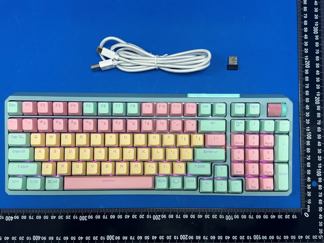
2AR8X-MK770MCKR1US
Jul 15, 2023MK770
Equipment Class
DSS - Part 15 Spread Spectrum Transmitter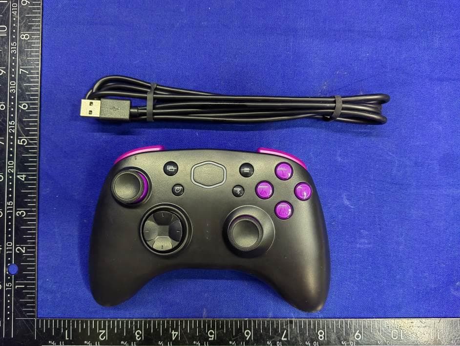
2AR8X-CMSCBT
Feb 26, 2023Storm Gaming Controller
Equipment Class
DSS - Part 15 Spread Spectrum Transmitter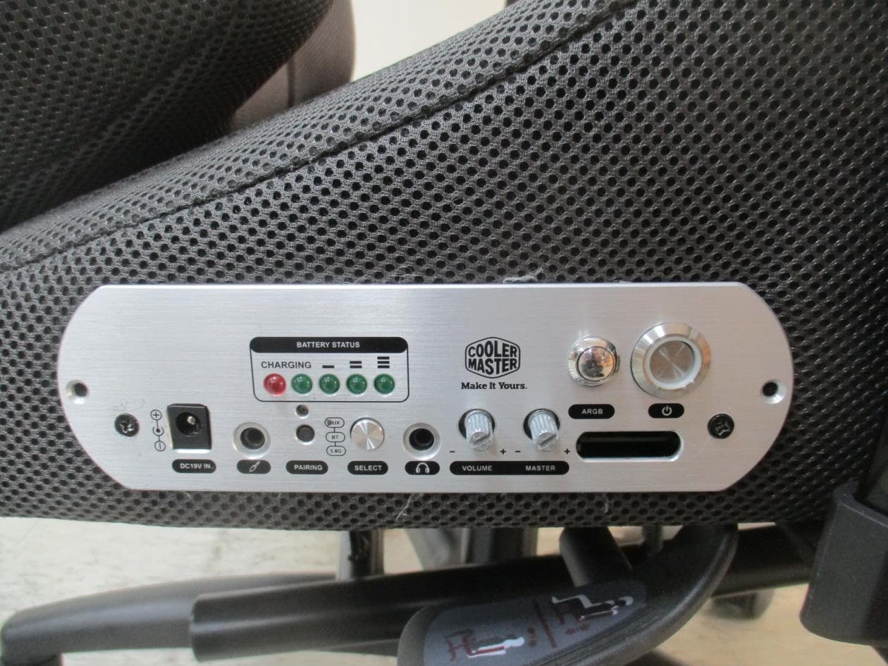
2AR8X-IXC-SX1
Jan 04, 2023Synk X
Equipment Class
DSS - Part 15 Spread Spectrum Transmitter