2ARDMEDC18DEDC18D
ShenZhen Easydetek Technology CO. LTD.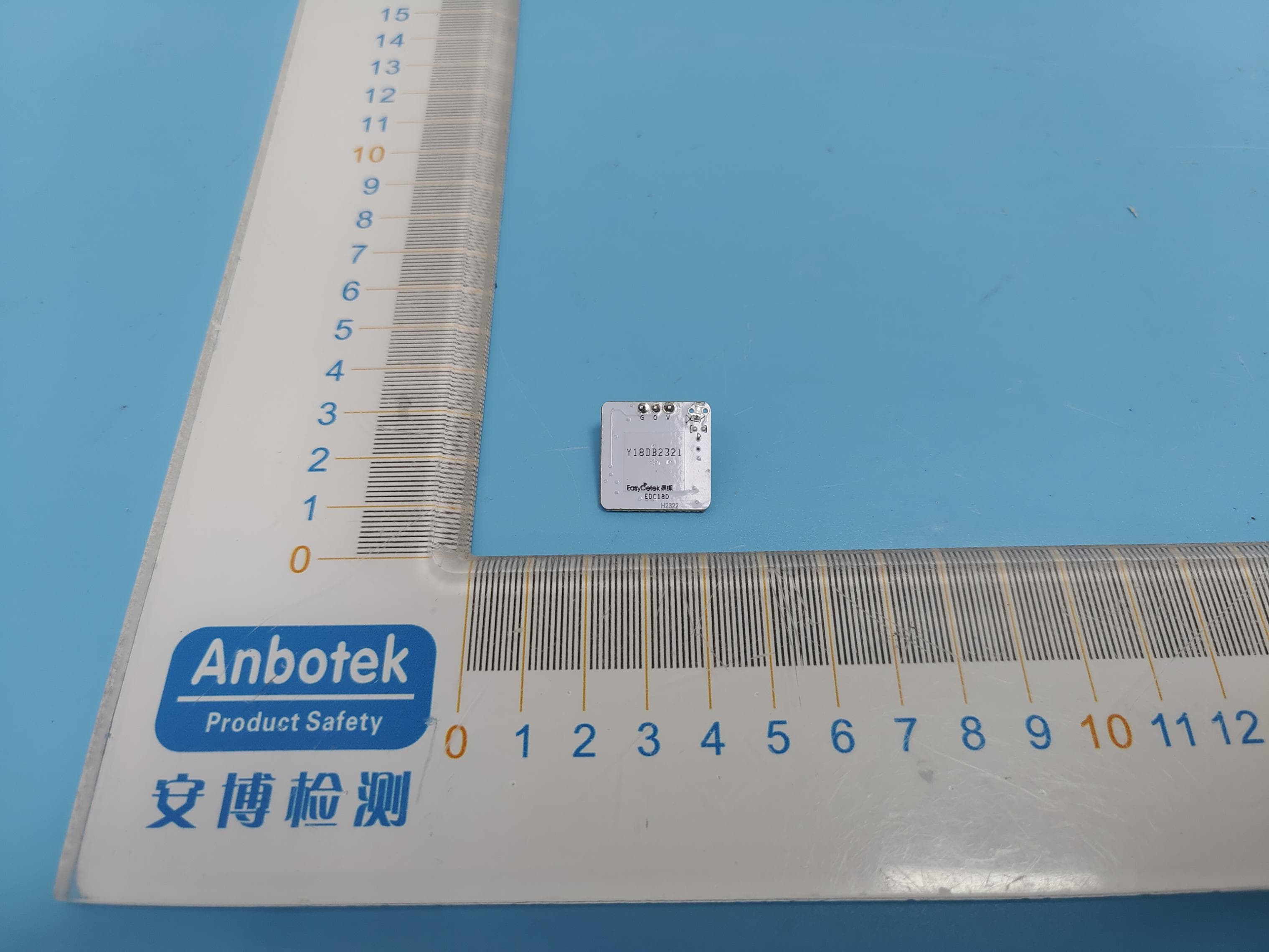
Click to zoom
Application Details
- Equipment Class
- DXX - Part 15 Low Power Communication Device Transmitter
- Date of Grant
- Mar 12, 2024
- Application Purpose
- Original Equipment
- Date of Application
- Feb 20, 2024
- Equipment Note
- EDC18D
- Frequency Range
- 5750.00000000 - 5870.00000000
- Country
- China
Documents & Files
Document Text
Text extracted from the exhibit documents filed with the FCC. Open a document above to read the original.
Users Manual
Shenzhen EasyDetek Technology Co.,Ltd EDC18D - 1 - Address: Room 402, Building B, Hangcheng Industrial Zone, Chentian, Xixiang Street, Baoan District, Shenzhen Phone: 0755-27788421 e-mail:[email protected] Manual (Model: EDC18D) 1. Product Description The EDC18D module designed based on the 5.8GHz Ultra Low Power Microwave Radar Induction Chip AT58LP1T1DB. This chip is based on the principle of Doppler effect development, using mature CMOS technology, highly integrated microwave transceiver, IF signal processing and filtering on one chip. Because the adaptive calibration algorithm is integrated on chip, the problems of in-band interference, out-of-band blocking and environmental interference are effectively solved, and the reliability and practicability of the sensor are greatly improved. The EDC18D module is powered by the TM56M1511 power manage chip, and the microwave signal generated by the PLL inside the RF-IC (AT58LP1T1DB) is amplified by PA and radiated out through the ANT-TX antenna. The microwave signal will reflect when it encounters an object in the air. When the object is in motion, there is a certain frequency difference between the reflected signal and the transmitted signal. The reflected signal received by the ANT-RX is mixed with the transmitted signal to obtain the corresponding intermediate frequency information. MCU processes and analyzes the intermediate frequency signal, while MCU also continuously detects the CDS signal. Finally, the MCU determines the CDS signal and IF signal for final OUT output control. EDC18D 2. Product Advantage ■ CE-RED/FCC certified to meet new ERP requirements ■ Simplified solution with integrated IC, simple wiring ■ Hanging height within 3.5m, sensing radius within 3m ■ Size: 20mm x 20mm ■ Suitable for all kinds of scenes below 18W and short sensing distance ■ Low price, high cost performance Shenzhen EasyDetek Technology Co.,Ltd EDC18D - 2 - Address: Room 402, Building B, Hangcheng Industrial Zone, Chentian, Xixiang Street, Baoan District, Shenzhen Phone: 0755-27788421 e-mail:[email protected] 3. Electrical Performance Transmit frequency 5750~5870MHz Input voltage DC 5V Output high level DC 3.3V Output low level < DC 0.5 V 3db beam angle 97°(XZ plane) 99°(YZ plane) Working current 12-16mA Transmit power 0dBm Sensing distance 2-4m Delay time 30s±10% Operating temperature -20...﹢85°C Storage temperature -20...﹢105°C Remarks: 1. The test distance range is based on the module hanging height 3m, indoor testing environment. The tester's height is 170cm, the weight is 65-75kg, and the walking speed is 1m/s (2 steps per second). Different installation scenarios may cause range changes. Subject to actual test. 2. Due to the spectral characteristics of the photosensitive device, the threshold is uniformly tested under natural light conditions. 3. The delay time can be customized according to customer needs, with a delay tolerance of ±10%. 4. This product is suitable for scenarios where the installation height is less than 4m. If the installation height is greater than 4m, extreme conditions such as inability to sense may occur. If you need to exceed this height, please contact the relevant technical personnel. 4. Product block diagram EDC18D module block diagram Shenzhen EasyDetek Technology Co.,Ltd EDC18D - 3 - Address: Room 402, Building B, Hangcheng Industrial Zone, Chentian, Xixiang Street, Baoan District, Shenzhen Phone: 0755-27788421 e-mail:[email protected] EDC18D pin definition 5. Product antenna dimensions and pictures Antenna type: PCB antenna Antenna size: 11mm*11mm 6. Pin Description Pin Description GND Ground OUT Output signal/support PWM VCC 5V power supply Shenzhen EasyDetek Technology Co.,Ltd EDC18D - 4 - Address: Room 402, Building B, Hangcheng Industrial Zone, Chentian, Xixiang Street, Baoan District, Shenzhen Phone: 0755-27788421 e-mail:[email protected] 7. Product Circuit Schematic 8. Typical Application Bulb light Ceiling light Down light *The above are typical application products, more products can be expanded. Shenzhen EasyDetek Technology Co.,Ltd EDC18D - 5 - Address: Room 402, Building B, Hangcheng Industrial Zone, Chentian, Xixiang Street, Baoan District, Shenzhen Phone: 0755-27788421 e-mail:[email protected] 9. Product Size Chart EDC18D dimensional tolerance: ±0.2mm (Pin welding hole: φ0.9mm tolerance: ±0.05mm) 10. Timing Diagram 11. Detection Diagram Ceiling Installation Diagram Shenzhen EasyDetek Technology Co.,Ltd EDC18D - 6 - Address: Room 402, Building B, Hangcheng Industrial Zone, Chentian, Xixiang Street, Baoan District, Shenzhen Phone: 0755-27788421 e-mail:[email protected] 12. Function Description Photosensitive function is on. When the ambient light is bright enough, the light will not automatically light up even if a moving object is detected. When the ambient light is lower than the preset photosensitive threshold, the light will automatically light up when the sensor detects a moving object. After the moving object leaves, the sensor will enter the delay time when it cannot detect the moving object and keep the light on. Photosensitive function is off. After the preset delay time, the light will automatically turn off. If no moving objects can be detected, and the lamp goes out. After the delay time, when the sensor cannot detect any moving objects, the lamp will be off. When the sensor detects a moving object, the light automatically lights up at 100% brightness and enters the preset delay time. Shenzhen EasyDetek Technology Co.,Ltd EDC18D - 7 - Address: Room 402, Building B, Hangcheng Industrial Zone, Chentian, Xixiang Street, Baoan District, Shenzhen Phone: 0755-27788421 e-mail:[email protected] 【hardware】: 【software】: ED ED Frequency section C S 3GHz Product categories Product subdivision Product Number D Time delay 30 Y Serial number F 6GHz 1 Microwave sensor module 2. Microwave radar switch 3 Radar antenna 0 Ultra-low-power series 1 Flagship series RC 5.8GHz 2 Short-distance series RY Has …
Text truncated - open the document above for the full version.
Attestation Statements
TheinformationprovidedinthisletterisbasedonthereferencedrulepartsofTitle47oftheCFRaswellasKDB986446D01. ShenZhenEasydetekTechnologyCO.LTD. FederalCommunicationsCommission AuthorizationandEvaluationDivision EquipmentAuthorizationBranch 7435OaklandMillsRoad Columbia,MD21046 10/7/23 Towhomitmayconcern: We,[ShenZhenEasydetekTechnologyCO.LTD.],herebycertifythattheequipmentforwhich authorizationissought(FCCID:2ARDMEDC18D)isnot“covered”equipmentprohibitedfrom receivinganequipmentauthorizationpursuantto§2.903oftheFCCrules. Wealsocertifythat,asofthedateofthefilingoftheapplication,wearenotidentifiedontheCovered List(https://www.fcc.gov/supplychain/coveredlist)asanentityproducing“covered”equipment. Bysigningthisform,weconfirmtheaboveandthatweareawareoftheapplicationrequirements listedunder§2.911(b)and(d)(5)and(6). Sincerely, Signature [TobyLi] [GeneralManager] [ShenZhenEasydetekTechnologyCO.LTD.] 6 2 _ [ m o d e l ] C o v e r e d E q u _ 2 . 9 1 1 ( d ) ( 5 ) ( i ) a n d ( i i ) - U , V 0 2
Cover Letter(s)
FCC limited Modular Approval Request To the FCC or FCC TCB handling this application Hereby we, Company (grantee) ShenZhen Easydetek Technology CO. LTD. Addresss 6/F Fuyuan Industrial&commercial Building, Hangcheng Industrial Park, Baoan District, Shenzhen, 518000, China City / ZIP / State / Country China request limited modular approval for the certification of our equipment within this application, identified by: FCC ID: 2ARDMEDC18D The table below contains justification for modular approval of this equipment. Requirement per DA 00-1407 Explanation from grantee 1. The modular transmitter must have its own RF shielding. No RF shielding. Every host integrator is required to abtain a Class 2 permissive Change. The modular transmitter must have buffered modulation/data inputs (if such inputs are provided) to ensure that the module will comply with Part 15 requirements under conditions of excessive data rates or over-modulation. The modular have buffered modulation/data inputs. 2. The modular transmitter must have its own power supply regulation. The modular transmitter have its own power supply regulation.(DC 5-12V) The modular transmitter must comply with the antenna requirements of Section 15.203 and 15.204(c). The antenna must either be permanently attached or employ a “unique” antenna coupler (at all connections between the module and the antenna, including the cable).. The model number of the replaceable antenna is specified in the manual. 3. The modular transmitter must be tested in a stand-alone configuration, i.e., the module must not be inside another device during testing. This is intended to demonstrate that the module is capable of complying with Part 15 emission limits regardless of the device into which it is eventually installed. The module was tested in a stand-alone configuration, please refer to the Setup Photo for the detail 4. The modular transmitter must be labeled with its own FCC ID number, and, if the FCC ID is not visible when the module is installed inside another device, then the outside of the device into which the module is installed must also display a label referring to the enclosed module. This exterior label can use wording such as the following: “Contains Transmitter Module FCC ID: 2ARDMEDC18D” or “Contains FCC ID: 2ARDMEDC18D.” Any similar wording that expresses the same meaning may be used. The Grantee may either provide such a label, an example of which must be included in the application for equipment authorization, or, must provide adequate instructions along with the module which explain this requirement. In the latter case, a copy of these instructions must be included in the application for equipment authorization. Please refer to label sample exhibit - host labeling is described in integration manual 5. The modular transmitter must comply with any specific rule or operating requirements applicable to the transmitter and the manufacturer must provide adequate instructions along with the module to explain any such requirements. A copy of these instructions must be included in the application for equipment authorization. For example, there are very strict operational and timing requirements that must be met before a transmitter is authorized for operation under Section 15.231. For instance, data transmission is prohibited, except for operation under Section 15.231(e), in which case there are separate field strength level and timing requirements. Compliance with these requirements must be assured. The required FCC rule has been fulfilled and all the instructions for the maintaining compliance have been clearly stated in the User Manual. 6. The modular transmitter must comply with any applicable RF exposure requirements. For example, FCC Rules in Sections 2.1091, 2. 1093 and specific Sections of Part 15, including 15.319(i), 15.407(f), 15.253(f) and 15.255(g), require that Unlicensed PCS, UNII and millimetre wave devices perform routine environmental evaluation for RF Exposure to demonstrate compliance. In addition, spread spectrum transmitters operating under Section 15.247 are required to address RF Exposure compliance in accordance with Section 15.247(b)(4). Modular transmitters approved under other Sections of Part 15, when necessary, may also need to address certain RF Exposure concerns, typically by providing specific installation and operating instructions for users, installers and other interested parties to ensure compliance. The MPE evaluation with 20cm distance restriction is submitted for the compliance of RF Exposure requirement. Attestation (by grantee) City and Country: Date: Name: (this must be a person) Function: Signature: (or official company stamp) Shenzhen /China 2023-10-07 Toby Li General Manager
External Photos
ProjectNo.:18220WC301846Page1of1 Code:AB-RF-05-b AppendixII--ExternalPhotograph
ID Label/Location Info
LabelLocationOnEUT Label : FCCID:2ARDMEDC18D
Internal Photos
ProjectNo.:18220WC301846Page1of2 Code:AB-RF-05-b AppendixIII--InternalPhotograph ProjectNo.:18220WC301846Page2of2 Code:AB-RF-05-b ANT
RF Exposure Info
MAXIMUMPERMISSIBLEEXPOSURE KDB447498D01MobileandPortableDevicesRFExposureProceduresand EquipmentAuthorizationPoliciesv06. AccordingtoFCC1.1310:Thecriterialistedinthefollowingtableshallbeused toevaluatetheenvironmentimpactofhumanexposuretoradiofrequency(RF) Radiationasspecifiedin§1.1307(b) FCCID:2ARDMEDC18D EUTSpecification EUTEDC18D Frequencyband (Operating) WLAN:2.412GHz~2.462GHz WLAN:5.18GHz~5.32GHz/5.50GHz~5.70GHz WLAN:5.745GHz~5825GHz Others:5750~5870MHz DevicecategoryPortable(<20cmseparation) Mobile(>20cmseparation) Others___ ExposureclassificationOccupational/Controlledexposure GeneralPopulation/Uncontrolledexposure AntennadiversitySingleantenna Multipleantennas Txdiversity Rxdiversity Tx/Rxdiversity Max.outputpower95.55dBuV/m(0.292dBm) Antennagain(Max)4.86dBi EvaluationappliedMPEEvaluation SAREvaluation LimitsforMaximumPermissibleExposure(MPE) Frequency Range(MHz) ElectricField Strength(V/m) MagneticField Strength(A/m) PowerDensity (mW/cm 2 ) AverageTime (A)LimitsforOccupational/ControlExposures 300-1500----F/3006 1500-100000----56 (B)LimitsforGeneralPopulation/UncontrolExposures 300-1500----F/150030 1500-100000----130 Friistransmissionformula:Pd=(Pout*G)\(4*pi*R2) Where Pd=PowerdensityinmW/cm 2 Pout=outputpowertoantennainMw G=gainofantennainlinearscale Pi=3.1416 R=distancebetweenobservationpointandcenteroftheradiatorincm PdthelimitofMPE.Ifweknowthemaximumgainoftheantennaandtotal powerinputtotheantenna,throughthecalculation,wewillknowthedistance wheretheMPElimitisreached. MeasurementResult EIRP=E-104.8+20logD=95.55-104.8+20log3=0.292dBm Operating Mode Maximum output power (dBm) Tuneup tolerance (dBm) Max.Tuneup Power (dBm) Antenna Gain (dBi) Power densityat 20cm (mW/cm 2 ) Power density Limits (mW/cm 2 ) 5.8G0.2920.292±1 1.292 4.860.00081 Result:NoStandaloneSARtestisrequired.
Test Report
ReportNo.:18220WC30184601FCCID:2ARDMEDC18DPage1of29 Code:AB-RF-05-b FCCTestReport Applicant:ShenZhenEasydetekTechnologyCO.LTD. Address: 6/FFuyuanIndustrial&commercialBuilding, HangchengIndustrialPark,BaoanDistrict, Shenzhen,518000,China ProductName:EDC18D ReportDate:Sept.27,2023 ShenzhenAnbotekComplianceLaboratoryLimited ReportNo.:18220WC30184601FCCID:2ARDMEDC18DPage2of29 Code:AB-RF-05-b Contents 1.GeneralInformation ............................................................................................................................................5 1.1.ClientInformation ....................................................................................................................................5 1.2.DescriptionofDevice(EUT) ..................................................................................................................5 1.3.AuxiliaryEquipmentUsedDuringTest .................................................................................................6 1.4.DescriptionofTestConfiguration ..........................................................................................................6 1.5.DescriptionofTestSetup .......................................................................................................................7 1.6.TestEquipmentList .................................................................................................................................8 1.7.MeasurementUncertainty ......................................................................................................................9 1.8.DescriptionofTestFacility .....................................................................................................................9 1.9.Disclaimer ...............................................................................................................................................10 2.SummaryofTestResults .................................................................................................................................11 3.ConductedEmissionTest ................................................................................................................................12 3.1.TestStandardandLimit ........................................................................................................................12 3.2.TestSetup ...............................................................................................................................................12 3.3.TestProcedure .......................................................................................................................................12 3.4.TestData .................................................................................................................................................12 4.RadiatedEmissionandBandEdge ...............................................................................................................15 4.1.TestStandardandLimit ........................................................................................................................15 4.2.TestSetup ...............................................................................................................................................16 4.3.TestProcedure .......................................................................................................................................17 4.4.TestData .................................................................................................................................................18 5.20dBBandwidthTest ........................................................................................................................................25 5.1.TestStandardandLimit ........................................................................................................................25 5.2.TestSetup ...............................................................................................................................................25 5.3.TestProcedure .......................................................................................................................................25 5.4.TestData .................................................................................................................................................25 6.AntennaRequirement ......................................................................................................................................28 6.1.TestStandardandRequirement .........................................................................................................28 6.2.AntennaConnectedsConstruction .....................................................................................................28 APPENDIXI--TESTSETUPPHOTOGRAPH ................................................................................................29 APPENDIXII--EXTERNALPHOTOGRAPH ..................................................................................................29 APPENDIXIII--INTERNALPHOTOGRAPH ...................................................................................................29 ReportNo.:18220WC30184601FCCID:2ARDMEDC18DPage3of29 Code:AB-RF-05-b TESTREPORT Applicant:ShenZhenEasydetekTechnologyCO.LTD. Manufacturer:ShenZhenEasydetekTechnologyCO.LTD. ProductName:EDC18D TestModelNo.:EDC18D ReferenceModelNo.:N/A TradeMark:N/A Rating(s):Input:DC5-12V TestStandard(s): FCCPart15SubpartC,Paragraph15.249 TestMethod(s): ANSIC63.10:2020 ThedevicedescribedaboveistestedbyShenzhenAnbotekComplianceLaboratoryLimitedto determinethemaximumemissionlevelsemanatingfromthedeviceandtheseverelevelsofthedevice canendureanditsperformancecriterion.Themeasurementresultsarecontainedinthistestreportand ShenzhenAnbotekComplianceLaboratoryLimitedisassumedfullofresponsibilityfortheaccuracy andcompletenessofthesemeasurements.Also,thisreportshowsthattheEUT(EquipmentUnder Test)ist…
Text truncated - open the document above for the full version.
Test Report
version01 ShenZhenEasydetekTechnologyCO.LTD. DeclarationconcerningAntennaSpecification Itisherebydeclaredthattheproduct ModelNo.:EDC18D FCCID:2ARDMEDC18D fulfillstherequirementinFCCtestrelatingtotheantennatype. ThedevicespecifiedaboveconfirmstotheFCCrecommendationsforinternalantennatype(s) describedbelow: ModelNo.ofantenna:EDC18D Typeofantenna:PCBantenna Gainoftheantenna:4.86dbi Frequencyrange:5750~5870MHz Themountingoftheantennaisfixedtotheradiomoduleandnootherantennashouldbeused. Companyname: ShenZhenEasydetekTechnologyCO.LTD. Address:6/FFuyuanIndustrial&commercialBuilding,HangchengIndustrialPark, BaoanDistrict,Shenzhen,518000,China City:Shenzhen ZIP/Postalcode:/ Country:China Place:ShenzhenDate:10/7/2023 Signature:
Test Report
正直、专业、创新、超越 深圳市易探科技有限公司 文件编码: EDCT23004 机密等级:B 报告版次:A Antennareport-EDC18D 1.Type of antenna:PCB antenna 2.Antenna size map Antenna Metal Patch: 11*11mm Antenna GND:20*20mm 1. 2D/3Dgain map 正直、专业、创新、超越 2.2D/3Dsimulationdatasheet S11:[email protected] MHzdBi 5750 H4.74 V-2.09 5800 H4.79 V-1.73 5870 H4.86 V-2.6 正直、专业、创新、超越 易探科技 http://www.easydetek.com/ 电话:0755-2778-8421 邮箱:[email protected] 地址:深圳市宝安区西乡街道臣田航城工业区A2栋401
Test Setup Photos
ProjectNo.:18220WC301846Page1of2 Code:AB-RF-05-b AppendixI--TestSetupPhotograph ConductedEmissionatACpowerline PhotoofRadiationEmissionTest(below1GHz) ProjectNo.:18220WC301846Page2of2 Code:AB-RF-05-b PhotoofRadiationEmissionTest(above1GHz)
Contact Information
Applicant
Toby Li(General Manager)
Test Firm
Shenzhen Anbotek Compliance Laboratory LimitedJeff Zhu
[email protected]13798230942
Technical Specifications
| # | Rule Parts | Frequency Range | Power Output |
|---|---|---|---|
| 1 | 15C | 5.75 GHz - 5.87 GHz | 1.10 mW |
Other Applications from ShenZhen Easydetek Technology CO. LTD.
2ARDMEDC211D
Jan 27, 2021Microwave
Equipment Class
DXT - Part 15 Low Power Transceiver, Rx Verified