2ARDMEDC211DMicrowave
ShenZhen Easydetek Technology CO. LTD.Application Details
- Equipment Class
- DXT - Part 15 Low Power Transceiver, Rx Verified
- Date of Grant
- Jan 27, 2021
- Application Purpose
- Original Equipment
- Date of Application
- Jan 27, 2021
- Equipment Note
- Microwave
- Frequency Range
- 5730.00000000 - 5870.00000000
- Country
- China
Documents & Files
Document Text
Text extracted from the exhibit documents filed with the FCC. Open a document above to read the original.
Users Manual
Address:Room601,BuildingA2,HangchengIndustrialZone,Chentian,XixiangStreet,BaoanDistrict,Shenzhen Tel:0755-2778-8421 Website:http://www.easydetek.com/ EDC211D -1- EDC211D-A EDC211D-B ■Theshellismadeofflame-retardantmaterials,withafireratingofV-0; ■Patentedantennadesign,superanti-interference;digitalradarchip,good consistency; ■Notaffectedbytemperature,humidity,airflow,dust,noise,brightness,etc.; ■ThebatchmeetstherequirementsofEN300440andEN301489standards; ■Meetenvironmentalprotectionrequirements. Features Address:Room601,BuildingA2,HangchengIndustrialZone,Chentian,XixiangStreet,BaoanDistrict,Shenzhen Tel:0755-2778-8421 Website:http://www.easydetek.com/ EDC211D -2- EDC211Dtypicalapplication CeilinglightPanelLightThreeanti-lightHighbaylights *Theabovearetypicalapplicationproducts,andmoreproductscanbeexpanded Transmitfrequency5.8GHz±15MHz Loadpower <400W@100V-240V OperatingVoltageAC100-240VEDC211D-A/EDC211D-B 3dbbeamangle93°(XZplane)99°(YZplane) Standbypowerconsumption <0.5W Sensingdistance3.5-6m Delaytime5s Photosensitivethreshold25Lux Antennagain4dB Operatingtemperature-20...+70°C storagetemperature-20...+105°C Remarks:1.Thetestdistancerangeisbasedonthemodulehangingheight3m, indoorenvironmenttest,thetester'sheightis170cm,theweightis65-75kg,and thewalkingspeedis1m/s(2stepspersecond).Differentinstallationscenariosmay causerangechanges.Subjecttoactualtest; 2.Duetothespectralcharacteristicsofthephotosensitivedevice,thethresholdis uniformlytestedundernaturallightconditions; 3.Thedelaytimecanbecustomizedaccordingtocustomerneeds,withadelay toleranceof±10%. ModelFunctiondescriptionInputvoltage EDC211D-AFour-positionadjustmentdialcode100-240Vinput EDC211D-BInfraredremotecontroladjustment100-240Vinput Typicalapplicationproducts Electricalproperties Productinformation Address:Room601,BuildingA2,HangchengIndustrialZone,Chentian,XixiangStreet,BaoanDistrict,Shenzhen Tel:0755-2778-8421 Website:http://www.easydetek.com/ EDC211D -3- EDC211D-APin PinDescription L-outFirewireout N-outZerolineout L-inFirewirein N-inZerolinein EDC211D-BPin PinDescription L-outFirewireout N-outZerolineout L-inFirewirein N-inZerolinein Pindescription Address:Room601,BuildingA2,HangchengIndustrialZone,Chentian,XixiangStreet,BaoanDistrict,Shenzhen Tel:0755-2778-8421 Website:http://www.easydetek.com/ EDC211D -4- Firstplace:Sensingdistancesetting 1 100%ON 50%- Accordingtodifferentapplications,thesensingdistancecanbeadjustedbythecode switchtoset100%,50% Secondandthirddigits:delaytimesetting 23 5sONON 1minON- 3min-0N 5min-- Delaytimereferstothetimethatthelightisonafterthemovingobjectleavesthe sensingarea.Thegearscanbeset:5s,1min,3min,5min Fourthplace:photosensitivethresholdsetting 4 25LuxON Disable- Whentheambientilluminancevalueislowerthanthesetvalve,anobjectmovesin thesensingarea.Stallsare:25Lux/allday DIPswitchsettings Address:Room601,BuildingA2,HangchengIndustrialZone,Chentian,XixiangStreet,BaoanDistrict,Shenzhen Tel:0755-2778-8421 Website:http://www.easydetek.com/ EDC211D -5- EDC211D-Aunit:(mm) Productsizechart Infraredremotecontrolsettings 100%:thefarthestdistance 75%:fartheraway 50%:closer 25%:shortdistance 10s:selecttime10s 30s:selectthetime30s 1min:selecttime1min Turnonthephotosensitivefunction Turnoffthephotosensitivefunction 30Lux 15Lux Address:Room601,BuildingA2,HangchengIndustrialZone,Chentian,XixiangStreet,BaoanDistrict,Shenzhen Tel:0755-2778-8421 Website:http://www.easydetek.com/ EDC211D -6- EDC211D-Bunit:(mm) Photosensitivefunctionison FunctionDescription Whentheambientlightisbrightenough,thelightwillnot automaticallylightupevenifamovingobjectisdetected Whentheambientlightislowerthanthepreset photosensitivethreshold,thelightwillautomaticallylight upwhenthesensordetectsamovingobject Afterthemovingobjectleaves,thesensorwillenterthe delaytimewhenitcannotdetectthemovingobjectand Afterthepresetdelaytime,thelightwillautomaticallyturnoff Address:Room601,BuildingA2,HangchengIndustrialZone,Chentian,XixiangStreet,BaoanDistrict,Shenzhen Tel:0755-2778-8421 Website:http://www.easydetek.com/ EDC211D -7- Photosensitivefunctionisoff Supportpackaging:BlisterpackagingBubblebagpackagingPEbagpackaging Nomovingobjectscanbedetected,andthelampgoes out Whenthesensordetectsamovingobject,thelight automaticallylightsupat100%brightnessandentersthe setdelaytime Afterthedelaytime,whenthesensorcannotdetect anymovingobjects,thelampwillbeoff PackagingInformation Address:Room601,BuildingA2,HangchengIndustrialZone,Chentian,XixiangStreet,BaoanDistrict,Shenzhen Tel:0755-2778-8421 Website:http://www.easydetek.com/ EDC211D -8- *Note:Thedistancecanbeadjustedaccordingtotheactualapplication Detectiondiagram Address:Room601,BuildingA2,HangchengIndustrialZone,Chentian,XixiangStreet,BaoanDistrict,Shenzhen Tel:0755-2778-8421 Website:http://www.easydetek.com/ EDC211D -9- 1.Theinstallationprocessoftheproductrequireskeepingtheantennaboardatacertain heightawayfromthemetalplane,andnotclosetoortouchingthemetalplane,otherwise theproductmaynotworknormally! 2.Avoidinstallingmetalaccessoriesorshells.Metalwillblockmicrowavesandaffectthe effect;therefore,thisproductshouldnotbeinstalledinametalshell.However,the penetrationeffectisbetterforobstaclessuchasplastic,ceramic,andwoodsoil; 3.Theoutputcurrentofthesensorisveryweak.Excessivecurrentdrivingislikelytocause falsealarms.Theloadcanbedrivenbyisolationdriving,ortheMCUcanbeusedtoreadthe outputportstatus; 4.Whenmultiplesensorsareusedinthesamesite,itisrecommendedthattheproduct installationdistancebegreaterthan1.5m.Toocloseinstallationdistancemaycausefalse alarmsinindividualcycles; 5.Theantennasurfaceshouldbeprotectedfromhighcurrentcircuitcoverage,whichmay causeinterference. RevisionDateDescriptionRemarks V1.02021-01-04-- ED ED Frequency band C ProductCategory 2 Product number 11 Antenna type D Characteristic - Delaytime 5Y Customer Number 1A Configuration 1 S3GHz F6GHz C5.8GHz Q24GHz V60GHz W77GHz 1Microwave sensor 2Microwave sensorswitch 3radarantenna 4MCU 5Microwave powersupply 6IC 7other 8networking SOnboard an…
Text truncated - open the document above for the full version.
External Photos
Report No.: 2007RSU072-UE 1 of 3 EUT External Photo (1) EUT Photo (2) EUT Photo Report No.: 2007RSU072-UE 2 of 3 (3) EUT Photo (4) EUT Photo Report No.: 2007RSU072-UE 3 of 3 (5) EUT Photo (6) EUT Photo
Internal Photos
Report No.: 2007RSU072-UE 1 of 4 EUT Internal Photo (1) EUT Photo (2) EUT Photo Report No.: 2007RSU072-UE 2 of 4 (3) EUT Photo (4) EUT Photo Report No.: 2007RSU072-UE 3 of 4 (5) EUT Photo (6) EUT Photo Report No.: 2007RSU072-UE 4 of 4 (7) EUT Photo
Test Report
MRT Technology (Suzhou) Co., Ltd Report No.: 2007RSU072-U1 Phone: +86-512-66308358 Report Version: V01 Web: www.mrt-cert.com Issue Date: 01-27-2021 Page Number: 1 of 44 FCC ID: 2ARDMEDC211D Application: ShenZhen Easydetek Technology CO. LTD. Application Type: Certification Product: Microwave Model No.: EDC211D-A Serial Model No.: EDC211D-X (“X” means A-Z) Brand Name: Easy Detek FCC Classification: Part 15 low power transceiver, RX verified (DXT) FCC Rule Part(s): Part 15.249 Test Procedure(s): ANSI C63.10 - 2013 Test Date: December 16, 2020 ~ January 26, 2021 MEASUREMENT REPORT FCC PART 15.249 Reviewed By: Vincent Yu Approved By: Robin Wu The test results relate only to the samples tested. This equipment has been shown to be capable of compliance with the applicable technical standards as indicated in the measurement report and was tested in accordance with the measurement procedures specified in ANSI C63.10-2013. Test results reported herein relate only to the item(s) tested. The test report shall not be reproduced except in full without the written approval of MRT Technology (Suzhou) Co., Ltd. Report No.: 2007RSU072-U1 2 of 44 Revision History Report No. Version Description Issue Date Note 2007RSU072-U1 Rev. 01 Initial Report 01-27-2021 Valid Report No.: 2007RSU072-U1 3 of 44 CONTENTS Description Page 1. GENERAL INFORMATION ........................................................................................................ 5 1.1. Applicant .......................................................................................................................... 5 1.2. Manufacturer ................................................................................................................... 5 1.1. Testing Facility ................................................................................................................. 5 2. PRODUCT INFORMATION ........................................................................................................ 6 2.1. Equipment Description .................................................................................................... 6 2.2. Frequency List ................................................................................................................. 6 2.3. Test Frequency ................................................................................................................ 7 2.4. Test Mode ....................................................................................................................... 7 2.5. Test Environment Condition ............................................................................................ 7 2.6. Test Software .................................................................................................................. 7 2.7. Test Configuration ........................................................................................................... 7 3. ANTENNA REQUIREMENTS .................................................................................................... 8 4. TEST EQUIPMENT CALIBRATION DATE ................................................................................ 9 5. MEASUREMENT UNCERTAINTY ........................................................................................... 13 6. TEST RESULT ......................................................................................................................... 14 6.1. Summary ....................................................................................................................... 14 6.2. Conducted Emission ..................................................................................................... 15 6.2.1. Test Limit ................................................................................................................... 15 6.2.2. Test Setup ................................................................................................................. 15 6.2.3. Test Result ................................................................................................................. 16 6.3. Radiated Emission ........................................................................................................ 18 6.3.1. Test Limit ................................................................................................................... 18 6.3.2. Test Procedure Used ................................................................................................. 19 6.3.3. Test Setting ................................................................................................................ 19 6.3.4. Test Setup ................................................................................................................. 20 6.3.5. Test Result ................................................................................................................. 22 6.4. Radiated Restricted Band Edge Measurement ............................................................. 28 6.4.1. Test Limit ................................................................................................................... 28 6.4.2. Test Procedure Used ................................................................................................. 29 6.4.3. Test Setting ................................................................................................................ 29 6.4.4. Test Setup ................................................................................................................. 30 6.4.5. Test Result ................................................................................................................. 31 6.5. 20dB Spectrum Bandwidth Measurement ..................................................................... 39 Report No.: 2007RSU072-U1 4 of 44 6.5.1. Test Limit ................................................................................................................... 39 6.5.2. Test Pr…
Text truncated - open the document above for the full version.
Test Setup Photos
Report No.: 2007RSU072-UT 1 of 2 RF Test Setup Photograph Description: Front View of Conducted Emission Test Setup Description: Back View of Conducted Emission Test Setup Report No.: 2007RSU072-UT 2 of 2 Description: Radiated Emission Test Setup for below 1GHz Description: Radiated Emission Test Setup for above 1GHz
Contact Information
Applicant
Toby Li(General Manager)
Test Firm
MRT Technology (Suzhou) Co., Ltd.Mr. Marlin Chen
[email protected]+86-512-66308358
Technical Specifications
| # | Rule Parts | Frequency Range | Power Output |
|---|---|---|---|
| 1 | 15C | 5.73 GHz - 5.87 GHz | - |
Other Applications from ShenZhen Easydetek Technology CO. LTD.
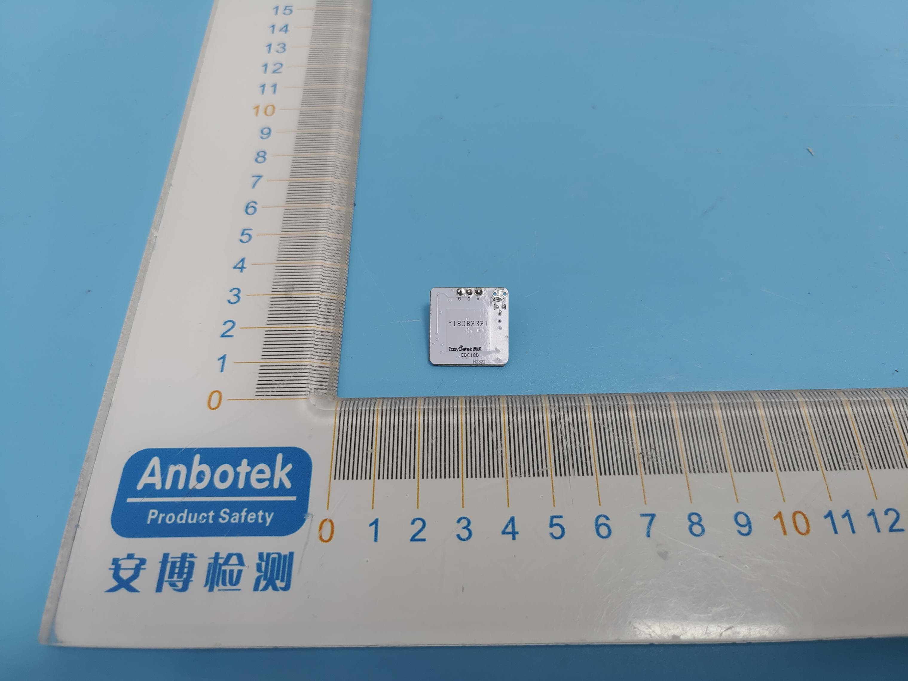
2ARDMEDC18D
Mar 12, 2024EDC18D
Equipment Class
DXX - Part 15 Low Power Communication Device Transmitter