2ARGT-NEXT1LBluetooth Earphones
MTI Corporation
Click to zoom
Application Details
- Equipment Class
- DSS - Part 15 Spread Spectrum Transmitter
- Date of Grant
- Nov 21, 2022
- Application Purpose
- Original Equipment
- Date of Application
- Nov 21, 2022
- Equipment Note
- Bluetooth Earphones
- Frequency Range
- 2402.00000000 - 2480.00000000
- Company
- MTI Corporation
- Country
- Japan
Documents & Files
Document Text
Text extracted from the exhibit documents filed with the FCC. Open a document above to read the original.
Users Manual
NEXT 1L manual Product Description Product Name: Bluetooth Earphones Model:NEXT 1L Brand Name:NUARL Bluetooth version: V5.2 Charging mode: 0.5A DC5V/USB power Battery : built-in rechargeable lithium battery Transmission Power: Class 2 Support profile: HFP A2DP AVRCP AVDTP GAP SDP Voice prompts Power on Power off Connected Low battery or please charge “ring bell” When the phone rings Pairing steps Please make sure the distance between the Bluetooth headset and the mobile phone is less than 1 meter when 1 st time pairing. Long press the MFB for 3 seconds, the Bluetooth headset will automatically enter the pairing status (the red and blue lights flash alternately) Turn on the mobile phone Bluetooth function Search for Bluetooth devices Select the pairing name for the headset L-BTE If pairing fails, please repeat the above operation or restart the phone The indicator light flashes blue after successful pairing Connect A phone with the Bluetooth headset successfully, then turn off the Bluetooth of the headset or disconnect the Bluetooth of the mobile phone, then turn on the Bluetooth mode of B phone and connect, and finally turn on A phone and connect the Bluetooth headset. Drag two function Operation Power on – Long press the MFB for 3s, the BLUE light flashes and you will hear “Power on” Power off – Long press the MFB for 4s, the RED light flashes and you will hear “Power off” Answering a call: When there is an incoming call on mobile phones, the BT earphones and the mobile phone will ring simultaneously. Press the answer key of the mobile phone to answer or click the headset MFB, the call will be connected. Or long press the MFB to reject the phone call. Hang up: press the hang up key of the mobile phones or single press MFB to hang up the phone call. Call reject – Reject by your phone or long press MFB for 3s Play music- After the mobile phone device is successfully connected, open the mobile phone music player for music playback. At this time, click the function key to pause. When the phone has an incoming call, the music will automatically stop and the incoming call ringtone will be connected. Song selection – long press + for 2 seconds for next song. Long press - for previous song. Volume adjustment – Press the “Volume +” or “Volume –” button to increase or decrease the volume Last number redial – when the headset is connecting to a phone and in standby mode, you can double MFB to redial the last called number Siri - long press for 2 seconds at standby mode to activate voice prompts Turn on to connect - When the headset is restarted, it will automatically search back to the previous phone for about 10-15 seconds. Function overview Next song/Volume + Multifunction button: Play/Pause/ Hang on/Hang off/Siri Previous song/volume - NOTE: This equipment has been tested and found to comply with the limits for a Class B digital device, pursuant to part 15 of the FCC Rules. These limits are designed to provide reasonable protection against harmful interference in a residential installation. This equipment generates uses and can radiate radio frequency energy and, if not installed and used in accordance with the instructions, may cause harmful interference to radio communications. However, there is no guarantee that interference will not occur in a particular installation. If this equipment does cause harmful interference to radio or television reception, which can be determined by turning the equipment off and on, the user is encouraged to try to correct the interference by one or more of the following measures: - Reorient or relocate the receiving antenna. - Increase the separation between the equipment and receiver. -Connect the equipment into an outlet on a circuit different from that to which the receiver is connected. -Consult the dealer or an experienced radio/TV technician for help Changes or modifications not expressly approved by the party responsible for compliance could void the user's authority to operate the equipment. Responsible Party: Company name: Address: Tel: E-mail FCC ID:2ARGT-NEXT1L
Cover Letter(s)
MTI Corporation Agent Authorization Company: MTI Corporation Address: 2-18-7 Keian Bldg. 4F Higashi Ikebukuro Toshima-Ku Tokyo 170-0013 Japan Product Name: Bluetooth Earphones Model Number(s): NEXT 1L Product Description: Bluetooth Earphones We authorize MiCOM Labs Inc., 575 Boulder Court, Pleasanton, California 94566, USA, to act on our behalf on all matters concerning the certification of above named equipment. We declare that MiCOM Labs Inc. is allowed to forward all information related to the approval and certification of equipment to the regulatory agencies as required and to discuss any issues concerning the approval application. Any and all acts carried out by MiCOM Labs on our behalf shall have the same effect as acts of our own. Signature: Date: 2022-10-31 Name: Keitetsu Cho Company: MTI Corporation
External Photos
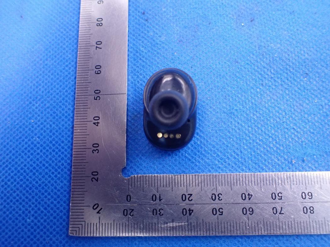
Report No.: AGC00427221001AP02 Page 1 of 4 EXTERNAL PHOTOS ALL VIEW OF EUT TOP VIEW OF EUT Report No.: AGC00427221001AP02 Page 2 of 4 BOTTOM VIEW OF EUT FRONT VIEW OF EUT Report No.: AGC00427221001AP02 Page 3 of 4 BACK VIEW OF EUT LEFT VIEW OF EUT Report No.: AGC00427221001AP02 Page 4 of 4 RIGHT VIEW OF EUT ****************************************End of Report****************************************
ID Label/Location Info
FCC ID Label Location The product does not have enough space to place the label, and FCC ID label is reflected in the user manual and package, as below:
Internal Photos
Report No.: AGC00427221001AP02 Page 1 of 5 INTERNAL PHOTOS OPEN VIEW OF EUT (FIGURE 1) OPEN VIEW OF EUT (FIGURE 2) BT Antenna BT Antenna Report No.: AGC00427221001AP02 Page 2 of 5 BATTERY VIEW OF EUT INTERNAL VIEW OF EUT (FIGURE 1) Report No.: AGC00427221001AP02 Page 3 of 5 INTERNAL VIEW OF EUT (FIGURE 2) INTERNAL VIEW OF EUT (FIGURE 3) Report No.: AGC00427221001AP02 Page 4 of 5 INTERNAL VIEW OF EUT (FIGURE 4) INTERNAL VIEW OF EUT (FIGURE 5) Report No.: AGC00427221001AP02 Page 5 of 5 INTERNAL VIEW OF EUT (FIGURE 6) INTERNAL VIEW OF EUT (FIGURE 7) ****************************************End of Report****************************************
RF Exposure Info
RF EXPOSURE EVALUATION 1. PRODUCT INFORMATION Product Description Bluetooth Earphones Model Name NEXT 1L FCC ID 2ARGT-NEXT1L 2. EVALUATION METHOD According to 447498 D01 General RF Exposure Guidance v06 The 1-g and 10-g SAR test exclusion thresholds for 100 MHz to 6 GHz at test separation distances ≤ 50 mm are determined by: [(max. power of channel, including tune-up tolerance, mW)/(min. test separation distance, mm)] ·[√f(GHz)] ≤ 3.0 for 1-g SAR and ≤ 7.5 for 10-g extremity SAR. Where f(GHz) is the RF channel transmit frequency in GHz Power and distance are rounded to the nearest mW and mm before calculation 3. CALCULATION Left: P t =9.623dBm=9.17mW The value of the Maximum output power P t is referred to the test report of the CFR47 §15.247. The result for RF exposure evaluation SAR=(9.17mW /5mm) .[√2.480GHz)]=2.88<3.0 for 1-g SAR and ≤ 7.5 for 10-g extremity SAR. Right: P t =9.394dBm=8.70mW The value of the Maximum output power P t is referred to the test report of the CFR47 §15.247. The result for RF exposure evaluation SAR=(8.70mW /5mm) .[√2.441GHz)]=2.71<3.0 for 1-g SAR and ≤ 7.5 for 10-g extremity SAR. 4. CONCLUSION The SAR evaluation is not required.
Test Report
Project: D86 Author: Mei Ting Huang File Name: D86_APP_A.doc Date: 2022-10-18 Revision: A CONFIDENTIAL Shenzhen OnePlusOne Wireless Communication Technology Co.,Ltd. Page 1 of 6 Shenzhen One Plus One Wireless Communication Technology Co., LTD APPROVAL SHEET 客户 Customer 项目名 Project D86 料号 Part NO. 规格 Specification BT Antennas APPROVAL OnePlusOne: RF Check ME Check QC Check Confirm By Customer: EE Check PM Check QC Check Confirm By Date: Revision: Updates and changes: Issued by: 承认鉴章后请寄回承认书一份 Please return to us one copy of “APPROVAL SHEET” with your approved signatures Pl Project: D86 Author: Mei Ting Huang File Name: D86_APP_A.doc Date: 2022-10-18 Revision: A CONFIDENTIAL Shenzhen OnePlusOne Wireless Communication Technology Co.,Ltd. Page 2 of 6 2022-06-13 A Initial sheet Mei Ting Huang Contents 1 ANTENNA DESCRIPTION ................................................................................1-3 IT SUMMARIZE WIFI ANTENNAS FOR PROJECT 24G-32T93-03. WIFI ANTENNA’S FREQUENCY BAND IS 2400-2500MHZ, ...................................................................1-3 1.1 Part number ..................................................................................... 1-3 2 ELECTRICAL PERFORMANCE ........................................................................2-3 2.1 Specification ..................................................................................... 2-3 2.1 Measurement Set-up ........................................................................ 2-4 2.1.1 VSWR and Return Loss ................................................................................................................... 2-4 2.1.2 Efficiency and Gain .......................................................................................................................... 2-4 3 REFERENCE MEASUREMENT DATA .............................................................3-4 3.1 Passive ............................................................................................... 3-4 3.2 Matching Circuit Description ......................................................... 3-5 4 MECHANICAL DESCRIPTION ..........................................................................4-5 4.1 Drawings ........................................................................................... 4-5 Project: D86 Author: Mei Ting Huang File Name: D86_APP_A.doc Date: 2022-10-18 Revision: A CONFIDENTIAL Shenzhen OnePlusOne Wireless Communication Technology Co.,Ltd. Page 3 of 6 1 Antenna description It summarize BTantennas for project D86. BT,antenna’s frequency band is 2400-2500MHz,. 1.1 Part number Part number of antenna:D86 Antenna pictures 2 Electrical Performance 2.1 Specification BT Frequency Range 2400MHz~2500MHz Return Loss <-5 Efficiency >25% Project: D86 Author: Mei Ting Huang File Name: D86_APP_A.doc Date: 2022-10-18 Revision: A CONFIDENTIAL Shenzhen OnePlusOne Wireless Communication Technology Co.,Ltd. Page 4 of 6 2.1 Measurement Set-up 2.1.1 VSWR and Return Loss VSWR measurements (S 11 ) were performed using an Agilent ENA series Network Analyzer and the previously described test fixture. Coaxial chokes were used to mitigate surface currents on the outside of the cabling. The testing was performed in free space. 2.1.2 Efficiency and Gain The gain of the antenna was measured in OPO’s 3D anechoic chamber in Shenzhen, China. The chamber is a ETS system capable of doing tests from 380MHz to 6GHz. Coaxial chokes on the feed cable were used to mitigate surface currents during passive tests. The measurement results are calibrated using dipole standards. For TRP and TIS the chamber uses a 8960 / MT8820C to establish the connection with the mobile device and read the power. 3 Reference measurement data 3.1 Passive Return Loss-L Project: D86 Author: Mei Ting Huang File Name: D86_APP_A.doc Date: 2022-10-18 Revision: A CONFIDENTIAL Shenzhen OnePlusOne Wireless Communication Technology Co.,Ltd. Page 5 of 6 Return Loss-R 3.2 Matching Circuit Description 4 Mechanical description 4.1 Drawings Project: D86 Author: Mei Ting Huang File Name: D86_APP_A.doc Date: 2022-10-18 Revision: A CONFIDENTIAL Shenzhen OnePlusOne Wireless Communication Technology Co.,Ltd. Page 6 of 6
Test Report
Page 1 of 72 FCC Test Report Report No.: AGC00427221001FE03 FCC ID : 2ARGT-NEXT1L APPLICATION PURPOSE : Original Equipment PRODUCT DESIGNATION : Bluetooth Earphones BRAND NAME : NUARL MODEL NAME : NEXT 1L APPLICANT : MTI Corporation DATE OF ISSUE : Oct. 26, 2022 STANDARD(S) : FCC Part 15.247 REPORT VERSION : V1.0 Attestation of Global Compliance (Shenzhen) Co., Ltd Report No.: AGC00427221001FE03 Page 2 of 72 REPORT REVISE RECORD Report Version Revise Time Issued Date Valid Version Notes V1.0 / Oct. 26, 2022 Valid Initial Release Report No.: AGC00427221001FE03 Page 3 of 72 TABLE OF CONTENTS 1. VERIFICATION OF CONFORMITY .................................................................................................................. 5 2. GENERAL INFORMATION .............................................................................................................................. 6 2.1. PRODUCT DESCRIPTION ........................................................................................................................ 6 2.2. TABLE OF CARRIER FREQUENCYS ....................................................................................................... 6 2.3. RECEIVER INPUT BANDWIDTH .............................................................................................................. 7 2.4. EXAMPLE OF A HOPPING SEQUENCY IN DATA MODE ......................................................................... 7 2.5. EQUALLY AVERAGE USE OF FREQUENCIES AND BEHAVIOUR ......................................................... 7 2.6. RELATED SUBMITTAL(S) / GRANT (S) .................................................................................................... 8 2.7. TEST METHODOLOGY ............................................................................................................................. 8 2.8. SPECIAL ACCESSORIES ......................................................................................................................... 8 2.9. EQUIPMENT MODIFICATIONS ................................................................................................................. 8 2.10. ANTENNA REQUIREMENT..................................................................................................................... 8 3. MEASUREMENT UNCERTAINTY ................................................................................................................... 9 4. DESCRIPTION OF TEST MODES ................................................................................................................. 10 5. SYSTEM TEST CONFIGURATION ................................................................................................................. 11 5.1. CONFIGURATION OF EUT SYSTEM ....................................................................................................... 11 5.2. EQUIPMENT USED IN TESTED SYSTEM ............................................................................................... 11 5.3. SUMMARY OF TEST RESULTS ............................................................................................................... 11 6. TEST FACILITY .............................................................................................................................................. 12 7. PEAK OUTPUT POWER ................................................................................................................................ 13 7.1. MEASUREMENT PROCEDURE ............................................................................................................. 13 7.2. TEST SET-UP (BLOCK DIAGRAM OF CONFIGURATION) .................................................................... 13 7.3. LIMITS AND MEASUREMENT RESULT .................................................................................................. 14 8. 20DB BANDWIDTH ........................................................................................................................................ 24 8.1. MEASUREMENT PROCEDURE ............................................................................................................. 24 8.2. TEST SET-UP (BLOCK DIAGRAM OF CONFIGURATION) .................................................................... 24 8.3. LIMITS AND MEASUREMENT RESULTS ............................................................................................... 25 9. CONDUCTED SPURIOUS EMISSION........................................................................................................... 30 9.1. MEASUREMENT PROCEDURE ............................................................................................................. 30 9.2. TEST SET-UP (BLOCK DIAGRAM OF CONFIGURATION) .................................................................... 30 Report No.: AGC00427221001FE03 Page 4 of 72 9.3. MEASUREMENT EQUIPMENT USED .................................................................................................... 30 9.4. LIMITS AND MEASUREMENT RESULT .................................................................................................. 30 10. RADIATED EMISSION ................................................................................................................................. 51 10.1. MEASUREMENT PROCEDURE ........................................................................................................... 51 10.2. TEST SETUP ......................................................................................................................................... 53 10.3. LIMITS AND MEASUREMENT RESULT ............................................................................................... 54 10.4. TEST RESULT........................................................................................................................................ 54 11. NUMBER OF HOPPING FREQUENCY ...................................................................................…
Text truncated - open the document above for the full version.
Test Report
Report No.: AGC00427221001FE03 Page 61 of 72 EUT Bluetooth Earphones Model Name NEXT 1L Temperature 23°C Relative Humidity 56% Pressure 985hPa Test Voltage Normal Voltage Test Mode Mode 4 Antenna Vertical Test Graph for Peak Measurement Test Graph for Average Measurement RESULT: PASS Report No.: AGC00427221001FE03 Page 62 of 72 EUT Bluetooth Earphones Model Name NEXT 1L Temperature 23°C Relative Humidity 56% Pressure 985hPa Test Voltage Normal Voltage Test Mode Mode 6 Antenna Horizontal Test Graph for Peak Measurement Test Graph for Average Measurement RESULT: PASS Report No.: AGC00427221001FE03 Page 63 of 72 EUT Bluetooth Earphones Model Name NEXT 1L Temperature 23°C Relative Humidity 56% Pressure 985hPa Test Voltage Normal Voltage Test Mode Mode 6 Antenna Vertical Test Graph for Peak Measurement Test Graph for Average Measurement RESULT: PASS Note: The factor had been edited in the “Input Correction” of the Spectrum Analyzer. The π /4-DQPSK modulation is the worst case and recorded in the report. Report No.: AGC00427221001FE03 Page 64 of 72 11. NUMBER OF HOPPING FREQUENCY 11.1. MEASUREMENT PROCEDURE The EUT shall have its hopping function enabled. Use the following spectrum analyzer settings: 1. Span: The frequency band of operation. Depending on the number of channels the device supports, it may be necessary to divide the frequency range of operation across multiple spans, to allow the individual channels to be clearly seen. 2. RBW: To identify clearly the individual channels, set the RBW to less than 30% of the channel spacing or the 20 dB bandwidth, whichever is smaller. 3. VBW ≥ RBW. Sweep: Auto. Detector function: Peak. Trace: Max hold. 4. Allow the trace to stabilize. 11.2. TEST SETUP (BLOCK DIAGRAM OF CONFIGURATION) Same as described in section 8.2 11.3. MEASUREMENT EQUIPMENT USED The same as described in section 6 11.4. LIMITS AND MEASUREMENT RESULT Test Data of Number of Hopping Frequency Test Mode Number of Hopping Frequency Limits Pass or Fail GFSK Hopping 79 >=15 Pass Test Graphs of Number of Hopping Frequency Test_Graph_BR_HOP_ANT1_NA_1Mbps_Number of Hopping Note: The GFSK modulation is the worst case and recorded in the report. Report No.: AGC00427221001FE03 Page 65 of 72 12. TIME OF OCCUPANCY (DWELL TIME) 12.1. MEASUREMENT PROCEDURE The EUT shall have its hopping function enabled. Use the following spectrum analyzer settings: 1. Span: Zero span, centered on a hopping channel. 2. RBW shall be≤channel spacing and where possible RBW should be set >> 1 / T, where T is the expected dwell time per channel. 3. Sweep: As necessary to capture the entire dwell time per hopping channel; where possible use a video trigger and trigger delay so that the transmitted signal starts a little to the right of the start of the plot. The trigger level might need slight adjustment to prevent triggering when the system hops on an adjacent channel; a second plot might be needed with a longer sweep time to show two successive hops on a channel. 4. Detector function: Peak. Trace: Max hold. 5. Use the marker-delta function to determine the transmit time per hop. 6. Repeat the measurement using a longer sweep time to determine the number of hops over the period specified in the requirements. The sweep time shall be equal to, or less than, the period specified in the requirements. Determine the number of hops over the sweep time and calculate the total number of hops in the period specified in the requirements, using the following equation: (Number of hops in the period specified in the requirements) = (number of hops on spectrum analyzer) × (period specified in the requirements / analyzer sweep time). 7. The average time of occupancy is calculated from the transmit time per hop multiplied by the number of hops in the period specified in the requirements. 12.2. TEST SETUP (BLOCK DIAGRAM OF CONFIGURATION) Same as described in section 8.2 12.3. MEASUREMENT EQUIPMENT USED The same as described in section 6 12.4. LIMITS AND MEASUREMENT RESULT Test Data of Dwell Time Channel Time of Pulse for DH5 (ms) Number of hops in the period specified in the requirements Sweep Time (ms) Limit (ms) Pass or Fail 2402 2.877 27.0*4 310.716 400 Pass 2441 2.877 27.0*4 310.716 400 Pass 2480 2.877 27.0*4 310.716 400 Pass Note: The GFSK modulation is the worst case and recorded in the report. Report No.: AGC00427221001FE03 Page 66 of 72 Test Graphs of Dwell Time Test_Graph_BR_HOP_ANT1_NA_1Mbps_2402_Number of Busrt Test_Graph_BR_HOP_ANT1_NA_1Mbps_2402_Time per Burst Report No.: AGC00427221001FE03 Page 67 of 72 Test_Graph_BR_HOP_ANT1_NA_1Mbps_2441_Number of Busrt Test_Graph_BR_HOP_ANT1_NA_1Mbps_2441_Time per Burst Report No.: AGC00427221001FE03 Page 68 of 72 Test_Graph_BR_HOP_ANT1_NA_1Mbps_2480_Number of Busrt Test_Graph_BR_HOP_ANT1_NA_1Mbps_2480_Time per Burst Report No.: AGC00427221001FE03 Page 69 of 72 13. FREQUENCY SEPARATION 13.1. MEASUREMENT PROCEDURE The EUT shall have its hopping function enabled. Use the following spectrum analyzer settings: 1. Span: Wide enough to capture the peaks of two adjacent channels. 2. RBW: Start with the RBW set to approximately 30% of the channel spacing; adjust as necessary to best identify the center of each individual channel. 3. Video (or average) bandwidth (VBW) ≥ RBW. 4. Sweep: Auto. e) Detector function: Peak. f) Trace: Max hold. g) Allow the trace to stabilize. Use the marker-delta function to determine the separation between the peaks of the adjacent channels. 13.2. TEST SETUP (BLOCK DIAGRAM OF CONFIGURATION) Same as described in section 6.2 13.3. MEASUREMENT EQUIPMENT USED The same as described in section 6.3 13.4. LIMITS AND MEASUREMENT RESULT Test Data of Frequency Separation Test Mode Channel Separation (MHz) Limits Pass or Fail GFSK Hopping 0.961 >= 2/3 -20dB BW Pass Test Graphs of Number of Hopping Frequency Test_Graph_BR_HOP_ANT1_NA_1Mbps_Hopping Separation Note: The GFSK modulation is the worst case and recorded in the report. Report No.: AGC00427221001FE03 Page 70 of 72 14.…
Text truncated - open the document above for the full version.
Test Setup Photos
Report No.: AGC00427221001AP01 Page 1 of 2 TEST SETUP PHOTOS RADIATED EMISSION TEST SETUP BELOW 1GHz RADIATED EMISSION TEST SETUP ABOVE 1GHz Report No.: AGC00427221001AP01 Page 2 of 2 RF CONDUCTED TEST SETUP (Left) RF CONDUCTED TEST SETUP (Right) ****************************************End of Report*************************************
Contact Information
Applicant
Keitetsu Cho(Manager)
Technical Contact
Test Firm
Attestation of Global Compliance (Shenzhen) Co., LDoris Li
[email protected]+86-755-25234088
Technical Specifications
| # | Rule Parts | Frequency Range | Power Output |
|---|---|---|---|
| 1 | 15C | 2.40 GHz - 2.48 GHz | 9.20 mW |
Other Applications from MTI Corporation
2ARGT-N10PLUS
Mar 23, 2021Bluetooth ANC TRULY WIRELESS STEREO EARBUDS
Equipment Class
DTS - Digital Transmission System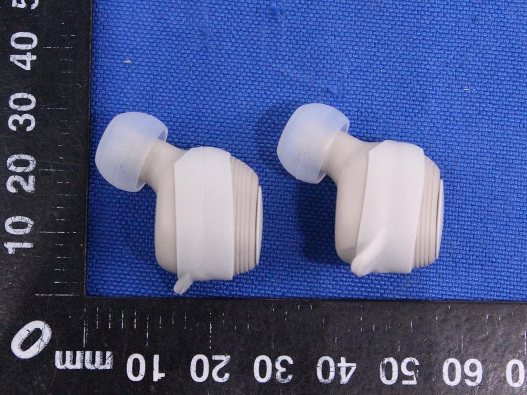
2ARGT-N6SPORTS
Oct 22, 2020Bluetooth Headset
Equipment Class
DSS - Part 15 Spread Spectrum Transmitter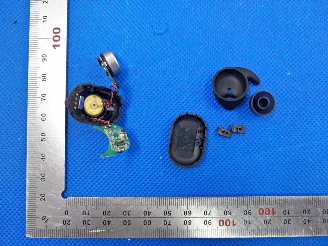
2ARGT-N10PRO
Aug 05, 2020Bluetooth ANC Truly Wireless Stereo Earbuds
Equipment Class
DTS - Digital Transmission System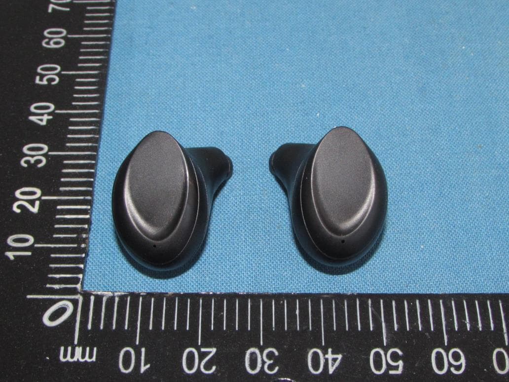
2ARGT-NUARLN6MINI
Jul 12, 2020Bluetooth Earphones
Equipment Class
DSS - Part 15 Spread Spectrum Transmitter