FCCID.CO- FCC ID Database
HomeCompaniesEquipment ClassesSearch

© 2026 FCC ID Database. All rights reserved.

AboutContactData sourced from FCC public records
  1. Home/
  2. CoreKinect/
  3. 2ARKMNATLRA1

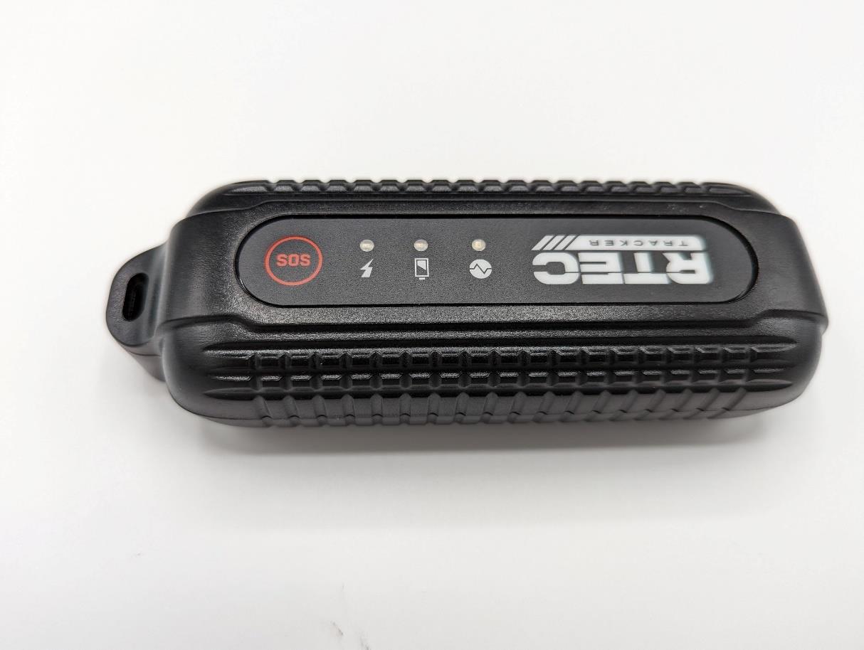
2ARKMNATLRA1LoRa Vehicle Asset Tracker

CoreKinect
LoRa Vehicle Asset Tracker - FCC ID 2ARKMNATLRA1 - CoreKinect
Click to zoom

Application Details

Equipment Class
DSS - Part 15 Spread Spectrum Transmitter
Date of Grant
Jul 12, 2020
Application Purpose
Original Equipment
Date of Application
Jul 12, 2020
Equipment Note
LoRa Vehicle Asset Tracker
Frequency Range
903.00000000 - 914.20000000
Company
CoreKinect
Country
United States

Documents & Files

Select a file to view

Users Manual

Cover Letter(s)

↗
↗

External Photos

↗

ID Label/Location Info

↗

Internal Photos

↗

RF Exposure Info

↗

Test Report

↗

Test Setup Photos

↗

Document Text

Text extracted from the exhibit documents filed with the FCC. Open a document above to read the original.

Cover Letter(s)

23/03/2020 TUV SUD BABT TCB/FCB Octagon House, Segensworth Road, Fareham, Hampshire, PO15 5RL Dear Sir or Madam, We, CoreKinect, hereby authorize H.B. Compliance Solutions, located at5005 S. Ash Avenue, Suite # A- 10Tempe, AZ-85282,to act as our agent in all matters relating to applications for equipment authorization, including the signing of all documents relating to these matters. This authorization expires on 01/03/2021 Sincerely, Company Officer: Assar Badri, CEO Telephone Number: +1-602-684-5484 Email: [email protected]

Cover Letter(s)

23/03/2020 TUV SUD BABT TCB/FCB Octagon House, Segensworth Road, Fareham, Hampshire, PO15 5RL Confidentiality Request FCC ID: 2ARKMNATLRA1 Pursuant to Sections 0.457(d)(1)(ii) and 0.459 of the Commission’s Rules, CoreKinect hereby requests permanent confidential treatment of information accompanying this application as outlined below: Schematics Bill of Materials/Parts List Block Diagrams Theory of Operation CoreKinect also hereby requests short-term confidential treatment of information accompanying this application as outlined below for a period of 180 days: Internal Photos External Photos User Manual Test Set-up Photographs The above materials contain trade secrets and proprietary information not customarily released to the public. The public disclosure of these matters might be harmful to the Applicant and provide unjustified benefits to its competitors. The Applicant understands that pursuant to Rule 0.457(d)(1)(ii), disclosure of this Application and all accompanying materials will not be made before the date of the Grant for this Application. Yours sincerely, Company Officer: Assar Badri, CEO Telephone Number: +1-602-684-5484 Email: [email protected]

External Photos

Exhibit 3: External Photos

ID Label/Location Info

CoreKinect Confidential- Project NUR- Label Spec V 3 5 NATLRA1- Laser Etch Label Artwork Model: NATLRA1 HVIN: B0 Serial: NATL1XXXXXXX FCC ID: 2ARKMNATLRA1 IC: 24436-NATLRA1 Made in USA

Internal Photos

Exhibit 9: Internal Photos

RF Exposure Info

Certificates and reports shall not be reproduced except in full, without the written permission of H.B Compliance Solutions, LLC. Maximum Permissible Exposure Statement For the CoreKinect LoRa Vehicle Asset Tracker Model # NATLRA1 March 25, 2020 Prepared for: CoreKinect 2800 S. Rural Road, Suite 103 Tempe, Arizona 85282 Prepared By: H.B. Compliance Solutions 5005 S. Ash Avenue, Suite # A-10 Tempe, Arizona 85282 Reviewed By: Hoosamuddin Bandukwala Cert # ATL-0062-E HBCS MPE Report # EMC_20006 Page 2 of 2 Prediction of MPE limit at a given distance Equation from page 18 of OET Bulletin 65, Edition 97-01 S = PG/4πR2 Where, S = power density (mW/cm2) P = output power at the antenna terminal (mW) G = gain of transmit antenna (numeric) R = distance from transmitting antenna (cm) Maximum peak output power at antenna input terminal = 18.04 (dBm) Maximum peak output power at antenna input terminal = 63.68 (mW) Antenna gain (typical) = 0(dBi) Maximum antenna gain = 1.0 (numeric) Prediction distance = 20 (cm) Prediction frequency = 914.2 (MHz) MPE limit for uncontrolled exposure at prediction frequency = 0.609 (mW/cm^2) Power density at prediction frequency = 0.01266 (mW/cm^2) To solve for the minimum mounting distance required; R = √ (PG/4πS) R = √ (63.68 x 1.0 / 4π x 0.01266) = 20 cm (Based on continuous transmission) END OF TEST REPORT

Test Report

Certificates and reports shall not be reproduced except in full, without the written permission of H.B Compliance Solutions, LLC. Intentional Radiator Test Report For the CoreKinect LoRA Vehicle Asset Tracker Model # NATLRA1 Tested under The FCC Rules contained in Title 47 of the CFR, Part 15.247 for Hybrid System Prepared for: CoreKinect 2800 S. Rural Road, Suite 103 Tempe, Arizona 85282 Prepared By: H.B. Compliance Solutions 5005 S. Ash Avenue, Suite # A-10 Tempe, Arizona 85282 Reviewed By: Hoosamuddin Bandukwala Cert # ATL-0062-E Engineering Statement: The measurements shown in this report were made in accordance with the procedure indicated, and the emissions from this equipment were found to be within the limits applicable. I assume full responsibility for the accuracy and completeness of these measurements, and for the qualifications of all persons taking them. It is further stated that upon the basis of the measurement made, the equipment tested is capable of operation in accordance with the requirements of Part 15 of the FCC Rules under normal use and maintenance. All results contained herein relate only to the sample tested. HBCS Report # RF_20006 Rev1 Page 2 of 51 Report Status Sheet Revision # Report Date Reason for Revision Ø March 18, 2020 Initial Issue 1 July 6, 2020 TCB Comments HBCS Report # RF_20006 Rev1 Page 3 of 51 Table of Contents EXECUTIVE SUMMARY ............................................................................................ 5 1. Testing Summary ........................................................................................ 5 EQUIPMENT CONFIGURATION ................................................................................ 6 1. Overview .................................................................................................... 6 2. Test Facility ................................................................................................. 7 3. Description of Test Sample ......................................................................... 8 4. Equipment Configuration ........................................................................... 8 5. Support Equipment .................................................................................... 8 6. Ports and Cabling Information .................................................................... 8 7. Method of Monitoring EUT Operation ........................................................ 8 8. Mode of Operation ..................................................................................... 9 9. Modifications ............................................................................................. 9 10. Disposition of EUT ...................................................................................... 9 Criteria for Un-Intentional Radiators .................................................................... 10 1. Radiated Emissions ................................................................................... 10 Emissions Tests Calculations ...................................................................... 11 Criteria for Intentional Radiators .......................................................................... 14 1. Occupied Bandwidth ................................................................................ 14 2. RF Power Output ...................................................................................... 19 3. Conducted Spurious Emissions ................................................................. 23 4. Radiated Spurious Emissions and Restricted Band ................................... 31 6. Emissions At Band Edges .......................................................................... 35 7. Power Spectral Density ............................................................................. 40 8. Time of Occupancy (Dwell Time) .............................................................. 44 9. Number of Hopping Frequencies .............................................................. 47 10. Carrier Frequency Separation ................................................................... 48 HBCS Report # RF_20006 Rev1 Page 4 of 51 11. Test Equipment ........................................................................................... 50 12. Measurement Uncertainty .......................................................................... 51 HBCS Report # RF_20006 Rev1 Page 5 of 51 EXECUTIVE SUMMARY 1. Testing Summary These tests were conducted on a sample of the equipment for the purpose of demonstrating compliance with Part 15.247. All tests were conducted using measurement procedure from ANSI C63.10-2013, FCC Guidance document 558074 D01 v05r02 April 02, 2019 as appropriate. Test Name Test Method/Standard Result Comments Unintentional Radiated Emissions 15.109 Pass A/C Powerline Conducted Emissions 15.207 N/A Battery Powered Device Occupied Bandwidth 15.247(a)(2) Pass Peak Output Power 15.247(b) Pass Conducted Spurious Emissions 15.247(d) Pass Radiated Spurious Emissions & Restricted Band 15.247(d), 15.209(a), 15.205 Pass Emissions at Band Edges 15.247(d), 15.209(a), 15.205 Pass Power Spectral Density 15.247(e) Pass Time of Occupancy (Dwell Time) 15.247(a) Pass Number of Hopping Channels 15.247(a) Pass Carrier Frequency Separation 15.247(a) Pass HBCS Report # RF_20006 Rev1 Page 6 of 51 EQUIPMENT CONFIGURATION 1. Overview H.B Compliance Solutions was contracted by CoreKinect to perform testing on the LoRa Vehicle Asset Tracker under the quotation number Q20011008. This document describes the test setups, test methods, required test equipment, and the test limit criteria used to perform compliance testing of the CoreKinect, LoRa Vehicle Asset Tracker. The tests were based on FCC Part 15 Rules. The tests described in this document were formal tests as described with the objective of the testing was to evaluate compliance of the Equipment Under Test (EUT) to the requirements of the aforementioned specific…

Text truncated - open the document above for the full version.

Test Setup Photos

1 | P a g e Test Setup Photos CoreKinect – Project 20006 Test Setup Photo # 1 Test Setup Photo # 2 2 | P a g e Test Setup Photo # 3

Contact Information

Applicant

Assar Badri
[email protected]6023213250Fax: 6023213250

Test Firm

H.B. Compliance SolutionsHoosamuddin Bandukwala
[email protected]480-684-2969

Technical Specifications

#Rule PartsFrequency RangePower Output
215C903 MHz - 914.2 MHz63.00 mW
Confidentiality
Long Term
Grant Notes
Power listed is conducted. The device and its antenna(s) must be installed to provide a separation distance of at least 20 cm from all persons. Installers and end-users must be provided with operating conditions for satisfying RF exposure compliance.

Other Applications from CoreKinect

JumpTrack - FCC ID 2ARKMCATLRA1 - CoreKinect
2ARKMCATLRA1

JumpTrack

Nov 09, 2022

Equipment Class

DSS - Part 15 Spread Spectrum Transmitter