2ARXU-MG101A-EDGEWireless Charging Case
Salom Electric (Xiamen) Co., Ltd.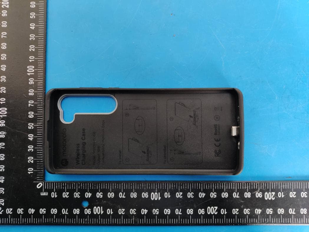
Click to zoom
Application Details
- Equipment Class
- JAV - Other Non-Digital SDoC Devices
- Date of Grant
- Jan 21, 2021
- Application Purpose
- Original Equipment
- Date of Application
- Jan 21, 2021
- Equipment Note
- Wireless Charging Case
- Country
- China
Documents & Files
Document Text
Text extracted from the exhibit documents filed with the FCC. Open a document above to read the original.
Users Manual
Wireless Charging Case User Guide (EDGE-WC-BK) es (pp.04- 05) de (pp. 1 0- 1 1 ) f r (pp.06-07) i t (pp. 1 2 - 1 3) en (pp.0 1 -03) p t (pp.08-09) Features: 1. Built in 10W Qi compatible receiver, 5V/1A, 9V/1.1A. 2. Wired USB-C input accepts 5V/3A, 9V/2A, QC3.0 & USB-PD 18W TurboPower pass through wired charging. Installation: 1. Attach your Motorola Edge USB-C charge port to the USB-C connector in the wireless charging case. 2. Align the bottom of the phone with the bottom of the case and push in. 3. Push the rest of the phone into the case. For wireless charging: Using a Qi wireless charging pad 1. Align the Motorola M-logo with the center of a wireless charging pad. 2. Place the back of the case onto a Qi wireless charging pad. 3. Ensure the wireless charging pad is charging. 4. Your device will begin to charge. Note: Wireless charging pad and USB-C cable are sold separately. For direct charging: Connect your charger and USB-C cable to the USB-C port at the bottom of the phone case. Note: Wall charger and USB-C cable are sold separately. Uninstallation: 1. Keep the bottom of the phone and case connected, slightly release the top of the Motorola edge phone for just enough to get out of the frame of the case top. 2. Keep the alignment of the bottom of the phone with the bottom of the case and pull the phone up from the case to disengage the USB-C charge port from the USB-C connector of case. FCC Notice to User This equipment has been tested and found to comply with the limits for a Class B digital device, pursuant to part 15 of the FCC Rules. See 47 CFR Sec. 15.105(b). These limits are designed to provide reasonable protection against harmful interference in a residential installation. This equipment generates, uses and can radiate radio frequency energy and, if not installed and used in accordance with the instructions, may cause harmful interference to radio communications. However, there is no guarantee that interference will not occur in a particular installation. If this equipment does cause harmful interference to radio or television reception, which can be determined by turning the equipment o and on, the user is encouraged to try to correct the interference by one or more of the following measures: • Reorient or relocate the receiving antenna. • Increase the separation between the equipment and the receiver. • Connect the equipment to an outlet on a circuit different from that to which the receiver is connected. • Consult the dealer or an experienced radio/TV technician for help. This device complies with Part 15 of the FCC rules. Operation is subject English 01 Features: 1. Built in 10W Qi compatible receiver, 5V/1A, 9V/1.1A. 2. Wired USB-C input accepts 5V/3A, 9V/2A, QC3.0 & USB-PD 18W TurboPower pass through wired charging. Installation: 1. Attach your Motorola Edge USB-C charge port to the USB-C connector in the wireless charging case. 2. Align the bottom of the phone with the bottom of the case and push in. 3. Push the rest of the phone into the case. For wireless charging: Using a Qi wireless charging pad 1. Align the Motorola M-logo with the center of a wireless charging pad. 2. Place the back of the case onto a Qi wireless charging pad. 3. Ensure the wireless charging pad is charging. 4. Your device will begin to charge. Note: Wireless charging pad and USB-C cable are sold separately. For direct charging: Connect your charger and USB-C cable to the USB-C port at the bottom of the phone case. Note: Wall charger and USB-C cable are sold separately. Uninstallation: 1. Keep the bottom of the phone and case connected, slightly release the top of the Motorola edge phone for just enough to get out of the frame of the case top. 2. Keep the alignment of the bottom of the phone with the bottom of the case and pull the phone up from the case to disengage the USB-C charge port from the USB-C connector of case. FCC Notice to User This equipment has been tested and found to comply with the limits for a Class B digital device, pursuant to part 15 of the FCC Rules. See 47 CFR Sec. 15.105(b). These limits are designed to provide reasonable protection against harmful interference in a residential installation. This equipment generates, uses and can radiate radio frequency energy and, if not installed and used in accordance with the instructions, may cause harmful interference to radio communications. However, there is no guarantee that interference will not occur in a particular installation. If this equipment does cause harmful interference to radio or television reception, which can be determined by turning the equipment o and on, the user is encouraged to try to correct the interference by one or more of the following measures: • Reorient or relocate the receiving antenna. • Increase the separation between the equipment and the receiver. • Connect the equipment to an outlet on a circuit different from that to which the receiver is connected. • Consult the dealer or an experienced radio/TV technician for help. This device complies with Part 15 of the FCC rules. Operation is subject 02 to the following two conditions: (1) this device may not cause harmful interference, and (2) this device must accept any interference received, including interference that may cause undesired operation. Industry Canada Notice to User, RSS-Gen Statement This device contains licence-exempt transmitter(s)/receiver(s) that comply with Innovation, Science and Economic Development Canada’s licenceexempt RSS(s). Operation is subject to the following two conditions: (1) This device may not cause interference. (2) This device must accept any interference, including interference that may cause undesired operation of the device. This device complies with ICES-003 requirements for Class B ITE (Information Technology Equipment). CAN ICES-3 (B)/NMB-3(B) Recycling of Waste Electrical and Electronic Equipment (WEEE) This symbol on the product or on its packaging indicates that this product must not be disposed of with y…
Text truncated - open the document above for the full version.
Cover Letter(s)
Salom Electric (Xiamen) Co., Ltd. Agent Authorization Company: Salom Electric (Xiamen) Co., Ltd. Address: 31 Building, Huli Industrial District, Xiamen, Fujian361006, P.R. China Product Name: Wireless Charging Case Model Number(s): MG101A-EDGE, MG101A, MG101A-001, MG101A-002, MG101A- 003, MG101A-004, MG101A-005, MG101A-006, MG101A-007, MG101A-008, MG101A-009, MG101A-010, MG101A-011, MG101A-012, MG101A-013, MG101A-014, MG101A-015, MG101A-016, MG101A-017, MG101A-018, MG101A-019, MG101A-020 Product Description: Wireless Charger Receiver We authorize MiCOM Labs Inc., 575 Boulder Court, Pleasanton, California 94566, USA, to act on our behalf on all matters concerning the certification of above named equipment. We declare that MiCOM Labs Inc. is allowed to forward all information related to the approval and certification of equipment to the regulatory agencies as required and to discuss any issues concerning the approval application. Any and all acts carried out by MiCOM Labs on our behalf shall have the same effect as acts of our own. Signature: Date: 2021-1-20 Name: Wu xiaojuan Title: Engineer Company: 31 Building, Huli Industrial District, Xiamen, Fujian361006, P.R. China
Cover Letter(s)
Salom Electric (Xiamen) Co., Ltd. Office of Engineering Technology Federal Communications Commission 7435 Oakland Mills Road Columbia, MD 21046 Date: 2021-1-20 Subject; Request for Long Term Confidentiality FCC ID: 2ARXU-MG101A-EDGE To Whom It May Concern, Pursuant to the provisions of the Commission’s rules Title 47 Sections §0.457 and §0.459, we are requesting the Commission to withhold the following attachment(s) as confidential documents from public disclosure indefinitely. These documents contain detailed system and equipment descriptions and are considered as proprietary information in operation of the equipment. The public disclosure of these documents might be harmful to our company and would give competitors an unfair advantage in the market. Schematic Diagram Block Diagram Operational Description It is our understanding that all measurement test reports, FCC ID label format and correspondence during the certification review process cannot be granted as confidential documents and this information will be available for public review once the grant of equipment authorization is issued. Sincerely, Signature: Name: Wu xiaojuan Title: Engineer
External Photos
FCC ID: 2ARXU-MG101A-EDGE
ID Label/Location Info
10mm 20mm Label Location FCC ID: 2ARXU-MG101A-EDGE Salom Electric (Xiamen) Co., Ltd. Model name: Wireless Charging Case Model No.: MG101A-EDGE This device complies with Part 15 of the FCC Rules. Operation is subject to the following two conditions: (1) this device may not cause harmful interference, and (2) this device must accept any interference received, including interference that may cause undesired operation.
Internal Photos
FCC ID: 2ARXU-MG101A-EDGE ANT
Test Report
FCC TEST REPORT FCC ID: 2ARXU-MG101A-EDGE On Behalf of Salom Electric (Xiamen) Co., Ltd. Wireless Charging Case Model No.: MG101A-EDGE, MG101A, MG101A-001, MG101A-002, MG101A-003, MG101A-004, MG101A-005, MG101A-006, MG101A-007, MG101A-008, MG101A-009, MG101A-010, MG101A-011, MG101A-012, MG101A-013, MG101A-014, MG101A-015, MG101A-016, MG101A-017, MG101A-018, MG101A-019, MG101A-020 Prepared for : Salom Electric (Xiamen) Co., Ltd. Address : 31 Building, Huli Industrial District, Xiamen, Fujian361006, P.R. China Prepared By : Shenzhen Alpha Product Testing Co., Ltd. Address : Building i, No.2, Lixin Road, Fuyong Street, Bao'an District, 518103, Shenzhen, Guangdong, China Report Number : A2008291-C01-R01 Date of Receipt : November 24, 2020 Date of Test : November 24, 2020–December 2, 2020 Date of Report : December 29, 2020 Version Number : V0 Page 2 of 30 Report No.: A2008291-C01-R01 TABLE OF CONTENTS Description Page 1. General Information ........................................................................................................... 5 1.1. Description of Device (EUT) ...................................................................................... 5 1.2. Accessories of Device (EUT) ..................................................................................... 5 1.3. Tested Supporting System Details. ............................................................................. 6 1.4. Block Diagram of connection between EUT and simulators ...................................... 6 2. Summary of Standards and Results .................................................................................. 7 2.1. Description of Standards and Results ......................................................................... 7 2.2. Test Mode Description ................................................................................................ 8 2.3. Test Equipment List .................................................................................................... 9 2.4. Test Facility .............................................................................................................. 10 2.5. Measurement Uncertainty ......................................................................................... 10 3. Power Line Conducted Emission Test ............................................................................. 11 3.1. Test Limits ................................................................................................................ 11 3.2. Block Diagram of Test Setup .................................................................................... 11 3.3. Configuration of EUT on Test .................................................................................. 12 3.4. Operating Condition of EUT .................................................................................... 12 3.5. Test Procedure .......................................................................................................... 12 3.6. Test Results ............................................................................................................... 13 4. Radiated Emission Test ..................................................................................................... 16 4.1. Test Limit .................................................................................................................. 16 4.2. Block Diagram of Test Setup .................................................................................... 17 4.3. Configuration of EUT on Test .................................................................................. 18 4.4. Operating Condition of EUT .................................................................................... 18 4.5. Test Procedure .......................................................................................................... 18 4.6. Test Results ............................................................................................................... 19 5. Photograph ......................................................................................................................... 23 5.1. Photo of Radiated Emission Test (In Semi Anechoic Chamber) .............................. 23 5.2. Photo of Power Line Conducted ............................................................................... 24 6. Photos of the EUT .............................................................................................................. 25 Page 3 of 30 Report No.: A2008291-C01-R01 TEST REPORT DECLARATION Applicant : Salom Electric (Xiamen) Co., Ltd. Address : 31 Building, Huli Industrial District, Xiamen, Fujian361006, P.R. China Manufacturer : Shenzhen Kangchengtai Industrial Co., Ltd. Address : 1-5F, the 1st building, No.128 Dayang Road, Dayang development zone, Fuyong street, Bao’an District, Shenzhen EUT Description : Wireless Charging Case (A) Model No. : MG101A-EDGE, MG101A, MG101A-001, MG101A-002, MG101A-003, MG101A-004, MG101A-005, MG101A-006, MG101A-007, MG101A-008, MG101A-009, MG101A-010, MG101A-011, MG101A-012, MG101A-013, MG101A-014, MG101A-015, MG101A-016, MG101A-017, MG101A-018, MG101A-019, MG101A-020 (B) Trademark : MOTOROLA Measurement Standard Used: FCC Rules and Regulations Part 15 Subpart B Class B, ANSI C63.4:2014 The device described above is tested by Shenzhen Alpha Product Testing Co., Ltd. to determine the maximum emission levels emanating from the device and the severe levels of the device can endure and its performance criterion. The test results are contained in this test report and Shenzhen Alpha Product Testing Co., Ltd. is assumed full responsibility for the accuracy and completeness of test. Also, this report shows that the EUT is technically compliant with the FCC Part 15 requirements. This report applies to above tested sample only. This report shall not be reproduced in parts without written approval of Shenzhen Alpha Product Testing Co., Ltd. Tested b…
Text truncated - open the document above for the full version.
Test Setup Photos
FCC ID: 2ARXU-MG101A-EDGE Photos of Radiated emission Photos of Conducted Emission test
Contact Information
Applicant
Guoxin Huang(Manager of Product Support Department)
Technical Contact
Test Firm
Shenzhen Alpha Product Testing Co., LTD.Simple Guan
[email protected]+86 755 29766001-810
Technical Specifications
| # | Rule Parts | Frequency Range | Power Output |
|---|---|---|---|
| 1 | 15B | - | - |
Other Applications from Salom Electric (Xiamen) Co., Ltd.
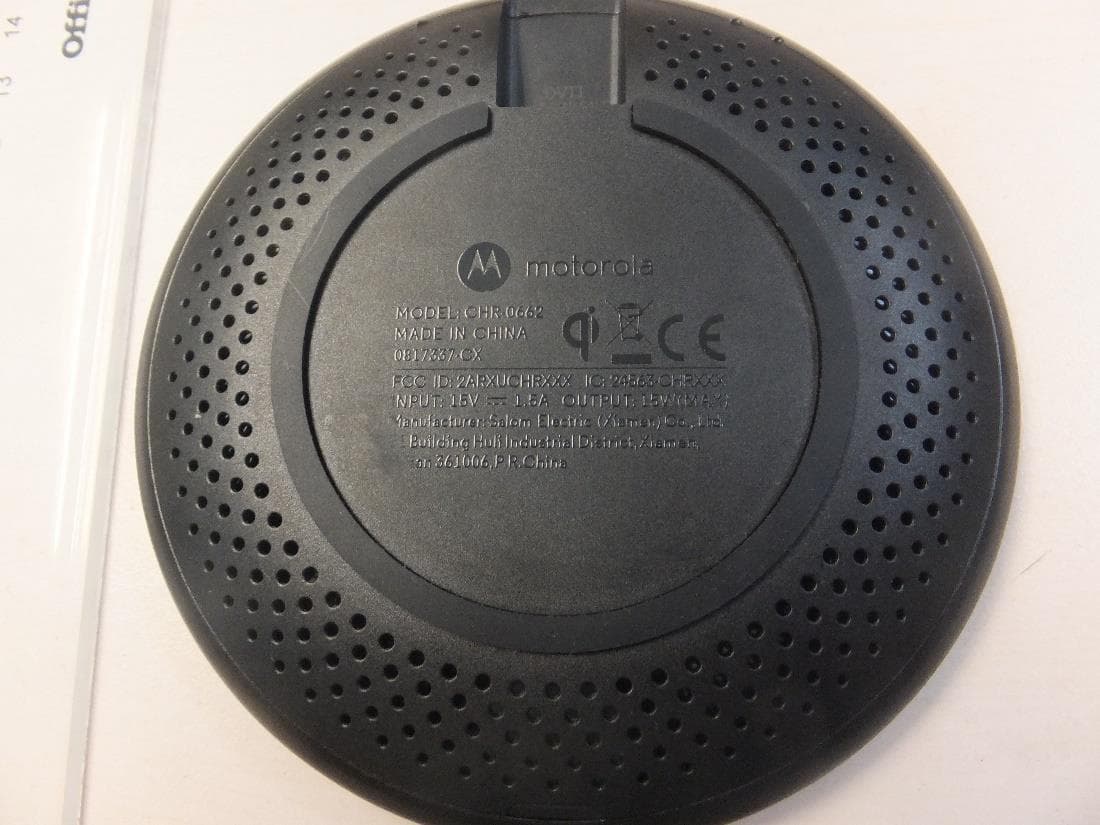
2ARXUCHR0662
Aug 16, 2020Wireless Charger
Equipment Class
DCD - Part 15 Low Power Transmitter Below 1705 kHz