FCCID.CO- FCC ID Database
HomeCompaniesEquipment ClassesSearch

© 2026 FCC ID Database. All rights reserved.

AboutContactData sourced from FCC public records
  1. Home/
  2. Emporia Corp/
  3. 2AS6P-EMCTV2

2AS6P-EMCTV2Smart Home Energy Monitor

Emporia Corp
Smart Home Energy Monitor - FCC ID 2AS6P-EMCTV2 - Emporia Corp
Click to zoom

Application Details

Equipment Class
DTS - Digital Transmission System
Date of Grant
Sep 26, 2020
Application Purpose
Original Equipment
Date of Application
Sep 26, 2020
Equipment Note
Smart Home Energy Monitor
Frequency Range
2412.00000000 - 2462.00000000
Company
Emporia Corp
Country
United States

Documents & Files

Select a file to view
Users Manual

↗

Cover Letter(s)

↗
↗
↗

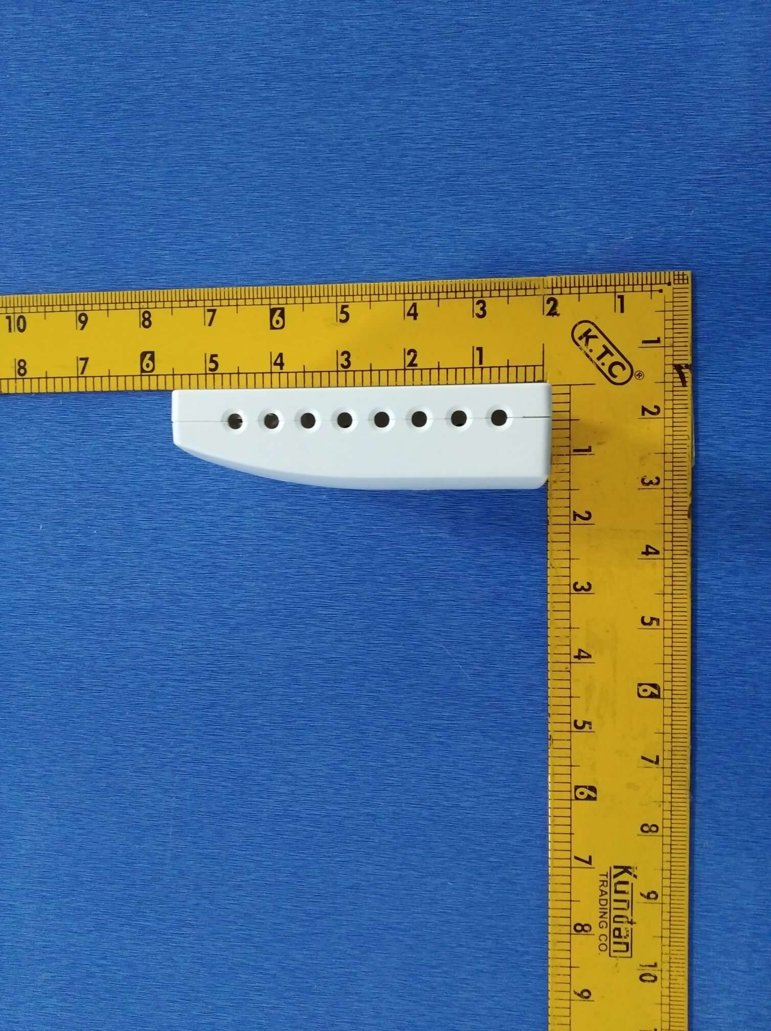
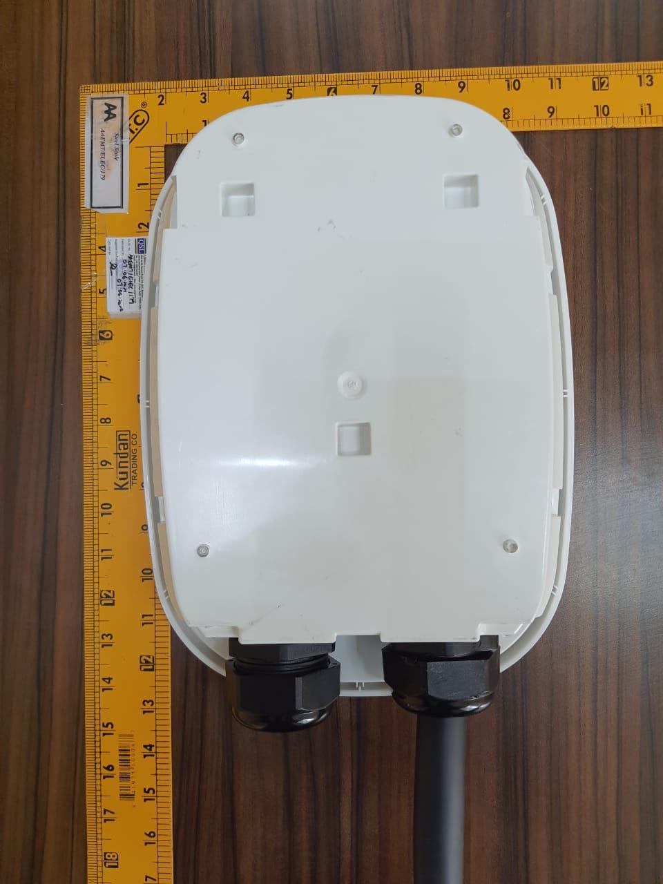
External Photos

↗

ID Label/Location Info

↗

Internal Photos

↗

RF Exposure Info

↗

Test Report

↗
↗

Test Setup Photos

↗

Document Text

Text extracted from the exhibit documents filed with the FCC. Open a document above to read the original.

Users Manual

Installation Guide WARNING! The Emporia Vue requires installing sensors inside your home’s electrical panel and working around dangerous voltage that could lead to injury or death. Emporia recommends that installation be performed by a licensed electrician or other qualified professional in accordance with the regional electrical code where it is being installed. Improper installation or use of the equipment can be dangerous or even fatal. In no event shall Emporia be liable to you or any third party for any damages, either direct or indirect, arising from or related to any personal injury as a result of your failure to follow the safety information and instructions in this Installation Guide. Safety information ◆ Personal protective gear should be worn when installing the Emporia Vue. ◆ Do not use the Emporia Vue in any manner other than specified in this installation guide. ◆ Do not attempt to open, disassemble, or repair any of the components of the Emporia Vue. ◆ If you believe any of the Emporia Vue components may have been damaged, do not attempt to use them. ◆ Do not install the Emporia Vue in environments with explosive gas or vapors; nor in damp or wet environments; nor in direct sunlight; nor where temperatures are consistently below -40° F (-40° C) or above 122° F (50° C). Need help? emporiaenergy.com/support [email protected] 1-844-EMPORIA (367-6742) Before you get started The Emporia Vue is installed in your home’s electrical panel. You’ll turn off the main breaker, which will shut off all of the power in your home. However, the service mains will remain dangerously energized. The following items may help with safe installation. It’s also helpful to perform the installation with a friend. Phillips and flathead screwdrivers Protective gloves Protective eyewear Alternative light source Need help? emporiaenergy.com/support [email protected] 1-844-EMPORIA (367-6742) What’s in the box Your new Emporia Vue contains the following items. If you believe that any of these items may have been damaged for any reason, do not attempt to use them and call support immediately. Energy monitor 2 wire nuts, 2 extra wires, and wire harness Two or three 200A current sensors (depending on bundle) Knockout plug, WiFi cable, and antenna Up to sixteen 50A current sensors (depending on bundle) A2024A0401XXXXXXXXXXXX Energy monitor connections The energy monitor is the hub of the Emporia Vue. The 3.5mm A, B, and C ports on the top of the monitor are the inputs for the 200A main sensors (your bundle may only have included two). The coaxial connector for the WiFi cable is also on the top. The 2.5mm 1 through 16 ports on the sides of the monitor are the inputs for the 50A sensors (your bundle may have come with 16 or 8 sensors, or none at all). The port for the wiring harness is located on the bottom of the monitor. All of the ports are clearly labeled on the back of the energy monitor. 3.5mm 200A sensor ports WiFi A B C connector 1 16 2 15 3 14 4 13 5 12 6 11 7 10 8 9 side back side bottom Wire harness port top 2.5 mm 50A sensor por ts 2.5 mm 50A sensor por ts Step 1: Get the App Use your phone to check the signal strength of your Wi-Fi network next to the electrical panel in your home. Low/no signal may require a Wi-Fi extender for the Vue to work. Download the Emporia Energy app onto your phone or tablet from the Apple App Store, from Google Play, or from emporiaenergy.com/app. Create an account and begin the setup process. emporiaenergy.com/app Step 2: Turn off the main breaker and remove the cover In your electric panel, turn off the main breaker, although it may be located elsewhere in your house or you may not even have one. This turns off all the circuits in your home. Next, remove any screws holding the cover to the panel and remove the cover to access the circuit breakers and the live service mains! Need help? emporiaenergy.com/support [email protected] 1-844-EMPORIA (367-6742) Step 3: Find a place for the monitor Locate a place within your electrical panel for your Vue energy monitor. Your breaker box may be oriented differently, but the monitor is small and designed to fit easily in the box. Find a place that works for you. Live service mains Need help? emporiaenergy.com/support [email protected] 1-844-EMPORIA (367-6742) WARNING: The service mains are always live! Step 4: Mount the antenna Use a screwdriver to remove a knockout from inside the electrical panel. Connect the cable to the antenna and mount it with the knockout plug through the hole. It’s ok to install the antenna inside of a wall. Screw the cable to the top of the energy monitor in the jack marked . If possible, orient the antenna in the same direction as the antenna on your WiFi router. Need help? emporiaenergy.com/support [email protected] 1-844-EMPORIA (367-6742) Step 5: Plug in and connect the 200A current sensors Your system will have 1, 2, or 3 main service cables (a typical 2-main system is shown below). Open the clasps on the sensors and place each sensor clamp around one of the main service cables. Then shut the clasps to secure the sensors. IMPORTANT! The K→L imprint on the bottom of the sensors should point toward the breakers. Then, insert the 200A current sensor plugs into the ports on the top of the energy monitor. Breakers WARNING: Th mains are alw Meter e service ays live! Step 6: Plug in the wire harness Insert the power supply wiring harness into the bottom of the energy monitor until it clicks into place securely. The wire harness has 4 colored wires to power the Vue and monitor your system’s voltage: White, Black, Blue, and Red. Need help? emporiaenergy.com/support [email protected] 1-844-EMPORIA (367-6742) Step 7: Wire the wire harness to a breaker and neutral bus The wire harness will be connected differently depending on whether or not you have an empty breaker as well as the number of 200A clamps you installed in Step 5. Go to the step below based on your sy…

Text truncated - open the document above for the full version.

Cover Letter(s)

Office of Engineering Technology Federal Communications Commission 7435 Oakland Mills Road Columbia, MD 21046 USA Date: 16-09-2020 Subject; Request for Confidentiality FCC ID: 2AS6P-EMCTV2 To Whom It May Concern, Pursuant to the provisions of the Commission’s rules Title 47 Sections §0.457 and §0.459, we are requesting the Commission to withhold the following attachment(s) as confidential documents from public disclosure indefinitely. These documents contain detailed system and equipment descriptions and are considered as proprietary information in operation of the equipment. The public disclosure of these documents might be harmful to our company and would give competitors an unfair advantage in the market. Schematic Diagram Block Diagram Parts List Operational Description In additional to above mentioned documents, in order to comply with the marketing regulations in Title 47 CFR §2.803 and the importation rules in Title 47 CFR §2.1204, while ensuring that business sensitive information remains confidential until the actual marketing of newly authorized devices, we request Short Term Confidentiality of the following attachment(s); External Photos Test Setup Photos Internal Photos User Manual For 45 days, pursuant to Public Notice DA 04-1705. OR For 180 days pursuant to KDB 726920 D01. It is our understanding that all measurement test reports, FCC ID label format and correspondence during the certification review process cannot be granted as confidential documents and this information will be available for public review once the grant of equipment authorization is issued. Sincerely, Signature: Name: Jason Binder Title: SVP Product Development

Cover Letter(s)

Agent Authorization Company: Emporia Corp Address: 7901 SHAFFER PFWY, LITTLETON, COLORADO , UNITED STATES. Product Name: Smart Home Energy Monitor Model Number(s): EMCTV2 Product Description: This product is home energy monitor system and provides everything you need to monitor your entire home's energy usage in real time . Device will get power supply by its input harness and AC input source of home. It has SOA CT clamp of 16 Qty. having 2.5 mm Audio Jack connector and 200A CT clamp of 3 Qty having 3.5mm Audio Jack connector which will be used to detect current of appliance in which these CT will be plugged in. Device has inbuilt Wi-Fi module of 2.4 GHz to send all data to end user via cloud. All measurements are measured by on board Microcontroller to achieve high accuracy . We authorize MiCOM Labs Inc., 575 Boulder Court, Pleasanton, California 94566, USA, to act on our behalf on all matters concerning the certification of above named equipment. We declare that MiCOM Labs Inc. is allowed to forward all information related to the approval and certification of equipment to the regulatory agencies as required and to discuss any issues concerning the approval application. Any and all acts carried out by MiCOM Labs on our behalf shall have the same effect as acts of our own. Signature: Date: 16-09-2020 Name: Jason Binder Title: SVP Product Development Company: Emporia Corp

Cover Letter(s)

SUPPLIER’S DECLARATION OF CONFORMITY ( Doc) Equipment: Smart Home Energy Monitor Unique Identifier (Model No.) : EMCTV2 This device Complies with Part 15 of FCC Rules Operation is subject to the following two conditions: (1) This device may not cause harmful interference, and (2) This device must accept any interference received, including interference that may cause undesired operation. The following Manufacturer / Importer / Entity (located in the USA) is responsible for this declaration : Company Name : Emporia Corp Address: 7901 Shaffer Pkwy Littleton Colorado 80127 USA Phone : +1 225 – 205- 4813 E-mail: [email protected] Signature :

External Photos

FRONT VIEW BACK VIEW LEFT VIEW RIGHT VIEW TOP VIEW BOTTOM VIEW

ID Label/Location Info

      ! "!#$%&%'(  )**$+', ,-.,''/0! .1, ..23.,, ! )!#445 ' #*$+',-. /456%,,0!  /,.' !$,, .,,,,'.7 ! 23 .. 4 ) " 8 # 5 9 6 45 4# 48 4" 4) 44 4* : (& "!#)**$ )!##*$ )!##*$ $ ;<= >?@A>?@A B<;;<C BDEF 2  GHIHJGIJIKLLLLLLLLLLLL

Internal Photos

CHIP AND ANTENNA (ANTENNA PORT) PCB BACK VIEW PCB FRONT VIEW PCB WITH ENCLOSURE Photograph without Shielded Case ANTENNA PORT Photograph without Shielded Case and Antenna Port Location

RF Exposure Info

RF EXPOSURE EVALUATION 1. PRODUCT INFORMATION Product Description Smart Home Energy Monitor Model Name EMCTV2 FCC ID 2AS6P-EMCTV2 2. EVALUATION METHOD ANDLIMIT Human exposure to RF emissions from mobile devices(47CFR§2.1091) may be evaluated based on the MPE limits adopted by the FCC for electric and magnetic field strength and/or power density, as appropriate, since exposures are assumed to occur at distances of 20 cm or more from persons. The device under test (Emporia Vue Energy Meter) is neither a mobile device nor a RF exposure product and it is not closed to 20cm distance from persons LIMITS FOR GENERAL POPULATIONIUNCONTROLLED EXPOSURE Frequency Range (MHz) E-field Strength (E) (V/m) Magnetic Field Strength (H) (A/m) Power Density(S) (mW/cm 2 ) Averaging Time IEl 2 IHl 2 or , S(Minutes) 0.3--1.34 614 1.63 (100)* 30 1.34--30 824/f 2.19/f (180/f 2 )* 30 30--300 27.5 0.073 0.2 30 300--1500 -- -- f/1500 30 1500--100,000 -- -- 1.0 30 *Note: 1. f= Frequency in MHz*Plane-wave Equivalent PowerDensity 2. The averaging time for General Population/Uncontrolled exposure to fixed transmitters is not applicable for mobile and portable transmitters. (operated in BT/ WIFI) See47CFR§§2.1091 and 2.1093 on source-based time-averaging requirement for mobile and portable transmitters. S=PG/4rrR 2 Where: S=power density P=power input toantenna G=power gain of the antenna in the direction of interest relative to anisotropic radiator R=distance to the center of radiation of the antenna 3. CALCULATION A minimum test separation distance 20cm is required between the antenna and radiating structures of the device and nearby persons to apply mobile device exposure limits. The distance must be at least 20cm and fully supported by the operating and installation configurations of the transmitter and its antenna(s), according to the source-based time-averaged maximum power requirements of §2.1091(d)(2). In cases where cable losses or other attenuations are applied to determine compliance, the most conservative operating configurations and exposure conditions must be evaluated. The device under test (Emporia Vue Energy Meter) is neither a mobile device nor a RF exposure product and it is not closed to 20cm distance from persons Antenna Gain (2.4GHz) = 2dBi (Numeric = 1.585), rr = 3.14 Frequency MHz Output Power dBm Output Power mW Power Density mW/cm 2 Power Density Limit mW/cm 2 2412 22.76 188.79913491 0.0596 1 Note: Only the worst case recorded.

Test Report

AA Electro Magnetic Test Laboratory Private Limited Report No: AAEMT/EMC/200714-01-02 Certificate#5593.01 Page 1 of 94 Plot 174, Udyog Vihar Phase 4, Sector -18, Gurgaon, Haryana, India. Contact:0124-4235350,4145343;e-mail:[email protected];Website: www.aaemtlabs.com An ISO 17025: 2017, Accredited Laboratory ,VCCI (support member – #4053),ISED#: 26046, FCC #137777 CE #800058_00 FCC Test Report (Part 15 Subpart C) Client Information: Applicant: Emporia Corp Applicant add.: 7901 SHAFFER PFWY, LITTLETON, CO 80127 Manufacturer: VVDN Technologies Pvt. Ltd. Manufacturer add.: Plot no. 441, Sector 8, IMT Manesar, 122050, Gurugram (Haryana) Product Information: Product Name: Smart Home Energy Monitor Model No.: EMCTV2 Derivative model No.: N/A Brand Name: Emporia Energy Applied Standard: FCC PART 15 Subpart C section 15.247 Prepared By: Anshul Tyagi Laboratory Details: AA Electro Magnetic Test Laboratory Private Limited PlotNo174, Udyog Vihar-Phase4, Sector18, Gurgaon, Haryana, India Date of Receipt: Jul. 14, 2020 Date of Test: Jul. 14 - Sep. 25, 2020 Date of Issue: Sep. 25, 2020 Test Result: In Compliance/Pass This device has been tested and found to comply with the stated standard(s), and indicated in the test report and are applicable only to the tested sample identified in the report. Note: This report shall not be reproduced except in full, without the written approval of AA Electro Magnetic Test Laboratory Private Limited, this document may be altered or revised by AA Electro Magnetic Test Laboratory Private Limited, personal only, and shall be noted in the revision of the document. This test report must not be used by the client to claim product endorsement. Reviewed by: Approved by: Dr. R Lenin Raja(Authorized Representative)(/ lenin83/) (Steven Wu) AA Electro Magnetic Test Laboratory Private Limited Report No: AAEMT/EMC/200714-01-02 Certificate#5593.01 Page 2 of 94 Plot 174, Udyog Vihar Phase 4, Sector -18, Gurgaon, Haryana, India. Contact:0124-4235350,4145343;e-mail:[email protected];Website: www.aaemtlabs.com An ISO 17025: 2017, Accredited Laboratory ,VCCI (support member – #4053),ISED#: 26046, FCC #137777 CE #800058_00 1 Contents Page COVER PAGE 1 CONTENTS 2 2 VERSION 3 3 TEST SUMMARY 4 3.1 COMPLIANCE WITH FCC PART 15 SUBPART C 4 3.2 MEASUREMENT UNCERTAINTY 5 3.3 TEST LOCATION 5 4 TEST FACILITY 6 4.1 DEVIATION FROM STANDARD 6 4.2 ABNORMALITIES FROM STANDARD CONDITIONS 6 5 GENERAL INFORMATION 7 5.1 GENERAL DESCRIPTION OF EUT 7 5.2 EUT PERIPHERAL LIST 9 5.3 TEST PERIPHERAL LIST 9 6 EQUIPMENTS LIST FOR ALL TEST ITEMS 10 7 TEST RESULT 12 7.1 DESCRIPTION OF TEST CONDITIONS 12 7.2 ANTENNA REQUIREMENT 13 7.3 CONDUCTION EMISSIONS MEASUREMENT 14 7.4 RADIATED EMISSIONS MEASUREMENT 19 7.5 6 DB BANDWIDTH 52 7.6 MAXIMUM PEAK OUTPUT POWER 59 7.7 PEAK POWER SPECTRAL DENSITY 61 7.8 BAND EDGES REQUIREMENT 69 7.9 CONDUCTED SPURIOUS EMISSIONS 75 AA Electro Magnetic Test Laboratory Private Limited Report No: AAEMT/EMC/200714-01-02 Certificate#5593.01 Page 3 of 94 Plot 174, Udyog Vihar Phase 4, Sector -18, Gurgaon, Haryana, India. Contact:0124-4235350,4145343;e-mail:[email protected];Website: www.aaemtlabs.com An ISO 17025: 2017, Accredited Laboratory ,VCCI (support member – #4053),ISED#: 26046, FCC #137777 CE #800058_00 2 Version Revision Record Version Chapter Date Modifier Remark 00 -- Sep. 25, 2020 -- -- AA Electro Magnetic Test Laboratory Private Limited Report No: AAEMT/EMC/200714-01-02 Certificate#5593.01 Page 4 of 94 Plot 174, Udyog Vihar Phase 4, Sector -18, Gurgaon, Haryana, India. Contact:0124-4235350,4145343;e-mail:[email protected];Website: www.aaemtlabs.com An ISO 17025: 2017, Accredited Laboratory ,VCCI (support member – #4053),ISED#: 26046, FCC #137777 CE #800058_00 3 Test Summary 3.1 Compliance with FCC Part 15 subpart C TEST TEST REQUIREMENT TEST METHOD RESULT Antenna Requirement FCC PART 15 C section 15.247 (c) and Section 15.203 FCC PART 15 C section 15.247 (c) and Section 15.203 PASS Conducted Emissions at Mains Terminals FCC PART 15 C section 15.207 ANSI C63.10: Clause 6.2 PASS Radiated Spurious Emission 30 MHz to 25 GHz) FCC PART 15 C section 15.209, 15.205 &15.247(d) ANSI C63.10: Clause 6.4, 6.5 and 6.6 PASS 6 dB Bandwidth FCC PART 15 C section 15.247 (a)(2) ANSI C63.10: Clause 6.9.1 PASS Maximum Peak Output Power FCC PART 15 C section 15.247(b)(3) FCC/KDB-558074 D01 v05r02 Clause 9.1.2 PASS Peak Power Spectral Density FCC PART 15 C section 15.247(e) ANSI C63.10: Clause 6.11.2.3 PASS Band Edges Measurement FCC PART 15 C section 15.247 (d) &15.205 FCC/KDB-558074 D01 v05r02 Clause 13.3.1 PASS Conducted Spurious Emission (30MHz to 25GHz) FCC PART 15 C section 15.209 &15.247(d) ANSI C63.10: Clause 6.7 PASS N/A is an abbreviation for Not Applicable. Model description: Emporia Vue2 is the Smart Home Energy Management Solution that provides 24/7 monitoring of home energy consumption and generation, including: appliances, heating, AC and solar. The Vue2 home energy monitoring system gives homeowners insight and assurance by preventing costly repairs, making homes more energy efficient, and saving you money in the process. Remark: ANSI C63.10: the detail version is ANSI C63.10:2009 in the whole report. AA Electro Magnetic Test Laboratory Private Limited Report No: AAEMT/EMC/200714-01-02 Certificate#5593.01 Page 5 of 94 Plot 174, Udyog Vihar Phase 4, Sector -18, Gurgaon, Haryana, India. Contact:0124-4235350,4145343;e-mail:[email protected];Website: www.aaemtlabs.com An ISO 17025: 2017, Accredited Laboratory ,VCCI (support member – #4053),ISED#: 26046, FCC #137777 CE #800058_00 3.2 Measurement Uncertainty All measurements involve certain levels of uncertainties, the following measurements uncertainty Levels have estimated based on standards, the maximum value of the uncertainty as below: No. Item Uncertainty 1 Conducted Emission Test 2.80dB 2 Radiated Emission Test 2.81dB 3.3 Test Location All tests were performed at: AA Electro Magnetic Test Laboratory Private Limited Plot No 174, Udyo…

Text truncated - open the document above for the full version.

Test Report

AA Electro Magnetic Test Laboratory Private Limited Report No: AAEMT/EMC/200714-01-03 Certificate#5593.01 1 | P a g e Plot 174, Udyog Vihar Phase 4, Sector -18, Gurgoan, Haryana, India. Contact:0124-4235350,4145343;e-mail:[email protected];Website: www.aaemtlabs.com An ISO 17025: 2017, Accredited Laboratory ,VCCI (support member – #4053),ISED#: 26046, FCC #137777 CE #800058_00 FCC Test Report (Part 15 Subpart C) Client Information: Applicant: Emporia Corp Applicant add.: 7901 SHAFFER PFWY, LITTLETON, CO 80127 Manufacturer: VVDN Technologies Pvt. Ltd. Manufacturer add.: Plot no. 441, Sector 8, IMT Manesar, 122050, Gurugram (Haryana) Product Information: Product Name: Smart Home Energy Monitor Model No.: EMCTV2 Derivative model No.: N/A Brand Name: Emporia Energy Applied Standard: FCC PART 15 Subpart C section 15.247 Prepared By: Anshul Tyagi Laboratory Details: AA Electro Magnetic Test Laboratory Private Limited PlotNo174, Udyog Vihar-Phase4, Sector18, Gurgaon, Haryana, India Date of Receipt: Jul. 14, 2020 Date of Test: Jul. 14 - Jul. 28, 2020 Date of Issue: Aug. 10, 2020 Test Result: In Compliance/Pass This device has been tested and found to comply with the stated standard(s), and indicated in the test report and are applicable only to the tested sample identified in the report. Note: This report shall not be reproduced except in full, without the written approval of AA Electro Magnetic Test Laboratory Private Limited, this document may be altered or revised by AA Electro Magnetic Test Laboratory Private Limited, personal only, and shall be noted in the revision of the document. This test report must not be used by the client to claim product endorsement. Reviewed by: Approved by: Dr. R Lenin Raja(Authorized Representative)(/ lenin83/) (Steven Wu) AA Electro Magnetic Test Laboratory Private Limited Report No: AAEMT/EMC/200714-01-03 Certificate#5593.01 2 | P a g e Plot 174, Udyog Vihar Phase 4, Sector -18, Gurgoan, Haryana, India. Contact:0124-4235350,4145343;e-mail:[email protected];Website: www.aaemtlabs.com An ISO 17025: 2017, Accredited Laboratory ,VCCI (support member – #4053),ISED#: 26046, FCC #137777 CE #800058_00 1 Contents Page COVER PAGE 1 CONTENTS ............................................................................................................................................................................. 2 2 TEST SUMMARY .................................................................................................................................................................. 4 2.1 COMPLIANCE WITH FCC PART 15 SUBPART C .................................................................................................................... 4 2.2 TEST LOCATION ................................................................................................................................................................. 5 2.3 MEASUREMENT UNCERTAINTY .......................................................................................................................................... 5 3 TEST FACILITY .................................................................................................................................................................... 6 3.1 DEVIATION FROM STANDARD ............................................................................................................................................. 6 3.2 ABNORMALITIES FROM STANDARD CONDITIONS ................................................................................................................ 6 4 GENERAL INFORMATION................................................................................................................................................. 7 4.1 GENERAL DESCRIPTION OF EUT ........................................................................................................................................ 7 4.2 DESCRIPTION OF TEST CONDITIONS .................................................................................................................................... 9 4.3 TEST PERIPHERAL LIST .................................................................................................................................................... 10 4.4 EUT PERIPHERAL LIST ..................................................................................................................................................... 10 5 EQUIPMENTS LIST FOR ALL TEST ITEMS ................................................................................................................ 11 6 TEST RESULT ...................................................................................................................................................................... 13 6.1 ANTENNA REQUIREMENT ................................................................................................................................................. 13 6.1.1 Standard requirement .............................................................................................................................................. 13 6.1.2 EUT Antenna .......................................................................................................................................................... 13 6.2 CONDUCTION EMISSIONS MEASUREMENT ........................................................................................................................ 14 6.2.1 Applied procedures / Limit ..................................................................................................................................... 14 6.2.2 Test procedure ........................................................................................................................................................ 14 6.2.3 Test results(Worst Case) ......................................................................................................................................... 15 6.3 RADIATED EMISS…

Text truncated - open the document above for the full version.

Test Setup Photos

EUT Setup Photographs 1.1 Radiated Spurious Emission Test Setup Below 1GHz: Above 1GHz: 1.2 Conducted Emission Test Setup 1.3 Radiated Emission Test Setup

Contact Information

Applicant

Jason Binder(CTO Hardware)
[email protected]2252054813Fax: 3039999999

Technical Contact

Emporia Corp
[email protected]

United States

Test Firm

AA Electro Magnetic Test LaboratoryJackie Deng
[email protected]911244235350

Technical Specifications

#Rule PartsFrequency RangePower Output
215C2.41 GHz - 2.46 GHz188.80 mW
Confidentiality
Long Term
Grant Notes
Output power listed is conducted power. The antenna used with this transmitter must be installed to provide a minimum separation distance of at least 20 cm from all persons and must not be co-located or operating in conjunction with any other antenna or transmitter, except in accordance with FCC multi- transmitter product procedures. End-users must be provided with operating procedures for satisfying RF exposure compliance.

Other Applications from Emporia Corp

Emporia EV Charger - FCC ID 2AS6P-EMEVSE1 - Emporia Corp
2AS6P-EMEVSE1

Emporia EV Charger

Jul 07, 2021

Equipment Class

DTS - Digital Transmission System