FCCID.CO- FCC ID Database
HomeCompaniesEquipment ClassesSearch

© 2026 FCC ID Database. All rights reserved.

AboutContactData sourced from FCC public records
  1. Home/
  2. Emporia Corp/
  3. 2AS6P-EMEVSE1

2AS6P-EMEVSE1Emporia EV Charger

Emporia Corp
Emporia EV Charger - FCC ID 2AS6P-EMEVSE1 - Emporia Corp
Click to zoom

Application Details

Equipment Class
DTS - Digital Transmission System
Date of Grant
Jul 07, 2021
Application Purpose
Original Equipment
Date of Application
Jul 07, 2021
Equipment Note
Emporia EV Charger
Frequency Range
2402.00000000 - 2480.00000000
Company
Emporia Corp
Country
United States

Documents & Files

Select a file to view

Users Manual

↗

Cover Letter(s)

↗
↗
↗

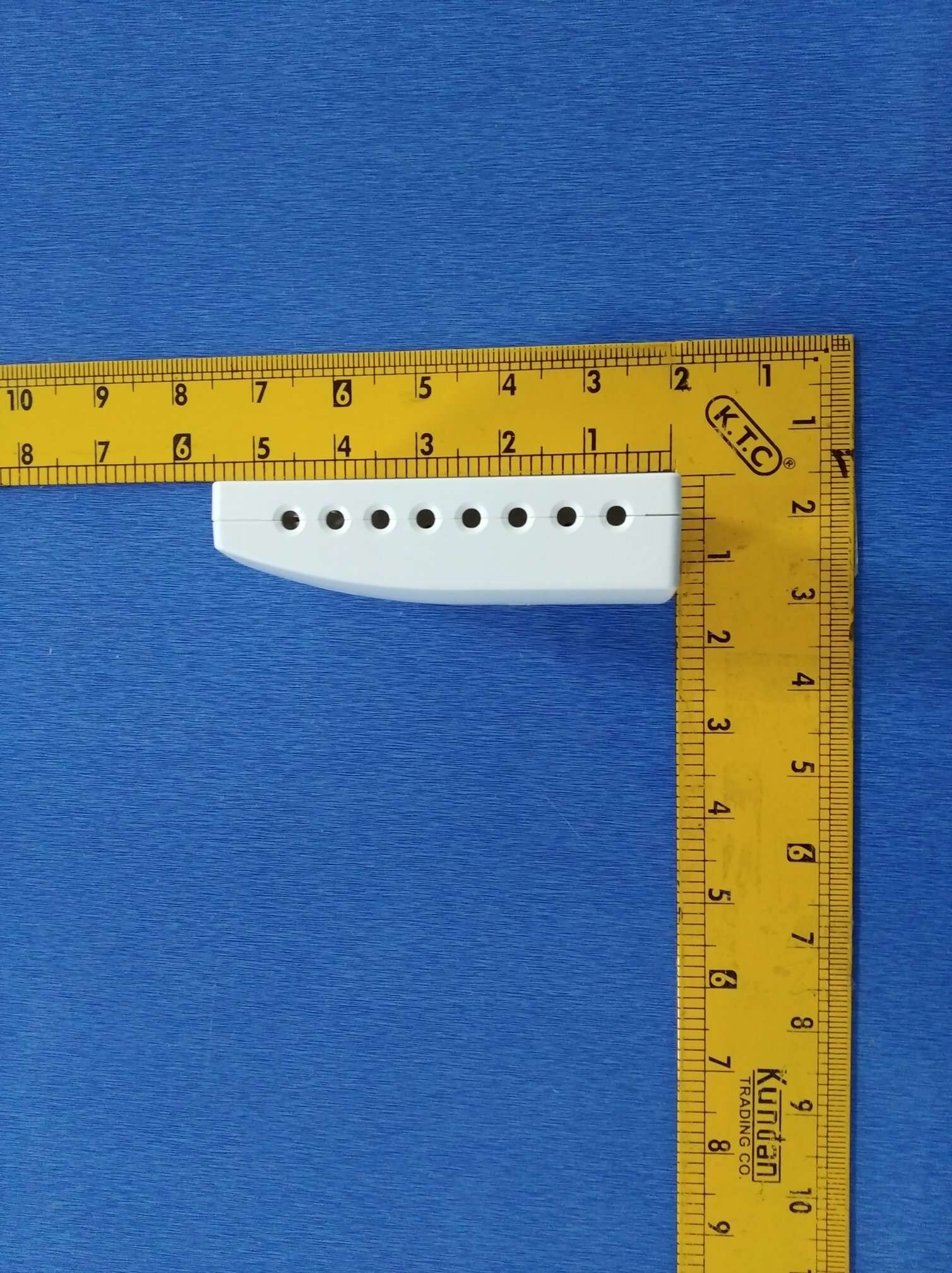
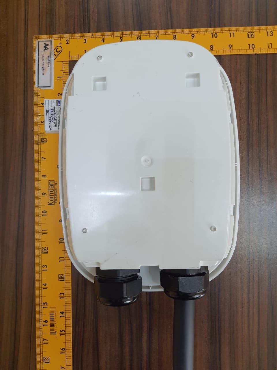
External Photos

↗

ID Label/Location Info

↗

Internal Photos

↗

RF Exposure Info

↗

Test Report

↗
↗

Test Setup Photos

↗

Document Text

Text extracted from the exhibit documents filed with the FCC. Open a document above to read the original.

Users Manual

Installation & Usage Guide WARNING - RISK OF ELECTRICAL SHOCK! Improper connection of the equipment- grounding conductor may result in a risk of electric shock, leading to death or serious injury. Emporia recommends that installation be performed by a licensed electrician or other qualified professional in accordance with the regional electrical code where it is being installed to ensure the Emporia EV Charger is properly grounded. Do not modify the provided plug – if it will not fit the outlet, have a proper outlet installed by a licensed electrician or other qualified professional. GROUNDING INSTRUCTIONS The electrical system must be grounded. If the Emporia EV Charger should malfunction or break down, grounding provides a path of least resistance for electric current to reduce the risk of electric shock. The Emporia EV Charger is equipped with a cord having an equipment grounding conductor and a grounding plug. The plug must be plugged into an appropriate receptacle that is properly installed and grounded in accordance with all local codes and ordinances. In accordance with National Electric Code, breakers should be rated for at least 125% of the Emporia EV Charger’s continuous load. Safety information Read these instructions before using the EV Charger. Charging should be supervised when used around children. Do not put fingers in EV connector. The Emporia EV Charger is intended for use with electric vehicles only. Specifically, it is intended only for electric vehicles not requiring ventilation during charging. Do not use the Emporia EV Charger in any manner other than specified in this installation guide. Do not attempt to open, disassemble, or repair any of the components of the Emporia EV Charger. There are no user serviceable parts inside. If you believe the charging station, cables, or connector gun may have been damaged in any way; do not attempt to use them. Do not install the Emporia EV Charger in environments with explosive gas or vapors; nor in damp or wet environments; nor in direct sunlight; nor where temperatures are outside its operating range of -22°F to 122°F (-30°C to 50°C)         What’s in the box Your new Emporia EV Charger contains the following items. If any of these items are missing or if you believe they’ve been damaged, call support immediately. Allen wrench Charging station 25’ charging cord Power cable with NEMA 14-50P plug SAE J1772 connector gun Mounting bracket Gun cradle Eight 7 / 32 inch #12 Phillips screws 8 drywall anchors Four M5X10 Phillips screws Before you get started Here are the tools you will need to install the EV Charger. Bubble level PencilHammer Drill with a 5/16" drill bit iOS or Android phone or tablet Phillips and flathead screwdrivers Need help? emporiaenergy.com/support [email protected] 1-844-EMPORIA (367-6742)    Step 1: Get the App Use your phone to check the signal strength of your Wi-Fi network where the EV Charger will be installed. Low/no signal may require a Wi-Fi extender for the Charger to work. Download the Emporia Energy app onto your phone or tablet from the Apple App Store, from Google Play, or from emporiaenergy.com/app. Create an account and begin the setup process. emporiaenergy.com/app EV Charger can supply a maximum charge of 48A to the EV Requires a dedicated dual pole breaker. We recommend 60A.   EV Charger can supply a maximum charge of 40A to the EV Requires a dedicated dual pole breaker. We recommend 50A. Requires a NEMA 14-50R receptacle outlet    Hardwired installation See Step 8a Plugged-in installation See Step 8b Step 2: How is the EV Charger powered? Dedicated Breaker Charge Power @ 240V 15A12A2.9kWYY 20A16A3.8kWYY 25A20A4.8kWYY 30A24A5.8kWYY 35A28A6.7kWYY 40A32A7.7kWYY 45A36A8.6kWYY 50A40A9.6kWYY 60/70/80A48A11.5kWYN 24" - 48" Allows slack for 25' cable Allows slack for 12" cable -22F 122F Step 3: Find a place for the EV Charger Locate a place to mount the EV charger where the charger is 24-48" above the floor/ground; the distance from the vehicle allows slack for 25' cable; temperatures are between -22°F to 122°F; the charger is within range of WiFi signal; if plugged-in, the distance from the NEMA outlet allows slack for a short 12" cable; and if outside, the charger is not in direct sunlight. Need help? emporiaenergy.com/support [email protected] 1-844-EMPORIA (367-6742)    24" - 48" Step 4: Mark the mounting bracket location Use a bubble level to draw a horizontal line where the top of the EV Charger will sit on the wall ensuring it is 24-48" above the floor/ground and allows slack for the 12" NEMA cable if it will be plugged in. Then, align the top of the mounting bracket to the line and mark the 4 mounting holes. Need help? emporiaenergy.com/support [email protected] 1-844-EMPORIA (367-6742)    See instructions Step 5: Install the mounting bracket For each mark, drill a 5/16" hole in the wall. Use a hammer to tap in the 4 drywall anchors. If you would like to install the gun cradle under the EV Charger, install the mounting bracket with 3 Phillips screws into the top 3 anchors, omitting the bottom screw, and go to Step 6a. If you’d like to install the gun cradle off to the side of the EV Charger, install the mounting bracket with the 4 Phillips screws into the anchors and proceed to Step 6b. Need help? emporiaenergy.com/support [email protected] 1-844-EMPORIA (367-6742)    Step 6a: Install the gun cradle under the Charger The gun cradle is designed to be installed directly under the EV Charger. If you wish to install it off to the side of the EV Charger, skip to Step 6b. Hang the gun cradle on the mounting bracket hooks. Mark the bottom mounting hole of the gun cradle. Drill a 5/16" hole in the wall at your mark. Use a hammer to tap in a drywall anchor. Install the gun cradle with 2 Phillips screws into the anchors. Need help? emporiaenergy.com/support [email protected] 1-844-EMPORIA (367-6742)    Step 6b: Install the gun cradle …

Text truncated - open the document above for the full version.

Cover Letter(s)

Agent Authorization Company: Emporia Corp. Address: 7901 SHAFFER PKWY, LITTLETON, CO 80127. Product Name: Emporia EV Charger. Model Number(s): EMEVSE1. Product Description: The Emporia EV Charging Station is a Type 1 Level 2 electric vehicle charger that charges any EV up to 40 amps with NEMA 14-50P or up to 48 amps with hardwired installation. It comes with a 25’ cable with an SAE J1772 connector so it works with all electric cars. It's IP54 enclosure is made to withstand the elements outdoors. It will get operated with input voltage of 208/240VAC 50/60Hz. Device has inbuilt Wi-Fi module of 2.4 GHz to send all data to end user via cloud. We authorize MiCOM Labs Inc., 575 Boulder Court, Pleasanton, California 94566, USA, to act on our behalf on all matters concerning the certification of above named equipment. We declare that MiCOM Labs Inc. is allowed to forward all information related to the approval and certification of equipment to the regulatory agencies as required and to discuss any issues concerning the approval application. Any and all acts carried out by MiCOM Labs on our behalf shall have the same effect as acts of our own. Signature: Date: 22-06-2021 Name: Jason Binder Title: SVP Product Development Company: Emporia Corp

Cover Letter(s)

Supplier's Declaration of Conformity 47 CFR § 2.1077 Compliance Information Unique Identifier: 2AS6P-EMEVSE1 Contact Name: Jason Binder Contact Phone: (844) 367-6742-6742 Title / Designation: SVP Product Development FCC Compliance Statement (e.g., products subject to Part 15) This device complies with Part 15 of the FCC Rules. Operation is subject to the following two conditions: (1) This device may not cause harmful interference, and (2) this device must accept any interference received, including interference that may cause undesired operation.

Internal Photos

Antenna Port 2.4g Wifi

RF Exposure Info

RF EXPOSURE EVALUATION 1. PRODUCT INFORMATION Product Description Emporia EV Charger Model Name EMEVSE1 FCC ID 2AS6P-EMEVSE1 2. EVALUATION METHOD ANDLIMIT Human exposure to RF emissions from mobile devices(47CFR§2.1091) may be evaluated based on the MPE limits adopted by the FCC for electric and magnetic field strength and/or power density, as appropriate, since exposures are assumed to occur at distances of 20 cm or more from persons. The device under test Emporia EV Charging Station is a Type 1 Level 2 electric vehicle charger that charges any EV up to 40 amps with NEMA 14-50P or up to 48 amps with hardwired installation. It comes with a 25’ cable with an SAE J1772 connector so it works with all electric cars. It's IP54 enclosure is made to withstand the elements outdoors. It will get operated with input voltage of 208/240VAC 50/60Hz. LIMITS FOR GENERAL POPULATIONIUNCONTROLLED EXPOSURE Frequency Range (MHz) E-field Strength (E) (V/m) Magnetic Field Strength (H) (A/m) Power Density(S) (mW/cm 2 ) Averaging Time IEl 2 IHl 2 or , S(Minutes) 0.3--1.34 614 1.63 (100)* 30 1.34--30 824/f 2.19/f (180/f 2 )* 30 30--300 27.5 0.073 0.2 30 300--1500 -- -- f/1500 30 1500--100,000 -- -- 1.0 30 *Note: 1. f= Frequency in MHz*Plane-wave Equivalent Power Density 2. The averaging time for General Population/Uncontrolled exposure to fixed transmitters is not applicable for mobile and portable transmitters. (operated in BT/ WIFI) See47CFR§§2.1091 and 2.1093 on source-based time-averaging requirement for mobile and portable transmitters. S=PG/4rrR 2 Where: S=power density P=power input toantenna G=power gain of the antenna in the direction of interest relative to anisotropic radiator R=distance to the center of radiation of the antenna 3. CALCULATION A minimum test separation distance 20cm is required between the antenna and radiating structures of the device and nearby persons to apply mobile device exposure limits. The distance must be at least 20cm and fully supported by the operating and installation configurations of the transmitter and its antenna(s), according to the source-based time-averaged maximum power requirements of §2.1091(d)(2). In cases where cable losses or other attenuations are applied to determine compliance, the most conservative operating configurations and exposure conditions must be evaluated. The device under test (Emporia Vue Energy Meter) is neither a mobile device nor a RF exposure product and it is not closed to 20cm distance from persons Antenna Gain (2.4GHz) = 3.05dBi (Numeric = 2.018), rr = 3.14 Frequency (MHz) Output Power (dBm) Output Power (mW) Power Density (mW/cm 2) Power Density Limit (mW/cm 2) 2412(Wi-Fi) 18.03 63.533093185 0.0255 1 2402(BLE) 1.87 1.5381546403 0.0006 1 2402(BT) 3.78 2.3878112829 0.0009 1 Note: Only the worst case recorded.

Test Report

Certificate#5593.01 Report No.: AAEMT/EMC/210413-02-01 Page | 1 Plot No.174, Udyog Vihar Phase 4, Sector -18, Gurgaon -122016, Haryana, India Contact:0124-4235350, 4145343; e-mail: info @aaemtlabs.com; Website: www.aaemtlabs.com AA Electro Magnetic Test Laboratory Private Limited FCC Test Report Part 15 subpart C FCC ID:2AS6P-EMEVSE1 Client Information: Applicant: Emporia Corp Applicant add.: 7901 SHAFFER PKWY, LITTLETON, CO 80127 Product Information: EUT Name: Emporia EV Charger Model No.: EMEVSE1 Brand Name: Emporia Energy Serial Model: N/A Standards: FCC PART 15 Subpart C: 2015 section 15.247 Prepared By: (Vaishali) AA Electro Magnetic Test Laboratory Private Limited Add. : Plot No 174, Udyog Vihar - Phase 4, Sector 18, Gurgaon, Haryana, India Date of Receipt: Apr. 13, 2021 Date of Test: May. 24~ May. 25, 2021 Date of Issue: Jun. 15, 2021 Test Result: Pass Declaration of Conformity: Declaration of conformity of the results is based as per the standard limits This device described above has been tested by AA Electro Magnetic Test Laboratory Private Limited, and the test results show that the equipment under test (EUT) is in compliance with the FCC requirements. And it is applicable only to the tested sample identified in the report. *This test report must not be used by the client to claim product endorsement by any agency of the U.S. government. Reviewed by: Approved by: Dr. Lenin Raja (Authorized Representative) (/ lenin83/) (Abhinav Kumar ) Certificate#5593.01 Report No.: AAEMT/EMC/210413-02-01 Page | 2 Plot No.174, Udyog Vihar Phase 4, Sector -18, Gurgaon -122016, Haryana, India Contact:0124-4235350, 4145343; e-mail: info @aaemtlabs.com; Website: www.aaemtlabs.com AA Electro Magnetic Test Laboratory Private Limited 1 Contents Page COVER PAGE 1 CONTENTS 2 2 VERSION 3 3 TEST SUMMARY 4 3.1 COMPLIANCE WITH FCC PART 15 SUBPART C 4 3.2 MEASUREMENT UNCERTAINTY 5 3.3 TEST LOCATION 5 4 TEST FACILITY 6 4.1 DEVIATION FROM STANDARD 6 4.2 ABNORMALITIES FROM STANDARD CONDITIONS 6 5 GENERAL INFORMATION 7 5.1 GENERAL DESCRIPTION OF EUT 7 5.2 EUT PERIPHERAL LIST 9 5.3 TEST PERIPHERAL LIST 9 6 EQUIPMENTS LIST FOR ALL TEST ITEMS 10 7 TEST RESULT 12 7.1 DESCRIPTION OF TEST CONDITIONS 12 7.2 ANTENNA REQUIREMENT 13 7.3 CONDUCTION EMISSIONS MEASUREMENT 14 7.4 RADIATED EMISSIONS MEASUREMENT 18 7.5 6 DB BANDWIDTH 42 7.6 MAXIMUM PEAK OUTPUT POWER 50 7.7 PEAK POWER SPECTRAL DENSITY 53 7.8 BAND EDGES REQUIREMENT 62 7.9 CONDUCTED SPURIOUS EMISSIONS 68 Certificate#5593.01 Report No.: AAEMT/EMC/210413-02-01 Page | 3 Plot No.174, Udyog Vihar Phase 4, Sector -18, Gurgaon -122016, Haryana, India Contact:0124-4235350, 4145343; e-mail: info @aaemtlabs.com; Website: www.aaemtlabs.com AA Electro Magnetic Test Laboratory Private Limited 2 Version Revision Record Version Chapter Date Modifier Remark -- -- -- -- -- -- -- -- -- -- -- -- -- -- -- -- -- -- -- -- Certificate#5593.01 Report No.: AAEMT/EMC/210413-02-01 Page | 4 Plot No.174, Udyog Vihar Phase 4, Sector -18, Gurgaon -122016, Haryana, India Contact:0124-4235350, 4145343; e-mail: info @aaemtlabs.com; Website: www.aaemtlabs.com AA Electro Magnetic Test Laboratory Private Limited 3 Test Summary 3.1 Compliance with FCC Part 15 subpart C TEST TEST REQUIREMENT TEST METHOD RESULT Antenna Requirement FCC PART 15 C section 15.247 (c) and Section 15.203 FCC PART 15 C section 15.247 (c) and Section 15.203 PASS Conducted Emissions at Mains Terminals FCC PART 15 C section 15.207 ANSI C63.10: Clause 6.2 PASS Radiated Spurious Emission (30 MHz to 25 GHz) FCC PART 15 C section 15.209 &15.247(d) ANSI C63.10: Clause 6.4, 6.5 and 6.6 PASS 6 dB Bandwidth FCC PART 15 C section 15.247 (a)(2) ANSI C63.10: Clause 6.9.1 PASS Maximum Peak Output Power FCC PART 15 C section 15.247(b)(3) FCC/KDB-558074 D01 v03r01 Clause 9.1.2 PASS Peak Power Spectral Density FCC PART 15 C section 15.247(e) ANSI C63.10: Clause 6.11.2.3 PASS Band Edges Measurement FCC PART 15 C section 15.247 (d) &15.205 FCC/KDB-558074 D01 v03r01 Clause 13.3.1 PASS Conducted Spurious Emission (30MHz to 25GHz) FCC PART 15 C section 15.209 &15.247(d) ANSI C63.10: Clause 6.7 PASS Remark: N/A: not applicable. Refer to the relative section for the details. EUT: In this whole report EUT means Equipment Under Test. Tx: In this whole report Tx (or tx) means Transmitter. Rx: In this whole report Rx (or rx) means Receiver. RF: In this whole report RF means Radio Frequency. ANSI C63.10: the detail version is ANSI C63.10:2013 in the whole report. Certificate#5593.01 Report No.: AAEMT/EMC/210413-02-01 Page | 5 Plot No.174, Udyog Vihar Phase 4, Sector -18, Gurgaon -122016, Haryana, India Contact:0124-4235350, 4145343; e-mail: info @aaemtlabs.com; Website: www.aaemtlabs.com AA Electro Magnetic Test Laboratory Private Limited 3.2 Measurement Uncertainty All measurements involve certain levels of uncertainties, the following measurements uncertainty Levels have estimated based on standards, the maximum value of the uncertainty as below: No. Item Uncertainty 1 Conducted Emission Test 2.67dB 2 Radiated Emission Test 3.06dB 3.3 Test Location All tests were performed at: AA Electro Magnetic Test Laboratory Private Limited Plot No 174, Udyog Vihar - Phase 4, Sector 18, Gurgaon, Haryana, India Tel.: +91-0124-4235350 Certificate#5593.01 Report No.: AAEMT/EMC/210413-02-01 Page | 6 Plot No.174, Udyog Vihar Phase 4, Sector -18, Gurgaon -122016, Haryana, India Contact:0124-4235350, 4145343; e-mail: info @aaemtlabs.com; Website: www.aaemtlabs.com AA Electro Magnetic Test Laboratory Private Limited 4 Test Facility The test facility is recognized, certified or accredited by the following organizations: ILAC / NABL Accreditation No.: TC-8597 Three 3m Semi-Anechoic Chamber, 1 full-Anechoic chamber and 2 Shielding Rooms of AA Electro Magnetic Test Laboratory Private Limited have been registered by National Accreditation Board for Testing and Calibration Laboratories (NABL). ILAC –A2LA Accreditation No.: 5593.01 Three 3m Semi-Anechoic Chamber, 1 full-Anechoic c…

Text truncated - open the document above for the full version.

Test Report

Certificate#5593.01 Report No.: AAEMT/EMC/210413-02-02 Page | 1 Plot No.174, Udyog Vihar Phase 4, Sector -18, Gurgaon -122016, Haryana, India Contact: 0124-4235350, 4145343; e-mail: info @aaemtlabs.com; Website: www.aaemtlabs.com AA Electro Magnetic Test Laboratory Private Limited FCC Test Report Part 15 subpart C Client Information: Applicant: Emporia Corp Applicant add.: 7901 SHAFFER PKWY, LITTLETON, CO 80127 Product Information: EUT Name: Emporia EV Charger Model No.: EMEVSE1 Brand Name: Emporia Energy FCC ID: 2AS6P-EMEVSE1 Standards: FCC PART 15 Subpart C: 2013 section 15.247 Prepared By: (Vaishali) AA Electro Magnetic Test Laboratory Private Limited Add. : Plot No 174, Udyog Vihar - Phase 4, Sector 18, Gurgaon, Haryana, India Date of Receipt: Apr. 13, 2021 Date of Test: May. 25~ May. 27, 2021 Date of Issue: Jun. 15, 2021 Test Result: Pass This device described above has been tested by AA Electro Magnetic Test Laboratory Private Limited, and the test results show that the equipment under test (EUT) is in compliance with the FCC requirements. And it is applicable only to the tested sample identified in the report. *This test report must not be used by the client to claim product endorsement by any agency of the U.S. government. Reviewed by: Approved by: Dr. Lenin Raja (Authorized Representative) (/ lenin83/) (Abhinav Kumar ) Certificate#5593.01 Report No.: AAEMT/EMC/210413-02-02 Page | 2 Plot No.174, Udyog Vihar Phase 4, Sector -18, Gurgaon -122016, Haryana, India Contact: 0124-4235350, 4145343; e-mail: info @aaemtlabs.com; Website: www.aaemtlabs.com AA Electro Magnetic Test Laboratory Private Limited 1 Contents Page COVER PAGE 1 CONTENTS ..................................................................................................................................................................... 2 2 TEST SUMMARY ........................................................................................................................................................... 4 2.1 COMPLIANCE WITH FCC PART 15 SUBPART C ............................................................................................................... 4 2.2 TEST LOCATION ........................................................................................................................................................... 5 2.3 MEASUREMENT UNCERTAINTY .................................................................................................................................... 5 3 TEST FACILITY ............................................................................................................................................................. 6 3.1 DEVIATION FROM STANDARD ....................................................................................................................................... 6 3.2 ABNORMALITIES FROM STANDARD CONDITIONS ............................................................................................................ 6 4 GENERAL INFORMATION .......................................................................................................................................... 7 4.1 GENERAL DESCRIPTION OF EUT................................................................................................................................... 7 4.2 DESCRIPTION OF TEST CONDITIONS .............................................................................................................................. 9 4.3 TEST PERIPHERAL LIST .............................................................................................................................................. 10 4.4 EUT PERIPHERAL LIST .............................................................................................................................................. 10 5 EQUIPMENTS LIST FOR ALL TEST ITEMS ........................................................................................................... 11 6 TEST RESULT .............................................................................................................................................................. 13 6.1 ANTENNA REQUIREMENT ........................................................................................................................................... 13 6.1.1 Standard requirement ........................................................................................................................................ 13 6.1.2 EUT Antenna .................................................................................................................................................... 13 6.2 CONDUCTION EMISSIONS MEASUREMENT ................................................................................................................... 14 6.2.1 Applied procedures / Limit ................................................................................................................................ 14 6.2.2 Test procedure .................................................................................................................................................. 14 6.2.3 Test results ........................................................................................................................................................ 15 6.3 RADIATED EMISSIONS MEASUREMENT ....................................................................................................................... 17 6.3.1 Applied procedures / Limit ................................................................................................................................ 17 6.3.2 Test setup.......................................................................................................................................................... 17 6.3.3 Test procedure .................................................................................................................................................. 19 6.3…

Text truncated - open the document above for the full version.

Test Setup Photos

Radiated Spurious Emission Test Setup Below 1GHz: Above 1GHz: Conducted Emission Test Setup

Contact Information

Applicant

Jason Binder(CTO Hardware)
[email protected]2252054813Fax: 3039999999

Technical Contact

Emporia Corp

United States

Test Firm

AA Electro Magnetic Test LaboratoryJackie Deng
[email protected]911244235350

Technical Specifications

#Rule PartsFrequency RangePower Output
215C2.40 GHz - 2.48 GHz2.20 mW
Confidentiality
Long Term
Grant Notes
Output power listed is conducted power. This device contains 20 and 40 MHz signal bandwidth. The antenna used with this transmitter must be installed to provide a minimum separation distance of at least 20 cm from all persons and must not be co-located or operating in conjunction with any other antenna or transmitter, except in accordance with FCC multi- transmitter product procedures. End-users must be provided with operating procedures for satisfying RF exposure compliance.

Other Applications from Emporia Corp

Smart Home Energy Monitor - FCC ID 2AS6P-EMCTV2 - Emporia Corp
2AS6P-EMCTV2

Smart Home Energy Monitor

Sep 26, 2020

Equipment Class

DTS - Digital Transmission System