2AT6QTKP8600Network Wall Pad
Summit Technology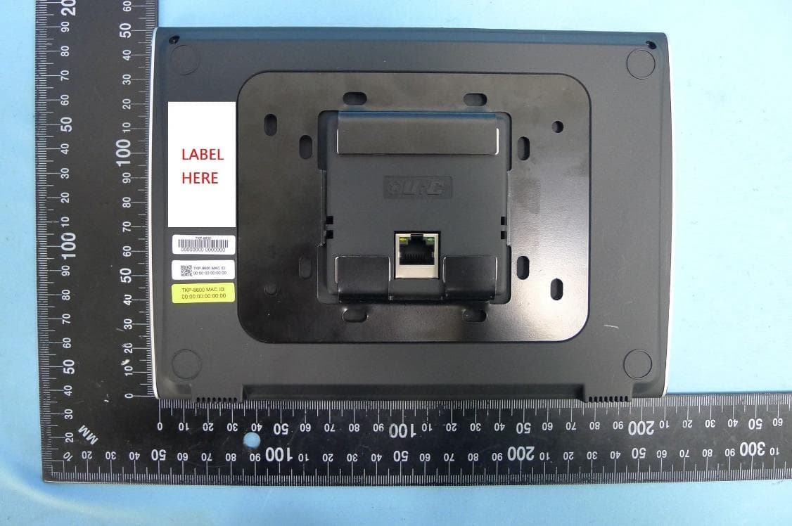
Click to zoom
Application Details
- Equipment Class
- DTS - Digital Transmission System
- Date of Grant
- Dec 30, 2020
- Application Purpose
- Original Equipment
- Date of Application
- Dec 29, 2020
- Equipment Note
- Network Wall Pad
- Frequency Range
- 2402.00000000 - 2480.00000000
- Company
- Summit Technology
- Country
- South Korea
Documents & Files
Document Text
Text extracted from the exhibit documents filed with the FCC. Open a document above to read the original.
Users Manual
TKP-8600 Owner’s Manual Total Control TKP-8600 Owner’s Manual Total Control TKP-8600 Owner’s Manual Table � C�tents Coming So�! 1 Total Control TKP-8600 Owner’s Manual Introducing the TKP-8600 Thank you for purchasing URC’s TKP-8600 in-wall network keypad. Ideal for residential and commercial installations, this slick in-wall touchscreen features a brilliant 8” LCD screen to display vivid images, easy control, and live video from door stations/surveillance cameras. The native Audio Video Intercomoffers convenient room-to-room communication with live video is 1080p resolution. Install multiple intercom-enabled devicesin the home or business to make communication across each zone easy. A built-in microphone provides easy voice communication and control using Amazon Alexaand/or Siri(via Apple TV two-way module). Features & Benefits • Amazon Alexa Push to Talk Functionality:Push-button microphone via built in speaker allowing for voice control and feedback. • 8” Capacitive LCD Screen:Displays vivid and colorful custom menus, backgrounds, images, icons and more. Speak with a certified URC Integrator for personalized backgrounds, room, and scene images! • Live Camera View:View integrated MJPEG and/or H264 camerastreams directly on the TKP-8600. The keypad’s built-in cameracan be viewed locally or remotely! • Proximity Sensor with Automation Events:The TKP-8600’s advanced proximity sensor wakes the device up as you approach it. Speak with a certified URC Integrator about the possibility of triggering custom events when the proximity sensor is tripped. • HDA Streaming:Natively stream Alexa and Amazon audio services via an integrated HDA system. This allows you to steam Amazon Music, Audible, or your favorite Amazon audio service directly through your system’s HDA audio. • Native Audio Video Intercom:Make calls audio or audio-video calls throughout the system with other TKP-8600s or intercom enabled keypads. • Portrait or Landscape Mode:The TKP-8600 can be displayed in either Portrait or Landscape mode and is installed in a standard three-gangor dual gangwall box. 2 Total Control TKP-8600 Owner’s Manual Parts List The following is included in the box: 3 Total Control TKP-8600 Owner’s Manual TKP-8600 Installation Guidelines The TKP-8600 can be iinstalled in a standard three-gangor dual gangwall box. Releasing the Tamper Resistant Lock 1. Prior to installing the TKP-8600, ALWAYS make sure the tamper lock has been released. Failing to do so could cause physical damage to the TKP-8600. The lock is located at the topof the TKP-8600 and requires a special tool (included in the box) to unlock. To unlock the TKP-8600 use the supplied unlock tool to hook into the lock and gently lift up. The lock remains recessed and the device can be installed. 4 Total Control TKP-8600 Owner’s Manual New Construction The TKP-8600 fitsinto any 3-gang or 2-gang box. However, there are certain aspects of the installation that must be highlighted. 1. Measure the 3-gang or 2-gang box and using your preferred cutting tool, cut a hole in the wall that matches the measurementsof the gang box. 2. Install the 3-gang or 2-gang box into the cut out and securely tighten all the necessary screws. 3. Align the mounting bracket with the appropriate slots on the 3-gang or 2-gang box. Using thesupplied screws, securely tighten the mounting bracket on the 3-gang or 2-gang box. 4. Install the TKP-8600 onto the mounting bracket. TheTKP-8600 is equipped with magnets that make the installation process easier and more secure. 5. Push down the tamper resistant lockto lock the TKP-8600 in place, keep in mind the supplied removal tool is needed to open the lock. Wall 2-Gang Box MOUNTING BRACKET 5 Total Control TKP-8600 Owner’s Manual For Retrofit Boxes Installing the TKP-8600 into a retrofitted 3-gang or 2-gang boxis easy. The mounting plate must be installed directly onto the 3-gang/2-gang box. The frame of the retrofit box provides ample space for the TKP-8600 to mount properly on the mounting plate. The mounting place is magnetic and attaches to the back of the TKP-8600 easily. Prior to installing the TKP-8600, assure that the lock is disengaged. Mounting Plate Orientation Notice the orientation of the mounting plate. The image at the right has the mounting plate installed on a 2-gang retrofit box. When installing This portion connects and holds the TKP-8600 in place. It must be positioned as seen here. 6 Total Control TKP-8600 Owner’s Manual Navigating the Main Menu Although the specific screen design and button option are dictated by your certified URC integrator, the general layout remains the same amongst URC interfaces. Navigating across pages is performed through screen swipes: • Swipe Left:Reveals additional Main Menu pages, the total amount of pages is determined by the URC programmer and can be customized. • Swipe Right:When on the first page of the Main Menu, swiping right navigates the user to the Scenes Menu(if programmed). For more information on the Scenes Menu, speak to your certified URC integrator. • Button Tapping:Perform a singe-tapon any button on the TKP-8600 to perform its programmed function. • Press-n-Hold:Certain buttons require a specific button press. These buttons require the user to press and hold the icon down for three or more seconds to perform the programmed action. Below are description of page elements you can interact with: 1. Category/Device Ribbon:Select a Category(i.e. Entertainment) to reveal the associated submenu or select a device(i.e. Cable Box) to access that device’s control menu. The buttons available here are dictated by the URC programmer. 2. Rooms Menu:Select the Room/Zone name to access the system’s Rooms Menu. This menu allows the end-user to select and control another area in the system. 3. Volume Control:Tap the minus (-) button to decrease the volume or the plus (+) button to increase it. Press the mute button to toggle the functionality on/off. 4. Page Indicators: Signify one of the follow…
Text truncated - open the document above for the full version.
External Photos
Report No.: 2010TWE201-U2 Product: Network Wall Pad Brand Name: URC (Universal Remote Control, Inc) Model Number: TKP-8600 1 of 3 External Photograph (1) EUT Photo (2) EUT Photo Report No.: 2010TWE201-U2 2 of 3 (3) EUT Photo (4) EUT Photo Report No.: 2010TWE201-U2 3 of 3 (5) EUT Photo (6) EUT Photo
Internal Photos
Report No.: 2010TWE201-U2 Product: Network Wall Pad Brand Name: URC (Universal Remote Control, Inc) Model Number: TKP-8600 1 of 8 Internal Photograph (1) EUT Photo (2) EUT Photo Report No.: 2010TWE201-U2 2 of 8 (3) EUT Photo (4) EUT Photo Report No.: 2010TWE201-U2 3 of 8 (5) EUT Photo (6) EUT Photo Report No.: 2010TWE201-U2 4 of 8 (7) EUT Photo (8) EUT Photo Report No.: 2010TWE201-U2 5 of 8 (9) EUT Photo (10) EUT Photo Report No.: 2010TWE201-U2 6 of 8 (11) EUT Photo (12) EUT Photo Report No.: 2010TWE201-U2 7 of 8 (13) EUT Photo (14) EUT Photo Report No.: 2010TWE201-U2 8 of 8 (15) EUT Photo (16) EUT Photo
RF Exposure Info
MRT Technology (Taiwan) Co., Ltd Report No.: 2010TWE201-U3 Phone: +886-3-3288388 Repor t Vers ion: 1.0 Fax: +886-3-3288918 Issue Date: 2020-11-06 Web: www.mrt-cert.com FCC ID: 2AT6QTKP8600 Page Number: 1 of 6 RF Exposure Evaluation Declaration FCC ID: 2AT6QTKP8600 APPLICANT: Summit Technology Application Type: Certification Product: Network Wall Pad Model No.: TKP-8600 Brand Name: URC (Universal Remote Control, Inc) FCC Rule Part(s): Part 2.1093 (Portable) Received Date: October 8, 2020 Test Date: October 13~November 2, 2020 Reviewed By : ( Paddy Chen ) Approved By : ( Chenz Ker ) The test results relate only to the samples tested. This equipment has been shown to be capable of compliance with the applicable technical standards as indicated in the measurement report. Test results reported herein relate only to the item(s) tested. The test report shall not be reproduced except in full without the written approval of MRT Technology (Taiwan) Co., Ltd. Report No.: 2010TWE201-U3 FCC ID: 2AT6QTKP8600 Page Number: 2 of 6 Revision History Report No. Version Description Issue Date Note 2010TWE201-U3 1.0 Original Report 2020-11-06 Report No.: 2010TWE201-U3 FCC ID: 2AT6QTKP8600 Page Number: 3 of 6 1. PRODUCT INFORMATION 1.1. Equipment Description 1.2. Antenna Description No. Manufacturer Part No. Antenna Type Peak Gain 1 BRITO WF-EM-2006-0817-A PCB 2.0dBi Product Name Network Wall Pad Model No. TKP-8600 Brand Name URC (Universal Remote Control, Inc) Bluetooth Specification Bluetooth Mode: V4.0 LE Operating Frequency 2402~2480MHz Modulation Type GFSK Report No.: 2010TWE201-U3 FCC ID: 2AT6QTKP8600 Page Number: 4 of 6 2. MAXIMUM PERMISSIBLE EXPOSURE (MPE) 2.1. FCC Limits According to FCC KDB 447498 Section 4.3 - General SAR test exclusion guidance For 100 MHz to 6 GHz and test separation distances ≤ 50 mm, the 1-g and 10-g SAR test exclusion thresholds are determined by the following: [(max. power of channel, including tune-up tolerance, mW) / (min. test separation distance, mm)] · [√f(GHz)] ≤ 3.0 for 1-g SAR, and ≤ 7.5 for 10-g extremity SAR, where 1. f(GHz) is the RF channel transmit frequency in GHz 2. Power and distance are rounded to the nearest mW and mm before calculation 3. The result is rounded to one decimal place for comparison 4.The values 3.0 and 7.5 are referred to as numeric thresholds in step b) below The test exclusions are applicable only when the minimum test separation distance is ≤ 50 mm, and for transmission frequencies between 100 MHz and 6 GHz. When the minimum test separation distance is < 5 mm, a distance of 5 mm according to 4.1 f) is applied to determine SAR test exclusion. Report No.: 2010TWE201-U3 FCC ID: 2AT6QTKP8600 Page Number: 5 of 6 2.2. IC Limits Output power level shall be the higher of the maximum conducted or equivalent isotropically radiated power (e.i.r.p.) source-based, time-averaged output power. For controlled use devices where the 8 W/kg for 1 gram of tissue applies, the exemption limits for routine evaluation in Table 1 are multiplied by a factor of 5. For limb-worn devices where the 10 gram value applies, the exemption limits for routine evaluation in Table 1 are multiplied by a factor of 2.5. If the operating frequency of the device is between two frequencies located in Table 1, linear interpolation shall be applied for the applicable separation distance. For test separation distance less than 5 mm, the exemption limits for a separation distance of 5 mm can be applied to determine if a routine evaluation is required. Frequency (MHz) Exemption Limits (mW) At separation distance of ≤5 mm At separation distance of 10 mm At separation distance of 15 mm At separation distance of 20 mm At separation distance of 25 mm 300 71 mW 101 mW 132 mW 162 mW 193 mW 450 52 mW 70 mW 88 mW 106 mW 123 mW 835 17 mW 30 mW 42 mW 55 mW 67 mW 1900 7 mW 10 mW 18 mW 34 mW 60 mW 2450 4 mW 7 mW 15 mW 30 mW 52 mW 3500 2 mW 6 mW 16 mW 32 mW 55 mW 5800 1 mW 6 mW 15 mW 27 mW 41 mW Frequency (MHz) At separation distance of 30 mm At separation distance of 35 mm At separation distance of 40 mm At separation distance of 45 mm At separation distance of ≥50 mm ≤300 223 mW 254 mW 284 mW 315 mW 345 mW 450 141 mW 159 mW 177 mW 195 mW 213 mW 835 80 mW 92 mW 105 mW 117 mW 130 mW 1900 99 mW 153 mW 225 mW 316 mW 431 mW 2450 83 mW 123 mW 173 mW 235 mW 309 mW 3500 86 mW 124 mW 170 mW 225 mW 290 mW 5800 56 mW 71 mW 85 mW 97 mW 106 mW Table 1: SAR evaluation – Exemption limits for routine evaluation based on frequency and separation distance. Report No.: 2010TWE201-U3 FCC ID: 2AT6QTKP8600 Page Number: 6 of 6 2.3. Test Result Mode Frequency Band (MHz) Output Power (dBm) Output Power (mW) FCC Extremity SAR Test Exclusion Threshold (mW) BLE 2402~2480 5.98 3.96 10 So, this device can complies the SAR test exclusion. The End
Test Report
MRT Technology (Taiwan) Co., Ltd Report No.: 2010TWE201-U2 Phone: +886-3-3288388 Report Version: 1.0 Fax: +886-3-3288918 Issue Date: 2020-11-06 Web: www.mrt-cert.com FCC ID: 2AT6QTKP8600 Page Number: 1 of 51 FCC ID: 2AT6QTKP8600 APPLICANT: Summit Technology Application Type: Certification Product: Network Wall Pad Model No.: TKP-8600 Brand Name: URC (Universal Remote Control, Inc) FCC Classification: (DTS) Digital Transmission System FCC Rule Part(s): Part 15.247 Test Procedure(s): ANSI C63.10-2013 Received Date: October 8, 2020 Test Date: October 13~November 2, 2020 MEASUREMENT REPORT FCC PART 15.247 Bluetooth V4.0 LE The test results only relate to the tested sample. This equipment has been shown to be capable of compliance with the applicable technical standards as indicated in the measurement report and was tested in accordance with the measurement procedures specified in ANSI C63.10. Test results reported herein relate only to the item(s) tested. The test report shall not be reproduced except in full without the written approval of MRT Technology (Taiwan) Co., Ltd. Tested By : ( Peter Syu ) Reviewed By : ( Paddy Chen ) Approved By : ( Chenz Ker) Report No.: 2010TWE201-U2 FCC ID: 2AT6QTKP8600 Page Number: 2 of 51 Revision History Report No. Version Description Issue Date Note 2010TWE201-U2 1.0 Original Report 2020-11-06 Report No.: 2010TWE201-U2 FCC ID: 2AT6QTKP8600 Page Number: 3 of 51 CONTENTS Description Page §2.1033 General Information ......................................................................................................... 5 1. INTRODUCTION ..................................................................................................................... 6 1.1. Scope .................................................................................................................................... 6 1.2. MRT Test Location ................................................................................................................ 6 2. PRODUCT INFORMATION ..................................................................................................... 7 2.1. Equipment Description .......................................................................................................... 7 2.2. Product Specification Subjective to this Standard .................................................................. 8 2.3. Test Mode ............................................................................................................................. 8 2.4. Operation Frequency / Channel List ...................................................................................... 9 2.5. Test Configuration ............................................................................................................... 10 2.6. Test Software ...................................................................................................................... 10 2.7. EMI Suppression Device(s)/Modifications ........................................................................... 10 2.8. Labeling Requirements ....................................................................................................... 10 3. DESCRIPTION of TEST ......................................................................................................... 11 3.1. Evaluation Procedure .......................................................................................................... 11 3.2. AC Line Conducted Emissions ............................................................................................ 11 3.3. Radiated Emissions ............................................................................................................ 12 4. ANTENNA REQUIREMENTS ................................................................................................ 13 5. TEST EQUIPMENT CALIBRATION DATE ............................................................................ 14 6. MEASUREMENT UNCERTAINTY ......................................................................................... 15 7. TEST RESULT ...................................................................................................................... 16 7.1. Summary ............................................................................................................................. 16 7.2. 6dB Bandwidth Measurement ............................................................................................. 17 7.2.1. Test Limit ......................................................................................................................... 17 7.2.2. Test Procedure used ....................................................................................................... 17 7.2.3. Test Setting ..................................................................................................................... 17 7.2.4. Test Setup ....................................................................................................................... 17 7.2.5. Test Result ...................................................................................................................... 18 7.3. Output Power Measurement ................................................................................................ 19 7.3.1. Test Limit ......................................................................................................................... 19 7.3.2. Test Procedure Used ....................................................................................................... 19 7.3.3. Test Setting ..................................................................................................................... 19 7.3.4. Test Setup ....................................................................................................................... 19 7.3.5. Test Result of Output Power ....................................................................................…
Text truncated - open the document above for the full version.
Test Setup Photos
Report No.: 2010TWE201-U2 Product: Network Wall Pad Brand Name: URC (Universal Remote Control, Inc) Model Number: TKP-8600 1 of 3 Test Photograph Test Mode: Mode 1 Description: Front View of Conducted Emission Test Setup Test Mode: Mode 1 Description: Back View of Conducted Emission Test Setup Report No.: 2010TWE201-U2 2 of 3 Test Mode: Mode 1 Description: Radiated Emission Test Setup for below 1GHz Test Mode: Mode 1 Description: Radiated Emission Test Setup for above 1GHz Report No.: 2010TWE201-U2 3 of 3 Test Mode: Mode 1 Description: Conducted Emission Test Setup
Contact Information
Applicant
Yong-Seong Park(Senior Director)
Test Firm
MRT Technology (Taiwan) Co.,LtdChenz Ker
Technical Specifications
| # | Rule Parts | Frequency Range | Power Output |
|---|---|---|---|
| 1 | 15C | 2.40 GHz - 2.48 GHz | 4.00 mW |
Other Applications from Summit Technology
2AT6QTDC8300
Jul 02, 2024Touch Screen Controller
Equipment Class
DTS - Digital Transmission System
2AT6QTDC5100
Jan 19, 2023Touch Screen Controller
Equipment Class
DTS - Digital Transmission System
2AT6QMRX12
Jul 28, 2021BASE-STATION
Equipment Class
JAB - Part 15 Class B Digital Device
2AT6QMX790
May 12, 2021RF Remote controller
Equipment Class
DSR - Part 15 Remote Control/Security Device Transceiver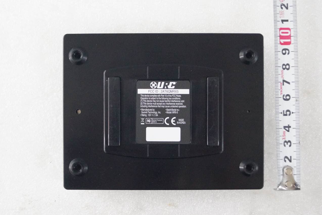
2AT6QMRX5
Aug 09, 2020BASE-STATION
Equipment Class
JAB - Part 15 Class B Digital Device