2AT6XLITERADIO2RC Radio Transmitters
Shenzhen Baida Moxing Co.,Ltd.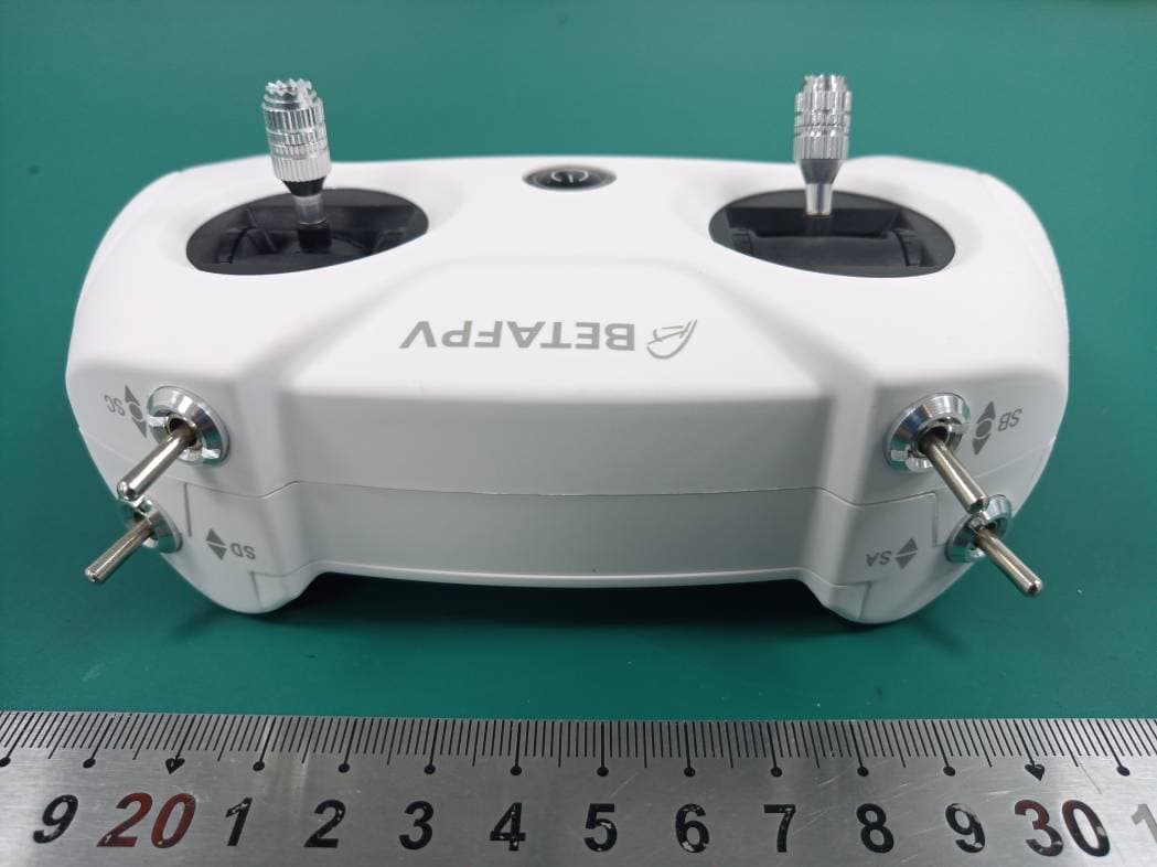
Click to zoom
Application Details
- Equipment Class
- DSS - Part 15 Spread Spectrum Transmitter
- Date of Grant
- Apr 27, 2021
- Application Purpose
- Original Equipment
- Date of Application
- Apr 27, 2021
- Equipment Note
- RC Radio Transmitters
- Frequency Range
- 2403.70000000 - 2473.90000000
- Country
- China
Documents & Files
Document Text
Text extracted from the exhibit documents filed with the FCC. Open a document above to read the original.
Users Manual
CONTENT Installing the Tramsmitter Battery Power the Transmitter On and Off Switching Protocol Binding the Receiver Battery Alarm & Charge the Battery HID Joystick Student Radio Mode OpenTX Companion FAQ The front side of the radio. The back side of the radio. Installing the Transmitter Battery 1. Remove battery cover from the back of the transmitter. 2. Connect the included 2 piece 1S batteries to the power cable, and insert the connector to the transmitter. 3. Install the battery cover. Power the Transmitter On and Off 1.Press the power button until the transmitter shake twice, then release the power button. The LED will be green first, and turn to blue finally. 2.Press the power button until the transmitter shake once, then it will turn off. Switching Protocol Press and hold the bind button, then press the power button until the purple light is flashing. LED StatusProtocol Version Flash onceD16(FCC) Flash twiceD16(EU) Flash Three TimesD8 Binding the Receiver LED StatusReasonSolution Red Solid The throttle stick or switches are not in the lowest Lower throttle and sw to the lowest positio to blue then. Green SolidThe system is loading. Wait for the system l completes Blue Flash Slow Battery reaches the low voltage limit Charging the batteri 1. Make sure the transmitter is powered on. 2. Press the BIND button from the back of the transmitter. The transmitter will enter the binding mode and last about 10 seconds, indicated by blue and red LED flash alternately. 3. Check the receiver if binding successfully. If not, redo the process above. Battery Alarm & Charge the Battery The blue LED flashes slowly when the battery reaches the low voltage limit. Plug in USB for charging. HID Joystick The LiteRadio 2 transmitter can act as a USB Joystick when connected to a personal computer. The below steps describe how to activate this function. 1. Power on the transmitter, ensure the LED is solid blue. 2. Connect USB cable, USB connect symbol appears. 3. USB Joystick device should be available on computer. The OpenTX manual of how to setup the joystick function. https://opentx.gitbooks.io/manual-for-opentx-2-2/radio_joystick.html Student Radio Mode The trainer function is available for this LiteRadio 2 transmitter. Inserting the audio cable to the audio port, LiteRadio transmitter could be recogniz ed as the student radio in default. The OpenTX manual of how to setup the trainer function. https://opentx.gitbooks.io/manual-for-opentx-2-2/radio_trainer.html OpenTX Companion The LiteRadio 2 transmitter runs the OpenTX 2.2.4 firmware. OpenTX comes with a computer-based graphical user interface, OpenTX Companion, that runs on Windows, Mac OS and Linux. First, please download the OpenTX Companion file and install it in your computer. Please DO NOT use the original version. https://github.com/BETAFPV/opentx/blob/LiteRadio/companion/ companion-windows-2.2.4.exe How to connect the transmitter to the OpenTX Companion: 1. Press and hold the SETUP button from the back of the transmitter. 2. Press the power button on the transmitter. And then release both buttons. The LED ring will not power on . 3. Connect the transmitter to the computer via a USB cable. 4. Open the OpenTX Companion software. 5. Set the radio type to Lite Radio in the settings page. As show below. Do not forget to press the OK button at the end of this tab. 6. Press the second button on the left column to read models and settings from the radio. If you get a document dialogue as show below. Congratulate, connect successfully. The frequent usage of the OpenTX Companion is trim the gimbal central value. For example, You find the center value of the gimbal on the roll axis is 1525 in the Betaflight Configuration. The central value of the gimbal in the range of 1500+-5 is normal. 1. Click the Edit Radio Settings in the dialog above. In the pop new dialog, choose the Calibration tab. As show below. 2. Calculate the calibrated Mid Value according to the equation below. Calibrated Mid Value = Original Mid Value + ( Betaflight Configuration Mid Value - 1500) * 2 Calibrated Mid Value = 1010 + (1525 - 1500)*2 = 1060 3. Update the Ail (Roll) Mid Value to 1060 and click the Write Models. button in the end of the tab. The table above is just for the Mode 1 ( right hand throttle). So if you have a Mode 2 radio transmitter (left hand throttle), if you want to calibrate the pitch value, you must change the Mid Value in Throttle row. 4. Now back to the Betaflight Configuration, confirm if the gimbal calibra tion works. FAQ Q: What is the expected range from the LiteRadio V2 transmitter? A: The average output power is about 80mW on the transmitter. Also the valid range of the radio transmitter depends on the receiver. This is our testing use this LiteRadio V2 transmitter. Q: Is it possible to flash the radio to a different protocol? If I want to try D8 or Bayang instead? A: No. We should change the RF components in the transmitter for a different protocol. Q: Is it possible to change radio to mode 1 from mode 2? A: We think it is not easy for customers to change the mode. Need some modification. We should open the transmitter covers and exchange the gimbals first. Then we should update the configuration via the OpenTX Companion. So NOT recommend. ReceiverFPV DronesRange Integrated SPI Frsky D16 receiver Meteor65200m External XM+ receiver HX100600m External AC900 receiver 75X HD600m FCC Caution: Any Changes or modifications not expressly approved by the party responsible for compliance could void the user's authority to operate the equipment. This device complies with part 15 of the FCC Rules. Operation is subject to the following two conditions: (1) This device may not cause harmful interference, and (2) this device must accept any interference received, including interference that may cause undesired operation. IMPORTANT NOTE: Note: This equipment has been tested and found to comply with the limits for a Class B digital device, pursuant to part 15 of the FCC Rul…
Text truncated - open the document above for the full version.
Cover Letter(s)
Shenzhen Baida Moxing Co.,Ltd. ADD: 2007 Building 11, Tianan Yungu Phase II, Bantian Street, Longgang District, Shenzhen, China Tel: +8618676697125 Mail: [email protected] DECLARATION OF SIMILARITY Date: 2021-04-15 FEDERAL COMMUNICATIONS COMMISSIONS Authorization and Evaluation Division 7435 Oakland Mills Road Columbia, MD 21046 Dear Sir/Madam, We, Shenzhen Baida Moxing Co.,Ltd. hereby declare that our product: RC Radio Transmitters (model : Literadio 2, FCC ID: 2AT6XLITERADIO2) has the following series models: Literadio 2 SE. The difference between the Literadio 2 and the Literadio 2 SE is that only model name is different , Others all the same. Yours sincerely, Signature: Nie Yong Manager
Cover Letter(s)
Shenzhen Baida Moxing Co.,Ltd. ADD: 2007 Building 11, Tianan Yungu Phase II, Bantian Street, Longgang District, Shenzhen, China Tel: +8618676697125 Mail: [email protected] QA-FR-171-A FCC Confidential Authorization 2021-3- 15 FEDERAL COMMUNICATIONS COMMISSIONS Authorization and Evaluation Division 7435 Oakland Mills Road Columbia, MD 21046 Subject: Confidentiality Request regarding application for certification of FCC ID: 2AT6XLITERADIO2 In accordance with Sections 0.457 and 0.459 of the Commission’s Rules, Shenzhen Baida Moxing Co.,Ltd. hereby requests long-term confidential treatment of information accompanying this application as outlined below: • Block Diagram • Schematics • Operation Description The above materials contain proprietary and confidential information not customarily released to the public. The public disclosure of these materials provides unjustified benefits to its competitors in the market. Sincerely Yours, Signature: Nie Yong Manager
External Photos
Bay Area Compliance Laboratories Corp. (Shenzhen) Project No.: RSZ200413817-RF Page 1 of 3 EXHIBIT B - EUT EXTERNAL PHOTOGRAPHS Bay Area Compliance Laboratories Corp. (Shenzhen) Project No.: RSZ200413817-RF Page 2 of 3 Bay Area Compliance Laboratories Corp. (Shenzhen) Project No.: RSZ200413817-RF Page 3 of 3
ID Label/Location Info
Bay Area Compliance Laboratories Corp. (Shenzhen) Project No.: RSZ200413817-RF EXHIBIT A - FCC ID LABEL AND LOCATION FCC ID Label FCC ID Label Location Information The label shown shall be permanently affixed at a conspicuous location on the device and be readily visible to the user at the time purchase (Labeling requirements per 2.925)
Internal Photos
Bay Area Compliance Laboratories Corp. (Shenzhen) Project No.: RSZ200413817-RF Page 1 of 4 EXHIBIT C - EUT INTERNAL PHOTOGRAPHS Bay Area Compliance Laboratories Corp. (Shenzhen) Project No.: RSZ200413817-RF Page 2 of 4 Bay Area Compliance Laboratories Corp. (Shenzhen) Project No.: RSZ200413817-RF Page 3 of 4 PCB Antenna was Disconnect Bay Area Compliance Laboratories Corp. (Shenzhen) Project No.: RSZ200413817-RF Page 4 of 4 Antenna
Test Report
Note: This report may contain data that are not covered by the A2LA accreditation and are marked with an asterisk “★”. BACL is not responsible for the authenticity of any test data provided by the applicant. Data included from the applicant that may affect test results are marked with an asterisk ’*’. Customer model name, addresses, names, trademarks etc. are not considered data. This report cannot be reproduced except in full, without prior written approval of the Company. Unless otherwise stated the results shown in this test report refer only to the sample(s) tested. This report is valid only with a valid digital signature. The digital signature may be available only under the Adobe software above version 7.0. FCC PART 15.247 TEST REPORT For Shenzhen Baida Moxing Co.,Ltd. 2007 Building 11, Tianan Yungu Phase II, Bantian Street, Longgang District, Shenzhen, China FCC ID: 2AT6XLITERADIO2 Report Type: Original Report Product Type: RC Radio Transmitters Re port Number: RSZ200413817-00 Re port Date: 2021-04-20 Reviewed B y: Jimmy Xiao RF Engineer Prepared By: Bay Area Compliance Laboratories Corp. (Shenzhen) 5F(B-West) ,6F,7F,the 3rd Phase of Wan Li Industrial Building D,Shihua Rd, FuTian Free Trade Zone, Shenzhen, China Tel: +86-755-33320018 Fax: +86-755-33320008 www.baclcorp.com.cn Bay Area Compliance Laboratories Corp. (Shenzhen) Report No.: RSZ200413817-00 FCC Part 15.247 Page 2 of 36 TABLE OF CONTENTS GENERAL INFORMATION ....................................................................................................................................... 4 PRODUCT DESCRIPTION FOR EQUIPMENT UNDER TEST (EUT) ..................................................................................... 4 OBJECTIVE ................................................................................................................................................................... 4 TEST METHODOLOGY .................................................................................................................................................. 4 MEASUREMENT UNCERTAINTY .................................................................................................................................... 5 TEST FACILITY ............................................................................................................................................................. 5 SYSTEM TEST CONFIGURATION .......................................................................................................................... 6 DESCRIPTION OF TEST CONFIGURATION ...................................................................................................................... 6 EUT EXERCISE SOFTWARE .......................................................................................................................................... 6 SPECIAL ACCESSORIES ................................................................................................................................................. 6 EQUIPMENT MODIFICATIONS ....................................................................................................................................... 6 SUPPORT EQUIPMENT LIST AND DETAILS .................................................................................................................... 6 EXTERNAL I/O CABLE .................................................................................................................................................. 7 BLOCK DIAGRAM OF TEST SETUP ................................................................................................................................ 7 SUMMARY OF TEST RESULTS ............................................................................................................................... 8 TEST EQUIPMENT LIST ........................................................................................................................................... 9 FCC§15.247 (i), §1.1307 (b) (1) &§2.1093 – RF EXPOSURE ...................................................................................... 10 APPLICABLE STANDARD ............................................................................................................................................ 10 FCC §15.203 – ANTENNA REQUIREMENT .......................................................................................................... 11 APPLICABLE STANDARD ............................................................................................................................................ 11 ANTENNA CONNECTOR CONSTRUCTION .................................................................................................................... 11 FCC §15.207 (a) – AC LINE CONDUCTED EMISSIONS ..................................................................................... 12 APPLICABLE STANDARD ............................................................................................................................................ 12 EUT SETUP ................................................................................................................................................................ 12 EMI TEST RECEIVER SETUP ....................................................................................................................................... 12 TEST PROCEDURE ...................................................................................................................................................... 12 CORRECTED FACTOR & MARGIN CALCULATION ....................................................................................................... 13 TEST DATA ................................................................................................................................................................ 13 FCC §15.205, §15.209 & §15.247(d) – RADIATED EMISSIONS .........................................................…
Text truncated - open the document above for the full version.
Test Setup Photos
Bay Area Compliance Laboratories Corp. (Shenzhen) Project No.: RSZ200413817-RF Page 1 of 2 EXHIBIT D - TEST SETUP PHOTOGRAPHS Conducted Emissions - Front View Conducted Emissions - Side View Bay Area Compliance Laboratories Corp. (Shenzhen) Project No.: RSZ200413817-RF Page 2 of 2 Radiated Emissions View (Below 1 GHz) Radiated Emissions View (Above 1 GHz)
Contact Information
Applicant
Lin Guo(Manager)
Test Firm
Bay Area Compliance Laboratories Corp. (Shenzhen)Well Wang
[email protected]+86 (0) 755 33320018
Technical Specifications
| # | Rule Parts | Frequency Range | Power Output |
|---|---|---|---|
| 1 | 15C | 2.40 GHz - 2.47 GHz | 6.00 mW |
Other Applications from Shenzhen Baida Moxing Co.,Ltd.
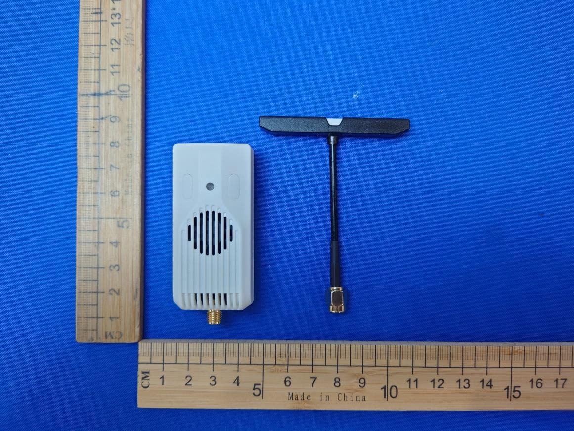
2AT6X-NANOTXV2
Jul 30, 2024Nano TX V2 Module
Equipment Class
DTS - Digital Transmission System
2AT6X-LITERADIO3C
Jan 04, 2024LiteRadio 3 Radio Transmitter
Equipment Class
DSS - Part 15 Spread Spectrum Transmitter
2AT6X-CETUSPRO
Jun 05, 2021Beta Cetus Pro
Equipment Class
DXX - Part 15 Low Power Communication Device Transmitter