2AT7Y-WGFFDashcam
T&F Global Co., Ltd.
Click to zoom
Application Details
- Equipment Class
- DTS - Digital Transmission System
- Date of Grant
- Apr 06, 2022
- Application Purpose
- Original Equipment
- Date of Application
- Apr 06, 2022
- Equipment Note
- Dashcam
- Frequency Range
- 2412.00000000 - 2462.00000000
- Company
- T&F Global Co., Ltd.
- Country
- South Korea
Documents & Files
Document Text
Text extracted from the exhibit documents filed with the FCC. Open a document above to read the original.
Users Manual
FCC StatementProduct information Full HD(FHD) Dashcam Front & Rear Wi-Fi - Front : Full HD 1920 X 1080p 30 frame - Rear : Full HD 1920 X 1080p 30 frame - (Front & Rear) Video check to see in real time - Store and change the settings - Lane departure warning system(LDWS) - Forward collision warning system(FCWS) - Front vehicle start alarm(FVSA) - GPS embedded offers navigation information support such as Time / Location / Speed / Direction. - Provide normal (infinite loop)/ event/ manual recording - Assist voice recording with guidance GPS embedded Advanced Driver Assistance System(ADAS) Various recording Voice recording & guidance Component: Here are components from us. [Option 1][Option 2] Body Normal power cable Cable clip(3EA) Cradle Micro SD card(Adapter) Rear camera / Cable Power cable (Cigar Lighter) Please check to see them carefully as follows. ● Components are subject to change for its feature and quality improvement without further notice. [Guide] FHD Rear camera connection terminalPower connection terminal Front camera Speaker Micro SD card slot Reset hole Mike LED operational status Wi-Fi button Manual recording Volume button Name and feature of each part WFF-800C ItemContent ModelWFF-800C Size (mm) 97(W)mm x 47(H)mm x 33(D)mm SD card capacityMicro SD card 8GB~64GB Recording mode Normal (Infinite loop) Normal (Infinite loop) + Event Parking recording (Front & Rear Motion detection + Event recording) Image sensor Front : Sony sensor IMX307(2M Pixel) Rear : Sony sensor IMX323(2M Pixel) Angle of view Front : 140 。 (D) X 115 。 (H) X 60 。 (V) Rear : 127 。 (D) X 103 。 (H) X 54 。 (V) Resolution Front : Full HD (1920X1080) Rear : Full HD (1920X1080) Frame per second 1CH :Front : 30fps@max(Full HD) 2CH : Front : 30fps@max(Full HD) Rear: 30fps@max(Full HD) Input power12~24V GPSGPS embedded Wi-FiSmartphone playback & setting Operating temperature / Storage temperature -10°C ~ +60°C / -20°C ~ +70°C SD card formatSupport for SD card format on device Backup powerSuper cap embedded Firmware update Support for SD card update Cut off low voltage on parking mode Support from power cable for additional accessories Voice guidance CaseComment Normal (Infinite loop) recording Start constant recording. Event recording Start event recording. Manual recordingStart manual recording. SD card formatFormat SD card. Without SD cardInsert SD card. SD card errorSD card error. GPS connection GPS connected. LED description LEDColorLED displayStatus REC GreenFlicker slowlyNormal (Infinite loop) recording GreenFlicker fast Manual/ Event/ Motion recording RedOnETC (Format, Error, End) GPS GreenOn GPS connection RedOnETC (Format, Error, Disconnection) 2CH GreenOn Rear camera connection OFFOff Rear camera disconnection RedOnETC (Format, Error) Wi-Fi GreenOn Wi-Fi connection RedOnETC (Format, Error, FW update) GreenFlicker slowly Wi-Fi connection, but not connected to smartphone File type 1. Example(File name) 2. Category File nameYear / Month / Date Hour/ Minute / Second File No.Front/ Rear index Micro SD card folder Folder nameDescription INFINITE (Normal recording) - Normal (Infinite loop) recording files are created and stored in the [INFINITE] folder every one minute. - If memory storage is full (70%), the file is deleted from the first recorded file and it continues to loop recording. EVENT (Event / Manual recording) - It stores the recording files in the [EVENT] folder for the total of 20seconds (5seconds before event + 15seconds after event). - If memory storage is full (20%), the file is deleted from the first recorded file. CAPTURE (Photo) - It stores the photo files in the [CAPTURE] folder. - If memory storage is full(5%), the file is deleted from the first recorded file. [INFINITE][EVENT][CAPTURE] - The recording file is created on [INFINITE], [EVENT] folder in micro SD card automatically after filming. NNF_20200131_031739_000001_2.AVI NNF: Normal (Infinite loop) recording NEF: Event/ Manual recording Button Wi-Fi ON / OFF Press button shortly. It can set Wi-Fi ON/ OFF. Volume Press button shortly to adjust volume. (3 -> mute -> 1 -> 2 -> 3) Manual recording Press button shortly for manual recording. A B C Product information FCC Statement Voice guidance Component LED behavior Name and feature of each part Folder and file Button Specification 01 06 02 07 03 08 0405 09 WFF-800C Manual This product is a safe driving assistance product by recording vehicle-driving videos for the purpose of arousing driver's attention, preventing traffic accidents, and providing evidential data to circumstances in case of traffic accidents. This device complies with part 15 of the FCC Rules. Operation is subject to the following two conditions : (1) This device may not cause harmful interference, and (2) this device must accept any interference received, including interference that may cause undesired operation. This equipment has been tested and found to comply with the limits for a Class B digital device, pursuant to part 15 of the FCC Rules. These limits are designed to provide reasonable protection against harmful interference in a residential installation. This equipment generates, uses and can radiate radio frequency energy and, if not installed and used in accordance with the instructions, may cause harmful interference to radio communications. However, there is no guarantee that interference will not occur in a particular installation. If this equipment does cause harmful interference to radio or television reception, which can be determined by turning the equipment off and on, the user is encouraged to try to correct the interference by one or more of the following measures : ▶ Reorient or relocate the receiving antenna. ▶ Increase the separation between the equipment and receiver. ▶ Connect the equipment into an outlet on a circuit different from that to which the receiver is connected. ▶ Consult the dealer or an experienced radio/TV technician for help. This device should be installed and operated with minimum 20…
Text truncated - open the document above for the full version.
Cover Letter(s)
T&F Global Co., Ltd. 654, Samnam-ro, Jinwi-myeon, Pyeongtaek-si, Gyeonggi-do South Korea Date: 04/05/2022 Federal Communications Commission Authorization and Evaluation Division 1435 Oakland Mills Road Columbia, MD 21046 Letter of Authorization We, the undersigned, hereby authorize Geunki Son of DT&C C o., Ltd. to act on our behalf in all manners relating to application for equipment authorization for FCC ID: 2AT7Y-WGFF including signing of all documents relating to these matters. Any and all acts carried out by Geunki Son of DT&C C o., Ltd. on our behalf shall have the same affect as acts of our own. This authorization is valid until further written notice from T&F Global Co., Ltd.. “I, the undersigned, hereby certify that we are not subject to a denial of federal benefits, that includes FCC benefits, pursuant to Section 5301 of the Anti-Drug Abuse Act of 1988, 21 U.S.C. 853(a).” Sincerely, Contact Name: Jinsaeng Park Title: Manager
Cover Letter(s)
T&F Global Co., Ltd. 654, Samnam-ro, Jinwi-myeon, Pyeongtaek-si, Gyeonggi-do South Korea Date: 04/05/2022 Federal Communications Commission Authorization and Evaluation Division 1435 Oakland Mills Road Columbia, MD 21046 Request of Confidentiality FCC ID: 2AT7Y-WGFF To Whom It may Concern: Pursuant to Sections 0.457 and 0.459 of the Commission`s Rules(CFR 47), and Section 552 (b) (4) of the Freedom of Information Act, T&F Global Co., Ltd.. hereby requests confidentiality and treatment of certain information accompanying this application. The materials contain trade secrets and proprietary information not customarily released to the public. The public disclosure of these matters might be harmful to the Applicant and provide unjustified benefits to its competitors. We are also hereby request Short-Term Confidentiality for 180 days after the grant as outlined in Public Notice DA 04-1705. This provision will give T&F Global Co., Ltd.. temporary confidentiality of commercially sensitive information prior to product release. The requested permanent and Short-Term Confidential exhibits are listed as follows: PERMANENT & SHORT-TERM CONFIDENTIAL LIST Exhibit Description PERMANENT 1 Block Diagram 2 Schematics 3 Part Lists 4 Operation Description SHORT-TERM 5 Internal Photos 6 External Photos 7 Test-Setup Photos 8 User Manual The Applicant understands that pursuant to Rule 0.457, disclosure of this application and all accompanying documentations, where applicable, will not be public before the date of the Grant for this application. Sincerely, Contact Name: Jinsaeng Park Title: Manager
External Photos
FCC ID: 2AT7Y-WGFF Copyright Ⓒ 2022, DT&C Co., Ltd. View 1 FCC ID: 2AT7Y-WGFF Copyright Ⓒ 2022, DT&C Co., Ltd. View 2 FCC ID: 2AT7Y-WGFF Copyright Ⓒ 2022, DT&C Co., Ltd. View 3 FCC ID: 2AT7Y-WGFF Copyright Ⓒ 2022, DT&C Co., Ltd. View 4 <SD card slot> FCC ID: 2AT7Y-WGFF Copyright Ⓒ 2022, DT&C Co., Ltd. View 5 <Port>
ID Label/Location Info
R0.5mm 1:1 Size <location> <Zoom in> material : pet label size : 36(W)mm x 6(H)mm R.0.5mm <attached state>
Internal Photos
FCC ID: 2AT7Y-WGFF Copyright Ⓒ 2022, DT&C Co., Ltd. View 1 FCC ID: 2AT7Y-WGFF Copyright Ⓒ 2022, DT&C Co., Ltd. View 2 FCC ID: 2AT7Y-WGFF Copyright Ⓒ 2022, DT&C Co., Ltd. View 3 FCC ID: 2AT7Y-WGFF Copyright Ⓒ 2022, DT&C Co., Ltd. View 4 FCC ID: 2AT7Y-WGFF Copyright Ⓒ 2022, DT&C Co., Ltd. View 5 <Antenna> FCC ID: 2AT7Y-WGFF Copyright Ⓒ 2022, DT&C Co., Ltd. View 6 <GPS Module> <GPS Module> FCC ID: 2AT7Y-WGFF Copyright Ⓒ 2022, DT&C Co., Ltd. View 7 <Wifi Module>
RF Exposure Info
FCC ID: RF feature(Mode) Max Target Power (dBm) ANT Gain (dBi) Maximum EIRP (dBm) Maximum EIRP (mW) Maximum power density (mW/cm 2 ) Requirement (mW/cm 2 ) 802.11b 2 412.00 ~ 2 462.00 3.50 5.06 8.56 7.178 0.001 5 1.000 0 802.11g 2 412.00 ~ 2 462.00 -1.00 5.06 4.06 2.547 0.000 6 1.000 0 802.11n(HT20) 2 412.00 ~ 2 462.00 -1.00 5.06 4.06 2.547 0.000 6 1.000 0 ~~~~~ ▪ S = - Note = / ( 4 X 20 2 X π ) = mW/cm 2 Electric Field strength (V/m) Magnetic field strength (A/m) Power Density (mW/cm 2 ) Averaging time (minutes) 0.3 ~ 1.34 614 1.63 *100 30 1.34 ~ 30 824/f 2.19 / f *180 / f 2 30 30 ~ 300 27.5 0.073 0.2 30 300 ~ 1,500 f / 1500 30 1,500 ~ 100,000 1.0 30 Conclusion : R= Distance to the center of t he radiation of the antenna(20cm) 2AT7Y-WGFF MPE Calculation Frequency range (MHz) Note: Please refer to the operat ion description for Max tune-up power. The EUT will only be used with a separation of 20 centimeters o r greater between the ant enna and the body o f the user. The MPE sample calculation for this exposure is shown below. ▪ Limits for Maximum Permissible Exposure (MPE) Frequency range (MHz) The exposure condition of this device is compliant with FCC EIRP / ( 4 R 2 π ) 7.178 S= Maximum power density(mW/cm 2 ) 0.002 EIRP= Equivalent Isotropic Radiated Power(mW)
Test Report
Report No.: DRTFCC2204-0081 FCC ID: 2AT7Y-WGFF This test report is prohibited to copy or reissue in whole or in part without the approval of DT&C Co., Ltd. TRF-RF-232(04)210316 Pages: 2 / 110 Test Report Version Test Report No. Date Description Revised by Reviewed by DRTFCC2204-0081 Apr, 06. 2022 Initial issue ChangWon Lee JaeJin Lee Report No.: DRTFCC2204-0081 FCC ID: 2AT7Y-WGFF This test report is prohibited to copy or reissue in whole or in part without the approval of DT&C Co., Ltd. TRF-RF-232(04)210316 Pages: 3 / 110 Table of Contents 1. General Information .................................................................................... 4 1.1. Description of EUT .......................................................................................................... 4 1.2. Declaration by the applicant / manufacturer ................................................................ 4 1.3. Testing Laboratory .......................................................................................................... 5 1.4. Testing Environment ....................................................................................................... 5 1.5. Measurement Uncertainty............................................................................................... 5 1.6. Test Equipment List ........................................................................................................ 6 2. Test Methodology ........................................................................................ 7 2.1. EUT Configuration ........................................................................................................... 7 2.2. EUT Exercise .................................................................................................................... 7 2.3. General Test Procedures ................................................................................................ 7 2.4. Instrument Calibration .................................................................................................... 7 2.5. Description of Test Modes.............................................................................................. 8 3. Antenna Requirements ............................................................................... 9 4. Summary of Test Result ........................................................................... 10 5. Test Result ................................................................................................. 11 5.1. Maximum Peak Conducted Output Power .................................................................. 11 5.1.1. Test Setup .................................................................................................................. 11 5.1.2. Test Procedures ........................................................................................................ 11 5.1.3. Test Results ............................................................................................................... 11 5.2. 6 dB Bandwidth ............................................................................................................. 14 5.2.1. Test Setup .................................................................................................................. 14 5.2.2. Test Procedures ........................................................................................................ 14 5.2.3. Test Results ............................................................................................................... 14 5.3. Power Spectral Density ................................................................................................. 27 5.3.1. Test Setup .................................................................................................................. 27 5.3.2. Test Procedures ........................................................................................................ 27 5.3.3. Test Results ............................................................................................................... 27 5.4. Unwanted Emissions (Conducted) .............................................................................. 40 5.4.1. Test Setup .................................................................................................................. 40 5.4.2. Test Procedures ........................................................................................................ 40 5.4.3. Test Results ............................................................................................................... 41 5.5. Unwanted Emissions (Radiated) .................................................................................. 89 5.5.1. Test Setup .................................................................................................................. 91 5.5.2. Test Procedures ........................................................................................................ 91 5.5.3. Test Results ............................................................................................................... 92 5.6. AC Power-Line Conducted Emissions ........................................................................ 96 5.6.1. Test Setup .................................................................................................................. 96 5.6.2. Test Procedures ........................................................................................................ 96 5.6.3. Test Results ............................................................................................................... 96 APPENDIX I .................................................................................................... 97 APPENDIX II ................................................................................................... 98 APPENDIX III ................................................................................................ …
Text truncated - open the document above for the full version.
Test Report
Report No.: DRTFCC2204-0081 FCC ID: 2AT7Y-WGFF This test report is prohibited to copy or reissue in whole or in part without the approval of DT&C Co., Ltd. TRF-RF-232(04)210316 Pages: 89 / 110 5.5. Unwanted Emissions (Radiated) ▣ Test Requirements and limit, Part 15.247(d), Part 15.205, Part 15.209 In any 100 kHz bandwidth outside the frequency band in which the spread spectrum or digitally modulated intentional radiator is operating, the radio frequency power that is produced by the intentional radiator shall be at least 20 dB below that in the 100 kHz bandwidth within the band that contains the highest level of the desired power, based on either an RF conducted or a radiated measurement, provided the transmitter demonstrates compliance with the peak conducted power limits. If the transmitter complies with the conducted power limits based on the use of RMS averaging over a time interval, as permitted under paragraph (b)(3) of Part 15.247 the attenuation required under this paragraph shall be 30 dB instead of 20 dB. Attenuation below the general limits specified in §15.209(a) is not required. In addition, radiated emissions which fall in the restricted bands, as defined in §15.205(a), must also comply with the radiated emission limits specified in §15.209(a) (see §15.205(c)). - Part 15.209: General requirement Frequency (MHz) FCC Limit (uV/m) Measurement Distance (m) 0.009 – 0.490 2 400 / F (kHz) 300 0.490 – 1.705 24 000 / F (kHz) 30 1.705 – 30.0 30 30 Frequency (MHz) FCC Limit (uV/m) Measurement Distance (m) 30 ~ 88 100 ** 3 88 ~ 216 150 ** 3 216 ~ 960 200 ** 3 Above 960 500 3 **Except as provided in paragraph (g), fundamental emissions from intentional radiators operating under this section shall not be located in the frequency bands 54-72 MHz, 76-88 MHz, 174-216 MHz or 470-806 MHz. However, operation within these frequency bands is permitted under other sections of this part, e.g., §§15.231 and 15.241. Report No.: DRTFCC2204-0081 FCC ID: 2AT7Y-WGFF This test report is prohibited to copy or reissue in whole or in part without the approval of DT&C Co., Ltd. TRF-RF-232(04)210316 Pages: 90 / 110 - Part 15.205(a): Restricted band of operation MHz MHz MHz MHz GHz GHz 0.009 ~ 0.110 0.495 ~ 0.505 2.173 5 ~ 2.190 5 4.125 ~ 4.128 4.177 25 ~ 4.177 75 4.207 25 ~ 4.207 75 6.215 ~ 6.218 6.267 75 ~ 6.268 25 6.311 75 ~ 6.312 25 8.291 ~ 8.294 8.362 ~ 8.366 8.376 25 ~ 8.386 75 8.414 25 ~ 8.414 75 12.29 ~ 12.293 12.519 75 ~ 12.520 25 12.576 75 ~ 12.577 25 13.36 ~ 13.41 16.42 ~ 16.423 16.694 75 ~ 16.695 25 16.804 25 ~ 16.804 75 25.5 ~ 25.67 37.5 ~ 38.25 73 ~ 74.6 74.8 ~ 75.2 108 ~ 121.94 123 ~ 138 149.9 ~ 150.05 156.524 75 ~ 156.525 25 156.7 ~ 156.9 162.012 5 ~ 167.17 167.72 ~ 173.2 240 ~ 285 322 ~ 335.4 399.90 ~ 410 608 ~ 614 960 ~ 1 240 1 300 ~ 1 427 1 435 ~ 1 626.5 1 645.5 ~ 1 646.5 1 660 ~ 1 710 1 718.8 ~ 1 722.2 2 200 ~ 2 300 2 310 ~ 2 390 2 483.5 ~ 2 500 2 655 ~ 2 900 3 260 ~ 3 267 3 332 ~ 3 339 3 345.8 ~ 3 358 3 600 ~ 4 400 4.5 ~ 5.15 5.35 ~ 5.46 7.25 ~ 7.75 8.025 ~ 8.5 9.0 ~ 9.2 9.3 ~ 9.5 10.6 ~ 12.7 13.25 ~ 13.4 14.47 ~ 14.5 15.35 ~ 16.2 17.7 ~ 21.4 22.01 ~ 23.12 23.6 ~ 24.0 31.2 ~ 31.8 36.43 ~ 36.5 Above 38.6 Report No.: DRTFCC2204-0081 FCC ID: 2AT7Y-WGFF This test report is prohibited to copy or reissue in whole or in part without the approval of DT&C Co., Ltd. TRF-RF-232(04)210316 Pages: 91 / 110 5.5.1. Test Setup Refer to the APPENDIX I. 5.5.2. Test Procedures 1. The EUT is placed on a non-conductive table. For emission measurements at or below 1 GHz, the table height is 80 cm. For emission measurements above 1 GHz, the table height is 1.5 m. 2. The turntable shall be rotated for 360 degrees to determine the position of maximum emission level. 3. EUT is set 3 m away from the receiving antenna, which is varied from 1 m to 4 m to find out the highest emissions. 4. Maximum procedure was performed on the six highest emissions to ensure EUT compliance. 5. And also, each emission was to be maximized by changing the polarization of receiving antenna both horizontal and vertical. 6. Repeat above procedures until the measurements for all frequencies are complete. Note: Measurement Instrument Setting for Radiated Emission Measurements. - KDB558074 D01v05r02 - Section 8.6 - ANSI C63.10-2013 – Section 11.12 1. Frequency Range Below 1 GHz RBW = 100 or 120 kHz, VBW = 3 x RBW, Detector = Peak or Quasi Peak 2. Frequency Range > 1 GHz Peak Measurement > 1 GHz RBW = 1 MHz, VBW = 3 MHz, Detector = Peak, Sweep time = Auto, Trace mode = Max Hold until the trace stabilizes Average Measurement > 1 GHz 1. RBW = 1 MHz. 2. VBW ≥ 1 / T. 3. Video bandwidth mode or display mode: 1) The instrument shall be set to ensure that video filtering is applied in the power domain. Typically, this requires setting the detector mode to RMS (power averaging) and setting the average-VBW type to power (rms). 2) As an alternative, the instrument may be set to linear detector mode. Ensure that video filtering is applied in linear voltage domain (rather than in a log or dB domain). Some instruments require linear display mode to accomplish this. Others have a setting for average-VBW type, which can be set to “voltage” regardless of the display mode. 4. Detector = peak. 5. Sweep time = auto. 6. Trace mode = max hold. 7. Allow max hold to run for at least [50 × (1 / D)] traces. Duty Cycle Test Mode Date rate T on (ms) T on+off (ms) D = T on / (T on+off ) 1/T (kHz) TM 1 1 Mbps 12.420 19.550 0.635 3 0.081 TM 2 6 Mbps 2.060 18.950 0.108 7 0.485 TM 3 MCS 0 1.920 18.780 0.102 2 0.521 Note1: Where, T= Transmission duration / D= Duty cycle Note2: Please refer to the appendix II for duty cycle plots. Report No.: DRTFCC2204-0081 FCC ID: 2AT7Y-WGFF This test report is prohibited to copy or reissue in whole or in part without the approval of DT&C Co., Ltd. TRF-RF-232(04)210316 Pages: 92 / 110 5.5.3. Test Results - Test Notes 1. The radiated emissions were investigated 9 kHz to 1 GHz and the worst case data was reported. 2. Information of Distance Cor…
Text truncated - open the document above for the full version.
Test Setup Photos
FCC ID: 2AT7Y-WGFF Copyright Ⓒ 2022, DT&C Co., Ltd. Test Setup photographs EUT Position: X-axis EUT Position: Y-axis EUT Position: Z-axis FCC ID: 2AT7Y-WGFF Copyright Ⓒ 2022, DT&C Co., Ltd. Test Setup Photo of Radiated Measurement (0.009 ~ 30MHz) FCC ID: 2AT7Y-WGFF Copyright Ⓒ 2022, DT&C Co., Ltd. Test Setup Photo of Radiated Measurement (Below 1GHz) FCC ID: 2AT7Y-WGFF Copyright Ⓒ 2022, DT&C Co., Ltd. Test Setup Photo of Radiated Measurement (Above 1GHz)
Contact Information
Applicant
Jinsaeng Park(Manager)
Test Firm
Dt&C Co., Ltd.Lee Sang-Wook
Technical Specifications
| # | Rule Parts | Frequency Range | Power Output |
|---|---|---|---|
| 1 | 15C | 2.41 GHz - 2.46 GHz | 7.00 mW |
Other Applications from T&F Global Co., Ltd.
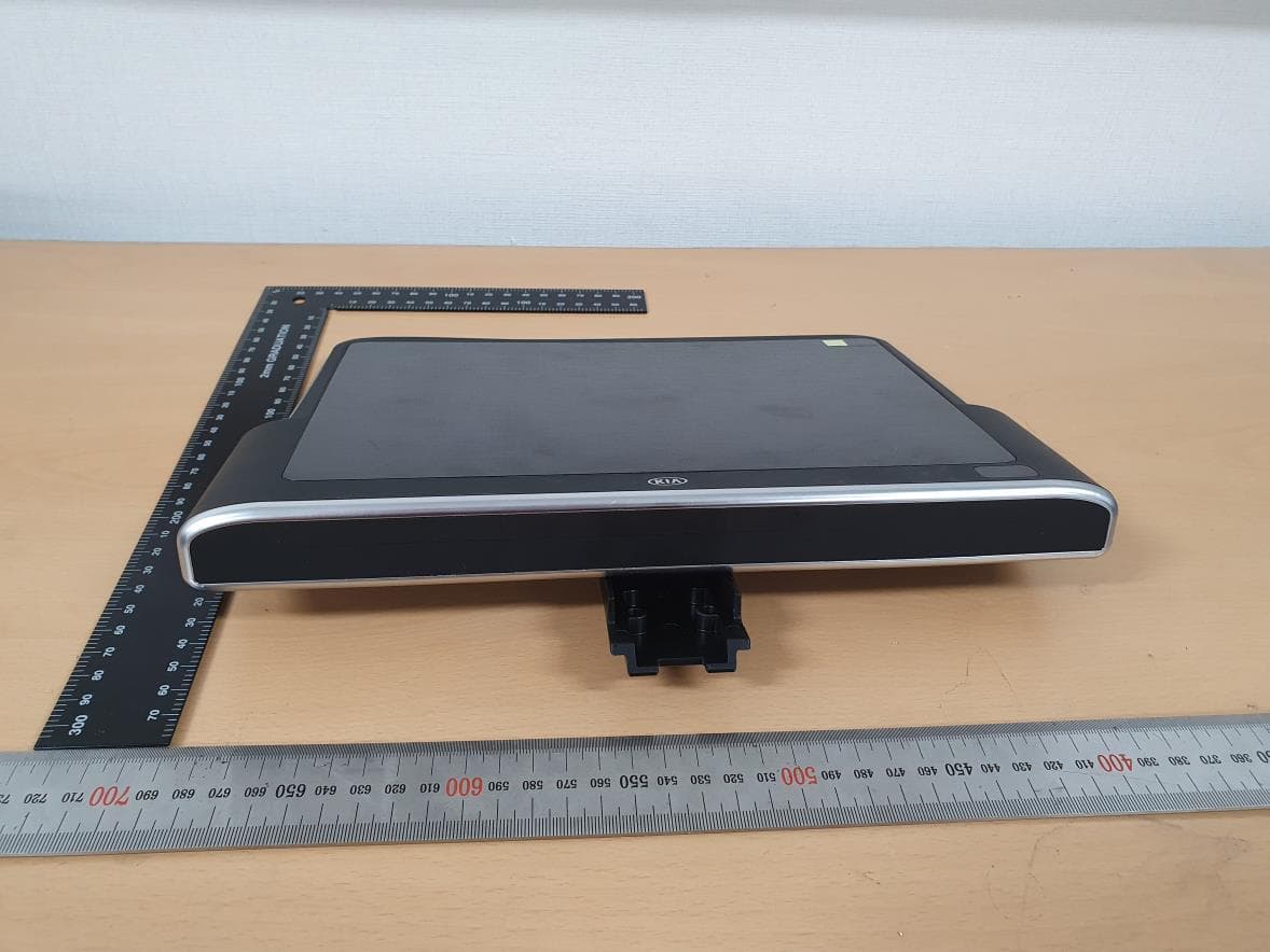
2AT7Y-RSE
Jun 01, 2020Rear Seat Entertainment
Equipment Class
NII - Unlicensed National Information Infrastructure TX