2AT86BT832XBluetooth Low Energy (BLE) Module
SecuRam Systems, Inc.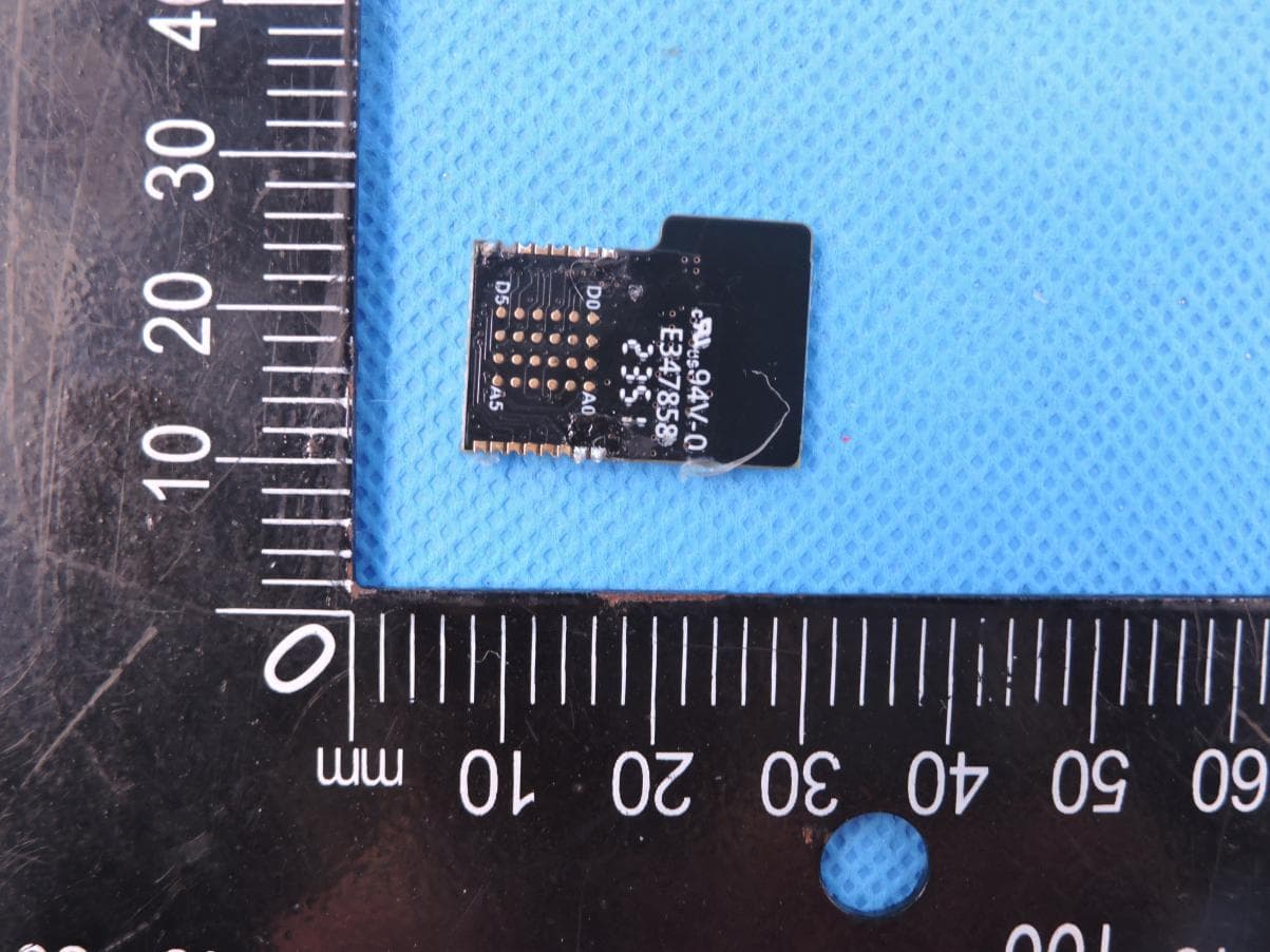
Click to zoom
Application Details
- Equipment Class
- DTS - Digital Transmission System
- Date of Grant
- Sep 17, 2024
- Application Purpose
- Original Equipment
- Date of Application
- Sep 17, 2024
- Equipment Note
- Bluetooth Low Energy (BLE) Module
- Frequency Range
- 2402.00000000 - 2480.00000000
- Company
- SecuRam Systems, Inc.
- Country
- United States
Documents & Files
Document Text
Text extracted from the exhibit documents filed with the FCC. Open a document above to read the original.
Users Manual
1 User Manual 1. 模块Module 蓝牙模块正面 Bluetooth Module, Front 蓝牙模块背面 Bluetooth Module, Back 2. 天线 使用PCB天线 Using PCB antenna 使用PCB天线时,模块上R1焊接,R2不焊接。不需要额外器件。 Weld R1 when using PCB antenna. 2 3. 接口说明 Ports Instructions Port Function Direction Notes / VCC / Typically 3.3V, Vmax=3.6V / GND / Grounded P27 UART_RX I Module serial port receiver, input pull-up P26 UART_TX O Module serial port transmitter, input pull-up DIO I Flash CLK I Flash 3 4. 最小系统原理图 System principle diagram, minimum Notes: 1)模块应使用2.7V-3.3V供电,不应该超出最大供电电压。 Power input range is 2.7V to 3.3V. The maximum supply voltage should not be exceeded. 2)模块通过串口与外部设备进行通信。 Module communicates with external through serial ports 串口配置:Serial port specifications: 波特率Baud rate 115200 数据位Data bits:8bits 停止位Stop bit:1 奇偶校验Parity check:No 3)控制端MCU与模块通信如下图 Communication between MCU control end and BLE module 4 5. 接口说明 Interface 在命令模式下,MCU 发出命令,模块收到命令后,就会立即解析该命令,并给出相应 的响应帧,从发出命令到收到相应需要一定的时间。命令的响应时间不会超过 20ms,典型 值在 8-10ms 之间,在模块有其他更高级的任务处理的时候,响应时间会变长一些,但不 会超过 20ms。 MCU 要将数据发送出去时,需要遵循一定的时序,低功耗蓝牙的通信速率是有限的, 为了防止拥塞造成的大量丢包,MCU 向模块写入 数据的速率不能太快。每包数据需要间隔20ms。 In command mode, MCU will send commands, and after the module received a command, the module will immediately parse the command and give the corresponding response frame. It takes a certain time from issuing the command to receiving the corresponding frame. The response time of the command will not exceed 20ms, typical values are between 8-10ms, and the response time will be longer when the module has other more advanced tasks to process, but will not exceed 20ms. When MCU needs to send data out, it needs to follow a certain time sequence. The communication rate of low power consumption Bluetooth is limited. In order to prevent packet loss caused by congestion, the MCU cannot write data to the module at an extremely fast rate. The interval for each data packet should be at least 20ms. 1)串口数据帧结构 Serial data frame structure 透传模块的命令有一定的格式,包含“字头”、“命令 ID”、“命令信息长度”、“命令信息” 五个区域。Commands from transparent transmission module have certain format. The 5 command should contain five parts, which are prefix (2 parts), command ID, command length and command data. 2) 串口命令Serial port command 发送 Send command 字头Prefix I 01 1 byte 字头Prefix II FC 1 byte 命令 ID Command ID CMD 1 byte 信息长度 Command length LEN 1 byte 信息内容 Command data DATA N byte (N<255) 应答 Answer command 字头Prefix I 04 1 byte 字头Prefix II FC 1 byte 命令 ID Command ID CMD 1 byte 信息长度 Command length LEN 1 byte 信息内容 Command data DATA N byte (N<255) 3)串口命令Serial port command 0x07 查询MAC地址 Querying MAC Addresses 0x12 设置广播 Set broadcast 0x25 连接到指定设备 Connect to the specified device 0x2A 已连接Connected 0x41 发送数据 Send data 6 0x42 收到数据 Receive data 0x43 断开连接 Disconnect 0x48 睡眠 Sleep 4) 常用指令说明 Frequently used commands 命令字 命令描述 示例 07 MAC 地址查询 格式:01 FC 07 00 返回:命令正确 04 FC 07 06 xx...(共 6 个字节,低字节 序) 命令错误 04 FC 02 00 12 广播数据设置 格式:01 FC 12 xx(广播数据长度)xx...(广播数据) 广播数据长度取值范围是 1-29,必须与后面广播数据字节 数相符 上电默认:空 返回:命令正确 04 FC 01 00 命令错误 04 FC 02 00 41 发送数据(透传) 格式:01 FC 41 xx (数据长度) xx...(用户数据) 数据长度取值范围是 1-80,用户数据字节数必须和数据长 度相符 返回:能正常发送 04 FC 01 00 不能正常发送 04 FC 02 00 42 接收数据(透传) MCU 向模块发送该命令无效,当模块收到数据,并且模块 处于命令模式时,模块主动向 MCU 发送该命令的响应, 响应的格式如下: 04 FC 42 xx(数据长度) xx...(用户数据) 数据长度的范围是 1-20,后面紧跟用户数据 7 Command Description Example 07 Querying MAC Addresses Format: 01 FC 07 00 Return: Correct command should be 04 FC 07 06 xx... (Total 6 bytes, low byte order) Incorrect command should be 04 FC 02 00 12 Set broadcast Format: 01 FC 12 xx (broadcast data length) xx... (Broadcast data) The broadcast data length ranges from 1 to 29 bytes and must be consistent with the number of broadcast data bytes Power-on Default: None Correct command should be 04 FC 01 00 Incorrect command should be 04 FC 02 00 41 Send data (Not encrypted) Format: 01 FC 41 xx (Data length) xx... (User data) The data length ranges from 1 to 80. The number of data bytes must be consistent with the data length Correct command should be 04 FC 01 00 Incorrect command should be 04 FC 02 00 42 Receive data (Not encrypted) It is invalid for MCU to send the command to the module. When the module receives data and is in command mode, the module actively sends the response of the command to the MCU in the following format: 04 FC 42 xx(Data length) xx... (User data) Data length ranges from 1 to 20, followed by user data 8 FCC Statement This device complies with part 15 of the FCC Rules. Operation is subject to the following two conditions: (1) This device may not cause harmful interference, and (2) this device must accept any interference received, including interference that may cause undesired operation. Any Changes or modifications not expressly approved by the party responsible for compliance could void the user's authority to operate the equipment. The modular can be installed or integrated in mobile or fix devices only. This modular cannot be installed in any portable device. FCC Radiation Exposure Statement This modular complies with FCC RF radiation exposure limits set forth for an uncontrolled environment. This transmitter must not be co-located or operating in conjunction with any other antenna or transmitter. This modular must be installed and operated with a minimum distance of 20 cm between the radiator and user body. If the FCC identification number is not visible when the module is installed inside another device, then the outside of the device into which the module is installed must also display a label referring to the enclosed module. This exterior label can use wording such as the following: “Contains Transmitter Module FCC ID: 2AT86BT832X Or Contains FCC ID: 2AT86BT832X” When the module is installed inside another device, the user manual of the host must contain below warning statements; 1. This device complies with Part 15 of the FCC Rules. Operation is subject to the following two conditions: (1) This device may not cause harmful interference. (2) This device must accept any interference received, including interference that may…
Text truncated - open the document above for the full version.
Attestation Statements
SECURAM Systems, Inc. 2024-09-02 Eurofins Electrical and Electronic Testing NA, Inc. 914 West Patapsco Avenue Baltimore, MD 21230 RE: Attestation Statements Part 2.911(d)(5)(i) request for (FCC ID: 2AT86BT832X) [SECURAM Systems, Inc.] (“the applicant”) certifies that the equipment for which authorization is sought is not “covered” equipment prohibited from receiving an equipment authorization pursuant to section 2.903 of the FCC rules. Sincerely, Jiankuai Li SECURAM Systems, Inc. 2024-09-02 Eurofins Electrical and Electronic Testing NA, Inc. 914 West Patapsco Avenue Baltimore, MD 21230 RE: Attestation Statements Part 2.911(d)(5)(ii) request for (FCC ID: 2AT86BT832X) [SECURAM Systems, Inc.] (“the applicant”) certifies that, as of the date of the filing of the application, the applicant is not identified on the Covered List as an entity producing “covered” equipment. Sincerely, Jiankuai Li
Cover Letter(s)
THIS MUST BE SIGNED BY THE APPLICANT/AGENT AND SHOULD BE PLACED ON APPROPRIATE LETTERHEAD Request for Modular/Limited Modular Approval Date: September 13, 2024 Subject: Manufacturer’s Declaration for ☒ - Modular Approval ☐ - Split Modular Approval ☐ - Limited Modular Approval ☐ - Limited Split Modular Approval Confidentiality Request for: FCC ID: 2AT86BT832X 8 Basic Requirements – FCC Part 15.212(a)(1) For Items Marked “NO(*)”, the Limited Module Description Must be Filled Out on the Following Pages Modular Approval Requirement Requirement Met 1. The modular transmitter must have its own RF shielding. This is intended to ensure that the module does not have to rely upon the shielding provided by the device into which it is installed in order for all modular transmitter emissions to comply with FCC limits. It is also intended to prevent coupling between the RF circuitry of the module and any wires or circuits in the device into which the module is installed. Such coupling may result in non-compliant operation. The physical crystal and tuning capacitors may be located external to the shielded radio elements. 15.212(a)(1)(i) ☒ - YES ☐ - NO(*) Details: Yes, with shielded 2. The modular transmitter must have buffered modulation/data inputs (if such inputs are provided) to ensure that the module will comply with FCC requirements under conditions of excessive data rates or over-modulation. 15.212(a)(1)(ii) ☒ - YES ☐ - NO(*) Details: Yes , All inputs to the modules are buffered through logic or microprocessor inputs. 3. The modular transmitter must have its own power supply regulation on the module. This is intended to ensure that the module will comply with FCC requirements regardless of the design of the power supplying circuitry in the device into which the module is installed. 15.212(a)(1)(iii) ☒ - YES ☐ - NO(*) Details: YES – The module contains its own power supply regulation. Please refer to schematic filed with this application> 4. The modular transmitter must comply with the antenna and transmission system requirements of §§ 15.203, 15.204(b), 15.204(c), 15.212(a), and 2.929(b). The antenna must either be permanently attached or employ a ‘‘unique’’ antenna coupler (at all connections between the module and the antenna, including the cable). The ‘‘professional installation’’ provision of § 15.203 is not applicable to modules but can apply to limited modular approvals under paragraph 15.212(b). 15.212(a)(1)(iv) ☒ - YES ☐ - NO(*) Details: YES – The module use PCB Antenna 5. The modular transmitter must be tested in a stand-alone configuration, i.e., the module must not be inside another device during testing. This is intended to demonstrate that the module is capable of complying with Part 15 emission limits regardless of the device into which it is eventually installed. Unless the transmitter module will be battery powered, it must comply with the AC line conducted requirements found in Section 15.207. AC or DC power lines and data input/output lines connected to the module must not contain ferrites, unless they will be marketed with the module (see Section 15.27(a)). The length of these lines shall be length typical of actual use or, if that length is unknown, at least 10 centimeters to insure that there is no coupling between the case of the module and supporting equipment. Any accessories, peripherals, or support equipment connected to the module during testing shall be unmodified or commercially available (see Section 15.31(i)). 15.212(a)(1)(v) ☒ - YES ☐ - NO(*) Details: YES – The module was tested stand-alone as shown in test setup photographs filed with this application> THIS MUST BE SIGNED BY THE APPLICANT/AGENT AND SHOULD BE PLACED ON APPROPRIATE LETTERHEAD Modular Approval Requirement Requirement Met 6. The modular transmitter must be labeled with its own FCC ID number, or use an electron display (see KDB Publication 784748). If using a permanently affixed label with its own FCC ID number, if the FCC ID is not visible when the module is installed inside another device, then the outside of the device into which the module is installed must also display a label referring to the enclosed module. This exterior label can use wording such as the following: “Contains Transmitter Module FCC ID: XYZMODEL1” or “Contains FCC ID: XYZMODEL1.” Any similar wording that expresses the same meaning may be used. The Grantee may either provide such a label, an example of which must be included in the application for equipment authorization, or, must provide adequate instructions along with the module which explain this requirement. In the latter case, a copy of these instructions must be included in the application for equipment authorization. If the modular transmitter uses an electronic display of the FCC identification number, the information must be readily accessible and visible on the modular transmitter or on the device in which it is installed. If the module is installed inside another device, then the outside of the device into which the module is installed must display a label referring to the enclosed module. This exterior label can use wording such as the following: “Contains FCC certified transmitter module(s).” Any similar wording that expresses the same meaning may be used. The user manual must include instructions on how to access the electronic display. A copy of these instructions must be included in the application for equipment authorization. 15.212(a)(1)(vi) ☒ - YES ☐ - NO(*) Details: Yes ,The modular has a permanent fixed label, and below statement was listed in the User Manual; The host device must be labeled to display the FCCID of the module Contains FCC ID: 2AT86BT832X 7. The modular transmitter must comply with all specific rule or operating requirements applicable to the transmitter, including all the conditions provided in the integration instructions by the grantee. A copy of these instructions must be included in the application for equipment authorization. For example…
Text truncated - open the document above for the full version.
Cover Letter(s)
SECURAM Systems, Inc. 2024-09-02 Eurofins Electrical and Electronic Testing NA, Inc. 914 West Patapsco Avenue Baltimore, MD 21230 RE: CONFIDENTIALITY REQUEST FOR (Bluetooth Low Energy (BLE) Module / BT832x-Mode-SMD / FCC ID: 2AT86BT832X) To Whom It May Concern: This letter serves as an official request for confidentiality under sections 0.457 and 0.459 of CFR 47. We have requested that the •Schematics •Block diagram •Operation description required to be submitted with this application be permanently withheld from public review. These materials contain trade secrets and proprietary information and are not customarily released to the public. The public disclosure of this information might be harmful to the company and provide unjustified benefits to our competitors. Please contact me if there is any information you may need. Sincerely, Jiankuai Li
Cover Letter(s)
SECURAM Systems, Inc. 2024-09-02 Eurofins Electrical and Electronic Testing NA, Inc. 914 West Patapsco Avenue Baltimore, MD 21230 RE: Short Term Confidentiality Request For(Bluetooth Low Energy (BLE) Module / BT832x-Mode-SMD / FCC ID: 2AT86BT832X) To Whom It May Concern: In accordance with sections 0.457 and 0.459 of CFR 47, < SECURAM Systems, Inc. >. requests short-term Confidentiality of following sections of this application for a period of 180days after grant is issued. Internal photo These documents contain detailed system and equipment descriptions and related information about the product, which < SECURAM Systems, Inc.> considers to be proprietary, confidential, and a custom design and otherwise, would not release to the general public. Since this design is a basis from which future technological products will evolve, < SECURAM Systems, Inc.> feels that this information would be of benefit to its competitors, and that the disclosure of the information in these documents would give our competitors an unfair advantage in the market. Please contact me if there is any information you may need. Sincerely, Jiankuai Li
External Photos
Page 1 of 1 Report No.: STS2408140 APPENDIX-PHOTOGRAPHS OF EUT CONSTRUCTIONAL DETAILS Model: BT832x-Mode-SMD Photo 1 Photo 2 BT Antenna
ID Label/Location Info
Label 1cm*1cm
RF Exposure Info
The test results presented in this report relate only to the object tested. This report shall not be reproduced, except in full, without the written approval of the Shenzhen STS Test Services Co., Ltd. Radio Test Report Report No.: STS2408140H01 Issued for SECURAM Systems, Inc. 3325 Grande Vista Drive Newbury Park, CA 91320 United States Product Name: Bluetooth Low Energy (BLE) Module Brand Name: SECURAM Model Name: BT832x-Mode-SMD Series Model(s): N/A FCC ID: 2AT86BT832X Test Standards: FCC 47CFR §2.1091 Page 2 of 9 Report No.: STS2408140H01 TEST REPORT Applicant’s Name ................. : SECURAM Systems, Inc. Address ................................. : 3325 Grande Vista Drive Newbury Park, CA 91320 United States Manufacturer's Name ........... : Nanjing Easthouse Electrical Co., Ltd. Address ................................. : No. 27 Puzhou Road, Jiangbei New Area, Nanjing, 210032, China Product Description Product Name ........................ : Bluetooth Low Energy (BLE) Module Brand ................................... : SECURAM Model Number ....................... : .. : BT832x-Mode-SMD Series Model(s) ...................... : N/A Standards ............................. : FCC 47CFR §2.1091 447498 D04 Interim General RF Exposure Guidance v01 The test results presented in this report relate only to the object tested. This report shall not be reproduced, except in full, without the written approval of the Shenzhen STS Test Services Co., Ltd. Date of Test ........................................... : Date of receipt of test item ...................... : 27 Aug. 2024 Date (s) of performance of tests ............. : 27 Aug. 2024 ~ 30 Aug. 2024 Date of Issue .......................................... : 30 Aug. 2024 Test Result .............................................. : Pass Testing Engineer : (Aaron Bu) Technical Manager : (Tony Liu) Authorized Signatory : (Bovey Yang) Page 3 of 9 Report No.: STS2408140H01 TABLE OF CONTENTS 1. GENERAL INFORMATION 5 1.1 GENERAL DESCRIPTION OF THE EUT 5 1.2 TEST FACTORY 5 2. FCC 47CFR §2.1091 REQUIREMENT 6 2.1 TEST STANDARDS 6 2.2 LIMIT 6 2.3 TEST RESULT 9 Page 4 of 9 Report No.: STS2408140H01 Revision History Rev. Issue Date Report No. Effect Page Contents 00 30 Aug. 2024 STS2408140W01 ALL Initial Issue Page 5 of 9 Report No.: STS2408140H01 1. GENERAL INFORMATION 1.1 GENERAL DESCRIPTION OF THE EUT Product Name Bluetooth Low Energy (BLE) Module Brand SECURAM Model Number BT832x-Mode-SMD Series Model(s) N/A Model Difference N/A Product Description The EUT is Bluetooth Low Energy (BLE) Module Operation Frequency: 2402~2480 MHz Modulation Type: GFSK Antenna gain: 2dBi Antenna Designation: PCB Antenna Rating Input: C 3.3V Hardware version number V1.2 Software version number V3.0 1.2 TEST FACTORY SHENZHEN STS TEST SERVICES CO., LTD Add. : 101, Building B, Zhuoke Science Park, No.190 Chongqing Road, ZhanChengShequ, Fuhai Sub-District, Bao’an District, Shenzhen, Guang Dong, China FCC test Firm Registration Number: 625569 IC test Firm Registration Number: 12108A A2LA Certificate No.: 4338.01 Page 6 of 9 Report No.: STS2408140H01 2. FCC 47CFR §2.1091 REQUIREMENT 2.1 TEST STANDARDS Follow the maximum permissible exposure (MPE) limits specified in 447498 D04 Interim General Radio Frequency Exposure Guidelines v01. The gain of the antenna used in the product was extracted from the supplied antenna data sheet and the maximum total power input to the antenna was also measured. Calculate the distance from the product to the MPE limit by the formula. 2.2 LIMIT For single RF sources (i.e., any single fixed RF source, mobile device, or portable device, as defined in paragraph (b)(2) of this section): A single RF source is exempt if: (A) The available maximum time-averaged power is no more than 1 mW, regardless of separation distance. This exemption may not be used in conjunction with other exemption criteria other than those in paragraph (b)(3)(ii)(A) of Part 1.1307. Medical implant devices may only use this exemption and that in paragraph (b)(3)(ii)(A); (B) Or the available maximum time-averaged power or effective radiated power (ERP), whichever is greater, is less than or equal to the threshold Pth (mW) described in the following formula. This method shall only be used at separation distances (cm) from 0.5 centimeters to 40 centimeters and at frequencies from 0.3 GHz to 6 GHz (inclusive). Pth is given by: Page 7 of 9 Report No.: STS2408140H01 (C) Or using below table and the minimum separation distance (R in meters) from the body of a nearby person for the frequency (f in MHz) at which the source operates, the ERP (watts) is no more than the calculated value prescribed for that frequency. For the exemption in Table 1 to apply, R must be at least λ/2π, where λ is the free-space operating wavelength in meters. If the ERP of a single RF source is not easily obtained, then the available maximum time-averaged power may be used in lieu of ERP if the physical dimensions of the radiating structure(s) do not exceed the electrical length of λ/4 or if the antenna gain is less than that of a half-wave dipole (1.64 linear value). RF Source frequency (MHz) Threshold ERP(watts) 0.3-1.34 1,920 R 2 . 1.34-30 3,450 R 2 /f 2 . 30-300 3.83 R 2 . 300-1,500 0.0128 R 2 f. 1,500-100,000 19.2R 2 . Page 8 of 9 Report No.: STS2408140H01 For multiple RF sources: Multiple RF sources are exempt if: (A) The available maximum time-averaged power of each source is no more than 1 mW and there is a separation distance of two centimeters between any portion of a radiating structure operating and the nearest portion of any other radiating structure in the same device, except if the sum of multiple sources is less than 1 mW during the time-averaging period, in which case they may be treated as a single source (separation is not required). This exemption may not be used in conjunction with other exemption criteria other than those is paragraph (b)(3)(i)(A) of Part 1.1307. Medical implant devices may only …
Text truncated - open the document above for the full version.
Test Report
Antenna Specification 天线型号Antenna Model Number:ANT1 制造商Manufacturer:Nanjing Easthouse Electrical Co,. Ltd. 天线外观Antenna exterior Figure1 带PCB天线模块如图1。 Module contains PCB antenna ANT1, see Figure 1. ANT1天线参数 Specifications for ANT1. BLE TYPE PARA 射频天线的形式Form of RF antenna PCB Antenna 天线尺寸Measurements 11*7MM 频率范围Frequency range 2440MHz-2480MHz 调制方式Form of Modulation GFSK 发射功耗Transmitted power consumption -40~+4dB 灵敏度Sensitivity -96 电压驻波比Voltage standing wave ratio 2 天线阻抗Antenna impedance 50Ω 极化形式Form of polarization Vertical 传输距离Transmission distance 30 BLE BLE 4.2 ANT1 GAIN GAIN TEST MAX GAIN 2.0dBi GAIN Frequency MHz 2400 2450 2500 GAIN dBi 2.0 1.25 1.55 Figure2 Antenna ANT1, 2400MHz Figure3 Antenna ANT1, 2450MHz Figure4 Antenna ANT1, 2500MHz
Test Report
The test results presented in this report relate only to the object tested. This report shall not be reproduced, except in full, without the written approval of the Shenzhen STS Test Services Co., Ltd. Radio Test Report Report No.:STS2408140W01 Issued for SECURAM Systems, Inc. 3325 Grande Vista Drive Newbury Park, CA 91320 United States Product Name: Bluetooth Low Energy (BLE) Module Brand Name: SECURAM Model Name: BT832x-Mode-SMD Series Model(s): N/A FCC ID: 2AT86BT832X Test Standards: FCC Part15.247 S T L A B S Page 2 of 57 Report No.: STS2408140W01 TEST REPORT Applicant’s Name ................. : SECURAM Systems, Inc. Address ................................. : 3325 Grande Vista Drive Newbury Park, CA 91320 United States Manufacturer's Name .......... : Nanjing Easthouse Electrical Co., Ltd. Address ................................. : No. 27 Puzhou Road, Jiangbei New Area, Nanjing, 210032, China Product Description Product Name ....................... : Bluetooth Low Energy (BLE) Module Brand Name .......................... : SECURAM Model Name .......................... : BT832x-Mode-SMD Series Model(s) .................... : N/A Test Standards ..................... : FCC Part15.247 Test Procedure ...................... : ANSI C63.10-2020 This device described above has been tested by STS, the test results show that the equipment under test (EUT) is in compliance with the FCC requirements. And it is applicable only to the tested sample identified in the report. The test results presented in this report relate only to the object tested. This report shall not be reproduced, except in full, without the written approval of the Shenzhen STS Test Services Co., Ltd. Date of Test ........................................... : Date of receipt of test item ..................... : 27 Aug. 2024 Date (s) of performance of tests ............. : 27 Aug. 2024 ~ 30 Aug. 2024 Date of Issue .......................................... : 30 Aug. 2024 Test Result.............................................. : Pass Testing Engineer : (Aaron Bu) Technical Manager : (Tony Liu) Authorized Signatory : (Bovey Yang) Page 3 of 57 Report No.: STS2408140W01 Table of Contents 1. SUMMARY OF TEST RESULTS 6 1.1 TEST FACTORY 7 1.2 MEASUREMENT UNCERTAINTY 7 2. GENERAL INFORMATION 8 2.1 GENERAL DESCRIPTION OF THE EUT 8 2.2 DESCRIPTION OF THE TEST MODES 10 2.3 TEST SOFTWARE AND POWER LEVEL 10 2.4 BLOCK DIAGRAM SHOWING THE CONFIGURATION OF SYSTEM TESTED 11 2.5 DESCRIPTION OF NECESSARY ACCESSORIES AND SUPPORT UNITS 12 2.6 EQUIPMENTS LIST 13 3. EMC EMISSION TEST 14 3.1 CONDUCTED EMISSION MEASUREMENT 14 3.2 TEST PROCEDURE 15 3.3 TEST SETUP 15 3.4 EUT OPERATING CONDITIONS 15 3.5 TEST RESULTS 16 4. RADIATED EMISSION MEASUREMENT 18 4.1 RADIATED EMISSION LIMITS 18 4.2 TEST PROCEDURE 20 4.3 TEST SETUP 21 4.4 EUT OPERATING CONDITIONS 21 4.5 FIELD STRENGTH CALCULATION 22 4.6 TEST RESULTS 22 5. CONDUCTED SPURIOUS & BAND EDGE EMISSION 29 5.1 LIMIT 29 5.2 TEST PROCEDURE 29 5.3 TEST SETUP 29 5.4 EUT OPERATION CONDITIONS 29 5.5 TEST RESULTS 29 6. POWER SPECTRAL DENSITY TEST 30 6.1 LIMIT 30 6.2 TEST PROCEDURE 30 6.3 TEST SETUP 30 Page 4 of 57 Report No.: STS2408140W01 Table of Contents 6.4 EUT OPERATION CONDITIONS 30 6.5 TEST RESULTS 30 7. BANDWIDTH TEST 31 7.1 LIMIT 31 7.2 TEST PROCEDURE 31 7.3 TEST SETUP 31 7.4 EUT OPERATION CONDITIONS 31 7.5 TEST RESULTS 31 8. PEAK OUTPUT POWER TEST 32 8.1 LIMIT 32 8.2 TEST PROCEDURE 32 8.3 TEST SETUP 33 8.4 EUT OPERATION CONDITIONS 33 8.5 TEST RESULTS 33 9. ANTENNA REQUIREMENT 34 9.1 STANDARD REQUIREMENT 34 9.2 EUT ANTENNA 34 APPENDIX 1-TEST DATA 35 1. DUTY CYCLE 35 2. MAXIMUM AVERAGE CONDUCTED OUTPUT POWER 38 3. MAXIMUM PEAK CONDUCTED OUTPUT POWER 41 4. -6DB BANDWIDTH 44 5. MAXIMUM POWER SPECTRAL DENSITY LEVEL 47 6. BAND EDGE 50 7. CONDUCTED RF SPURIOUS EMISSION 53 APPENDIX 2- EUT TEST PHOTO 57 Page 5 of 57 Report No.: STS2408140W01 Revision History Rev. Issue Date Report No. Effect Page Contents 00 30 Aug. 2024 STS2408140W01 ALL Initial Issue Page 6 of 57 Report No.: STS2408140W01 1. SUMMARY OF TEST RESULTS Test procedures according to the technical standards: KDB 558074 D01 15.247 Meas Guidance v05r02. FCC Part 15.247,Subpart C Standard Section Test Item Judgment Remark 15.207 Conducted Emission PASS -- 15.247 (a)(2) 6dB Bandwidth PASS -- 15.247 (b)(3) Output Power PASS -- 15.209 Radiated Spurious Emission PASS -- 15.247 (d) Conducted Spurious & Band Edge Emission PASS -- 15.247 (e) Power Spectral Density PASS -- 15.205 Restricted bands of operation PASS -- Part 15.247(d)/ Part 15.209(a) Band Edge Emission PASS -- 15.203 Antenna Requirement PASS -- NOTE: (1) ‘N/A’ denotes test is not applicable in this Test Report. (2) All tests are according to ANSI C63.10-20120. Page 7 of 57 Report No.: STS2408140W01 1.1 TEST FACTORY SHENZHEN STS TEST SERVICES CO., LTD Add. : 101, Building B, Zhuoke Science Park, No.190 Chongqing Road, ZhanChengShequ, Fuhai Sub-District, Bao’an District, Shenzhen, Guang Dong, China FCC test Firm Registration Number: 625569 IC test Firm Registration Number: 12108A A2LA Certificate No.: 4338.01 1.2 MEASUREMENT UNCERTAINTY The reported uncertainty of measurement y ± U, where expended uncertainty U is based on a standard uncertainty multiplied by a coverage factor of k=2, providing a level of confidence of approximately 95 %. No. Item Uncertainty 1 RF output power, conducted ±0.755dB 2 Unwanted Emissions, conducted ±2.874dB 3 All emissions, radiated 9K-30MHz ±3.80dB 4 All emissions, radiated 30M-1GHz ±4.18dB 5 All emissions, radiated 1G-6GHz ±4.90dB 6 All emissions, radiated>6G ±5.24dB 7 Conducted Emission (9KHz-150KHz) ±2.19dB 8 Conducted Emission (150KHz-30MHz) ±2.53dB 9 Occupied Channel Bandwidth ±3.5% 10 Power Spectral Density, conducted ±1.245dB 11 Duty Cycle ±3.2% Page 8 of 57 Report No.: STS2408140W01 2. GENERAL INFORMATION 2.1 GENERAL DESCRIPTION OF THE EUT Product Name Bluetooth Low Energy (BLE) Module Brand Name SECURAM Model Name BT832x-Mode-SMD Series Model(s) N/A Model Dif…
Text truncated - open the document above for the full version.
Test Setup Photos
Page 1 of 2 FCC ID: 2AT86BT832X DTS Setup photo Model: BT832x-Mode-SMD DTS radiation L DTS radiation H Page 2 of 2 FCC ID: 2AT86BT832X DTS conduction
Contact Information
Applicant
Shinee Zhang
Technical Contact
Shenzhen STS Test Services Co., Ltd.Bovey Yang
[email protected]075536886288
A 1/F, Building B, Zhuoke Science Park, No.190 Cho · Shenzhen · China
Non-Technical Contact
Shenzhen STS Test Services Co., Ltd.Bovey Yang
[email protected]075536886288
Test Firm
SHENZHEN STS TEST SERVICES CO.,LTD.Bovey Yang
[email protected]+86 755-36886288
Technical Specifications
| # | Rule Parts | Frequency Range | Power Output |
|---|---|---|---|
| 1 | 15C | 2.40 GHz - 2.48 GHz | 230.00 µW |
Other Applications from SecuRam Systems, Inc.

2AT86-SHTB01
Jan 06, 2020SECURAM Touch
Equipment Class
DTS - Digital Transmission System