2AT8M-VW-S1-V2X1BEAM-VW-S1
Ackcio Pte. Ltd.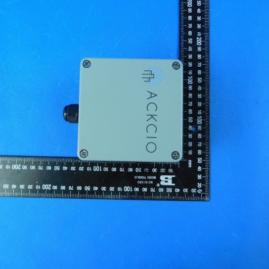
Click to zoom
Application Details
- Equipment Class
- DTS - Digital Transmission System
- Date of Grant
- Mar 18, 2020
- Application Purpose
- Original Equipment
- Date of Application
- Mar 18, 2020
- Equipment Note
- BEAM-VW-S1
- Frequency Range
- 902.50000000 - 927.50000000
- Company
- Ackcio Pte. Ltd.
- Country
- Singapore
Documents & Files
Document Text
Text extracted from the exhibit documents filed with the FCC. Open a document above to read the original.
Users Manual
Setting up Vibrating Wire Node (BEAM-VW-S1) This page provides information on setting up a VibratingWire Node to work with the offline Ackcio Beam gateway. Installation The Nodes can be directly affixed to a flat surface using M4 screws. However, for more sophisticated mounting scenarios, we recommend using the node bracket. The node bracket can be used to easily mount the node on flat surfaces, on pipes using U-bolts or cable-ties, or in other complicated settings. If you are using the bracket, first fix the node device to the bracket using M4 screws and nuts as shown below. Connect the SMA antenna to the bulkhead. Once the mounting is complete, the node should look as follows. Node Setup 1.Connect the node antenna to the antenna bulkhead. 2. Connect the sensor wires to the node while ensuring that the wires are plugged in correctly. S+: Vibrating wire input of sensor S-: Vibrating wire input of sensor T+: Thermistor T- : Thermistor PLS1 : Pulse input one (applicable for switch sensor only) PLS2 : Pulse input two (applicable for switch sensor only) GND : Pulse ground (applicable for switch sensor only) SHLD: Shield wire of sensor 3. Switch off the Node and insert the battery while ensuring the polarity is followed correctly. Configuring via the Ackcio Beam App 1.Download Ackcio Beam app at Google Playstore and connect to Gateway WiFi. 2. Plug in the USB end of the cable via an OTG adapter to your Android phone. 3. Important! Please make sure the Node is switch off before connecting to your Android phone. 4. Plugin micro USB end to the Node. 5. Switch on the Node. 6. Open the Ackcio Beam app on the phone. On toggle button, "Cloud" option is for Ackcio Online Live version. "Gateway" option is for Offline version. Please choose "Gateway" to proceed with offline version. (Please note that you need to add the Node and create the project first before you commission the node. Please refer to Gateway Setup for details.) "Gateway" option to connect to Offline Gateway (i) You will see the project which you have already created once you open your Ackcio app. Click the button to download the project and go in to the project, you will see the project details. (ii) Press "Reset" button on the Node itself. Then click on “Setup Device” on the lower left menu on Ackcio app, the app will show connected node information. If the connection is unsuccessful, press "Reset" button on Node and connect again. (iii) <Optional Step> If Wireless Mesh (Relay) function is to be deployed, click on "Wireless Mesh" toggle button to enable. Once done, click on “Setup Sensor”, you can now configure the sensor settings. (iv) You will see this page with the available channels. Click “Arrow icon” on the respective channel which your sensor is connected to. (v) Sensor Code: Your desired sensor name. Sensor Type: Select respective sensor type. Parameters: Turn on the parameters as connected to the Node. Mode: Please select the respective Sweep Mode (A or B or C), depending on the sensor. (vi) Click Save Settings. The Node will now read the sensor that was just configured. (vii) On next page, you will see the first reading. (viii) To get another reading, click on the arrow icon. If the reading is ok, please enable the sensor using the blue color icon. (ix) Repeat above steps if you wish to change the sensor type. (x) Once sensors is configured, click on “Enable Sensor” button. It will then take you to next page “Scanning Network” which will scan the wireless signal strength (RSSI) between the Node and Gateway. (xi) After you get the Network Test information, if you need to, you can perform another network test by pressing the button located at the lower right corner. (xii) After that, click “Start Monitoring” button then the app will prompt “Device commissioned”. Click OK. (xiii) Important! Next step, please press the Cloud Sync button at lower right area to send all the configuration information back to the gateway. (xiv) If you would like to get the Node to immediately send a reading to the Gateway, please press the “SYS TEST” button on device physical circuit board. (xv) For commissioning of additional Nodes, repeat the above steps. (xvi) You can now go to the Gateway software dashboard on your computer and click on your project. You will now be able to see your commissioned devices under “Device Summary” Section. FCC Caution: Any Changes or modifications not expressly approved by the party responsible for compliance could void the user's authority to operate the equipment. This device complies with part 15 of the FCC Rules. Operation is subject to the following two conditions: (1) This device may not cause harmful interference, and (2) this device must accept any interference received, including interference that may cause undesired operation. FCC RF Radiation Exposure Statement: 1. This Transmitter must not be co-located or operating in conjunction with any other antenna or transmitter. 2. This equipment complies with RF radiation exposure limits set forth for an uncontrolled environment. 3.This equipment should be installed and operated with minimum distance 20cm between the radiator& your body.
Cover Letter(s)
2020-03-13 Nemko Canada Inc 303 River Road Ottawa, Ontario, Canada K1V 1H2 Attn: Director of Certification Authority to Act as Agent On our behalf, I appoint Shenzhen Huatongwei International Inspection Co., Ltd./ 1/F, Bldg 3, Hongfa Hi-tech Industrial Park, Genyu Road, Tianliao, Gongming, Shenzhen, China / Hans Hu,. to act as our agent in the preparation of this application for equipment certification. I certify that submitted documents properly describe the device or system for which equipment certification is sought. I also certify that each unit manufactured, imported or marketed, as defined in the Federal Communications Commission’s regulations will have affixed to it a label identical to that submitted for approval with this application. For instances where our authorized agent signs the application for certification on our behalf, I acknowledge that all responsibility for complying with the terms and conditions for certification, as specified by Nemko Canada Inc, still resides with Ackcio Pte. Ltd. / 81, Ayer Rajah Crescent. #3-69. Singapore 139967. Agency agreement expiration date: Mar.13, 2021 By: Mobashir Mohammad Signature Printed Title: Director On behalf of : Ackcio Pte. Ltd. Telephone: +6596100452
Cover Letter(s)
2020-03-13 Equipment Autorisation Division Federal Communications Commission 7435 Oakland Mills Road Columbia, MD 21046 FCC ID: 2AT8M-VW-S1-V2X1 Product Name: BEAM-VW-S1 Request for Confidentiality Pursuant to Sections 0.457 and 0.459 of the commissions rules, we hereby request that the following documents be held confidential: (List here the documents for which you are seeking confidentiality – for example ...) Schematics Block diagram Operation description These materials contain trade secrets and proprietary information and are not customarily released to the public. The public disclosure of this information might be harmful to the company and provide unjustified benefits to our competitors. By: Mobashir Mohammad Signature Printed Title: Director On behalf of : Ackcio Pte. Ltd. Telephone: +6596100452
External Photos
External Photos
Internal Photos
Internal Photos
RF Exposure Info
FCC ID: 2AT8M-VW-S1-V2X1 RF Exposure Evaluation LIMIT The criteria listed in the following table shall be used to evaluate the environment impact of human exposure to radio frequency (RF) radiation as specified in 1.1307(b) Limits for Maximum Permissible Exposure (MPE) Frequency range (MHz) Electric field strength (V/m) Magnetic field strength (A/m) Power density (mW/cm 2 ) Averaging time (minutes) (A) Limits for Occupational/Controlled Exposures 0.3–3.0 614 1.63 *(100) 6 3.0–30 1842/f 4.89/f *(900/f 2 ) 6 30–300 61.4 0.163 1.0 6 300–1500 - - f/300 6 1500–100,000 - - 5 6 (B) Limits for General Population/Uncontrolled Exposure 0.3–1.34 614 1.63 *(100) 30 1.34–30 824/f 2.19/f *(180/f 2 ) 30 30–300 27.5 0.073 0.2 30 300–1500 - - f/1500 30 1500–100,000 - - 1.0 30 Note: f = frequency in MHz EVALUATION METHOD Transmission formula: Pd = (Pout*G)/(4*pi*r 2 ) Where Pd = power density in mW/cm 2 , Pout = output power to antenna in mW, G = gain of antenna in linear scale; Pi = 3.1416, R = distance between observation point and center of the radiator in cm TEST RESULT Passed Not Applicable FCC ID: 2AT8M-VW-S1-V2X1 Type Maximum conducted output power(dBm) Power Density (mW/cm2) Limit (mW/cm2) Result GFSK 9.53 0.0036 1.0000 Pass 9.38 0.0035 1.0000 Pass 9.25 0.0033 1.0000 Pass Note: 1) The maximum antenna gain is 3dBi 2) The exposure safety distance is at least 20cm.
Test Report
Page: 1 of 36 TEST REPORT Report Reference No. .................... : CHTEW19090160 Report Verification: Project No..................................: SHT1906037401EW FCC ID ............................................. : 2AT8M-VW-S1-V2X1 Applicant’s name ........................... : Ackcio Pte. Ltd. Address ............................................. : 81, Ayer Rajah Crescent. #3-69. Singapore 139967. Manufacturer.....................................: Ackcio Pte. Ltd. Address..............................................: 81, Ayer Rajah Crescent. #3-69. Singapore 139967. Test item description .................... : BEAM-VW-S1 Trade Mark ....................................... : - Model/Type reference ....................... : BEAM-VW-S1 Listed Model(s) ................................. : - Standard ......................................... : FCC CFR Title 47 Part 15 Subpart C Section 15.247 Date of receipt of test sample..........: Sep.25,2019 Date of testing.............................: Sep.25,2019 ~ Sep.26,2019 Date of issue...............................: Sep.27,2019 Result .................. ........................: PASS Compiled by ( Position+Printed name+Signature) : File administrators Yueming Li Supervised by ( Position+Printed name+Signature) : Project Engineer Kiki Kong Approved by ( Position+Printed name+Signature) : RF Manager Hans Hu Testing Laboratory Name ............. : Shenzhen Huatongwei International Inspection Co., Ltd. Address ............................................. : 1/F, Bldg 3, Hongfa Hi-tech Industrial Park, Genyu Road, Tianliao, Gongming, Shenzhen, China Shenzhen Huatongwei International Inspection Co., Ltd. All rights reserved. This publication may be reproduced in whole or in part for non-commercial purposes as long as the Shenzhen Huatongwei International Inspection Co., Ltd. is acknowledged as copyright owner and source of the material. Shenzhen Huatongwei International Inspection Co., Ltd. takes no responsibility for and will not assume liability for damages resulting from the reader's interpretation of the reproduced material due to its placement and context. The test report merely correspond to the test sample. Report No.: CHTEW19090160 Page: 2 of 36 Issued: 2019-09-27 Shenzhen Huatongwei International Inspection Co., Ltd. Report Template Version: V01 (2018-01) Contents 1. TEST S T A N D A R D S AND R E P O R T V E R S I O N 3 1.1. Test Standards 3 1.2. Report version 3 2. TE S T D E S C R I P T I O N 4 3. S U M M A R Y 5 3.1. Client Information 5 3.2. Product Description 5 3.3. Operation state 6 3.4. EUT configuration 6 3.5. Modifications 6 4. T E S T E N V I R O N M E N T 7 4.1. Address of the test laboratory 7 4.2. Test Facility 7 4.3. Environmental conditions 8 4.4. Statement of the measurement uncertainty 8 4.5. Equipments Used during the Test 9 5. T E S T C O N D I T I O N S A N D R E S U L T S 11 5.1. Antenna Requirement 11 5.2. Conducted Emissions (AC Main) 12 5.3. Conducted Peak Output Power 13 5.4. Power Spectral Density 14 5.5. 6dB bandwidth 16 5.6. Restricted band 18 5.7. Band edge and Spurious Emissions (conducted) 20 5.8. Spurious Emissions (radiated) 25 6. T E S T S E T U P P H O T O S 30 7. EX T E R A N A L A N D I N T E R N AL P H O T O S 31 Report No.: CHTEW19090160 Page: 3 of 36 Issued: 2019-09-27 Shenzhen Huatongwei International Inspection Co., Ltd. Report Template Version: V01 (2018-01) 1. TEST STANDARDS AND REPORT VERSION 1.1. Test Standards The tests were performed according to following standards: FCC Rules Part 15.247: Frequency Hopping, Direct Spread Spectrum and Hybrid Systems that are in operation within the bands of 902-928 MHz, 2400-2483.5 MHz, and 5725-5850 MHz ANSI C63.10:2013: American National Standard for Testing Unlicensed Wireless Devices KDB 558074 D01 15.247 Meas Guidance v05r02: Guidance for Compliance Measurements on Digital Transmission System, Frequency Hopping Spread Spectrum System, and Hybrid System Devices Operating under Section 15.247 of The FCC Rules 1.2. Report version Revision No. Date of issue Description N/A 2019-09-27 Original Report No.: CHTEW19090160 Page: 4 of 36 Issued: 2019-09-27 Shenzhen Huatongwei International Inspection Co., Ltd. Report Template Version: V01 (2018-01) 2. TEST DESCRIPTION Test Item FCC Rule Result Test Engineer Antenna requirement 15.203/15.247(c) PASS Bruce Wong Line Conducted Emissions (AC Main) 15.207 N/A N/A Conducted Peak Output Power 15.247(b)(3) PASS Bruce Wong Power Spectral Density 15.247(e) PASS Bruce Wong 6dB Bandwidth 15.247(a)(2) PASS Bruce Wong Restricted band 15.247(d)/15.205 PASS Bruce Wong Spurious Emissions 15.247(d)/15.209 PASS Tony.Duan Note: The measurement uncertainty is not included in the test result. Report No.: CHTEW19090160 Page: 5 of 36 Issued: 2019-09-27 Shenzhen Huatongwei International Inspection Co., Ltd. Report Template Version: V01 (2018-01) 3. SUMMARY 3.1. Client Information Applicant: Ackcio Pte. Ltd. Address: 81, Ayer Rajah Crescent. #3-69. Singapore 139967. Manufacturer: Ackcio Pte. Ltd. Address: 81, Ayer Rajah Crescent. #3-69. Singapore 139967. 3.2. Product Description Name of EUT: BEAM-VW-S1 Trade Mark: - Model No.: BEAM-VW-S1 Listed Model(s): - Power supply: 3.6V Adapter information: - Hardware version: 1.0 Software version: 1.0 SRD Version: - Modulation: GFSK Operation frequency: 902MHz - 928MHz Channel number: 50 Channel separation: - Antenna type: Omnidirectional Dipole Antenna Antenna gain: 3 dBi Report No.: CHTEW19090160 Page: 6 of 36 Issued: 2019-09-27 Shenzhen Huatongwei International Inspection Co., Ltd. Report Template Version: V01 (2018-01) 3.3. Operation state Test frequency list According to section 15.31(m), regards to the operating frequency range over 10 MHz, must select three channel which were tested. the Lowest frequency, the middle frequency, and the highest frequency of channel were selected to perform the test, please see the above gray bottom. Channel Frequency (MHz) 00 902.5 01 903 ... ... 25 915 ..…
Text truncated - open the document above for the full version.
Test Setup Photos
TEST SETUP PHOTOS Radiated Emissions
Contact Information
Applicant
Mobashir Mohammad(Dr)
Test Firm
Shenzhen Huatongwei International Inspection Co.,Tony Jiang
[email protected]+86-755-26748078
Technical Specifications
| # | Rule Parts | Frequency Range | Power Output |
|---|---|---|---|
| 1 | 15C | 902.5 MHz - 927.5 MHz | 9.00 mW |
Other Applications from Ackcio Pte. Ltd.

2AT8M-TM-V3X0
Jul 22, 2021BEAM-TM
Equipment Class
DTS - Digital Transmission System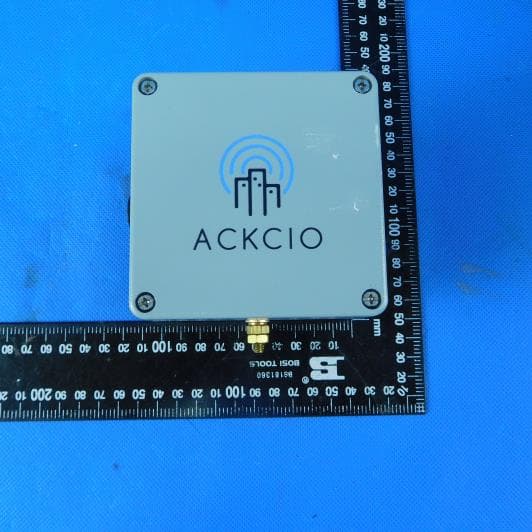
2AT8M-RN-V3X0
May 27, 2020BEAM-RN
Equipment Class
DTS - Digital Transmission System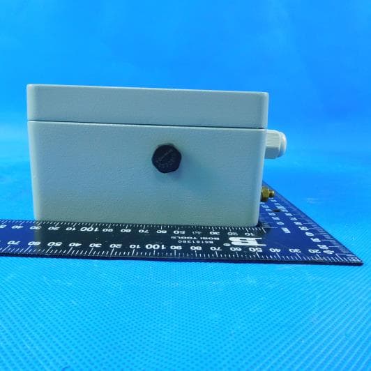
2AT8M-AN-S4-V3X0
May 27, 2020BEAM-AN-S4
Equipment Class
DTS - Digital Transmission System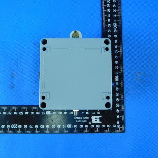
2AT8M-AN-S1-V3X0
May 27, 2020BEAM-AN-S1
Equipment Class
DTS - Digital Transmission System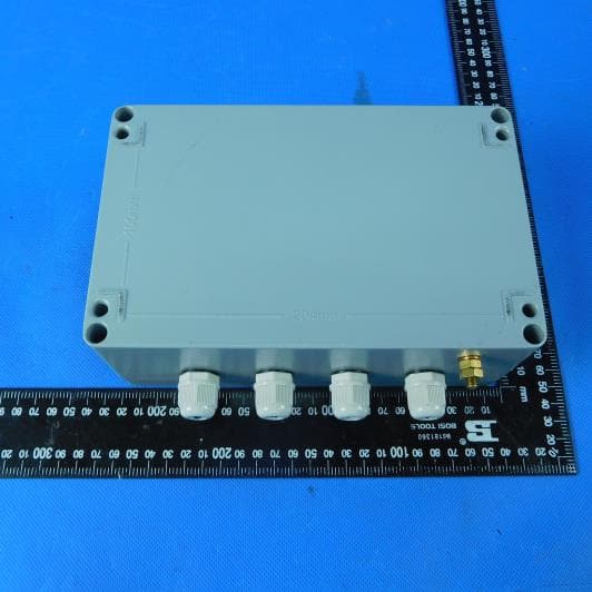
2AT8M-DG-V3X2
May 26, 2020BEAM-DG
Equipment Class
DTS - Digital Transmission System