2ATD3-IAEBT270Truly Wire-Free Earbuds
D.P.I.(H.K.) Limited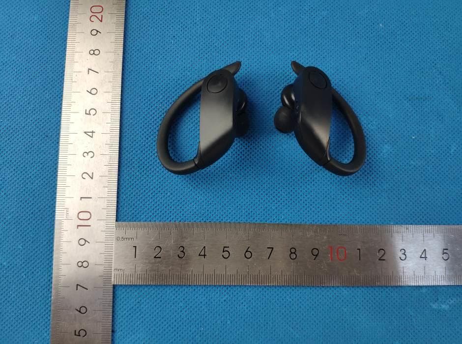
Click to zoom
Application Details
- Equipment Class
- DTS - Digital Transmission System
- Date of Grant
- Apr 06, 2020
- Application Purpose
- Original Equipment
- Date of Application
- Apr 06, 2020
- Equipment Note
- Truly Wire-Free Earbuds
- Frequency Range
- 2402.00000000 - 2480.00000000
- Company
- D.P.I.(H.K.) Limited
- Country
- China
Documents & Files
Document Text
Text extracted from the exhibit documents filed with the FCC. Open a document above to read the original.
Users Manual
Truly Wire-Free Earbuds User’s Guide for Model IAEBT270 v2470-01 Volume/Skip Press to adjust volume. Press and hold to skip ahead or back. LED Indicator Flashing red and blue= Ready to pair Solid red= Charging Note: When fully charged the light will change to blue for a few seconds and then turn off. Function Button Press and hold to power ON or OFF. Press to play or pause audio. Press to answer incoming phone call. Press quickly 2 times to manually pair. Orientation & Controls Controls are the same on both earbuds. Charging the Case Note: Placing the earbuds in the case will automatically power them OFF. • Using a USB-C to USB cable, connect to the USB port of a powered on computer or USB power adaptor (Not included). • Initial charge time is approximately 2 hours. Charge fully before use. • While the case is charging, the Case LED will display a blinking red light. When the unit is fully charged it will display a solid red light. Features • True Wireless Stereo • Sweat proof • Bluetooth Wireless: range 49 ft. • Built-in microphone • Voice prompts announce earbud operations • Digital volume control • Built-in rechargeable battery: approximately 5 hrs playtime at 50% • USB-C port for battery recharge Includes • 3 pairs of eartips: 1 small, 1 medium, 1 large • Charging case • USB-C to USB charging cable • User’s Manual Charging Contacts Case Power Button Press to activate charging. Case LED Solid blue when ON. Place earbuds onto Charging Contacts in the case to start charging. IAEBT270-2470-01-IB - 03Mar2020.indd 13/3/2020 10:43:05 AM Customer Support Customer Service: 1-888-999-4215 | Email Support: prodinfo@ dpiinc.com | Email Parts: [email protected] For Warranty Information and the most up-to-date version of this User’s Guide, go to www.iLiveElectronics.com To download this User’s Guide in English, Spanish, or French, or to get answers to frequently asked questions, visit the support section at: www.iLiveElectronics.com Para descargar este Manual del Usuario en inglés, español y francés, o para obtener respuestas a preguntas frecuentes, visite la sección de apoyo en: www.iLiveElectronics.com Pour télécharger ce guide de l’utilisateur en anglais, espagnol ou français, ou pour obtenir des réponses à des questions fréquemment posées, consultez la rubrique d’assistance sur: www.iLiveElectronics.com Copyright © 2020 Digital Products International (DPI, Inc.) All other trademarks appearing herein are the property of their respective owners. Specifications are subject to change without notice. FCC Warnings WARNING: Changes or modifications to this unit not extaply approved by the party responsible for compliance could void the user’s authority to operate the equipment. NOTE: This equipment has been tested and found to comply with the limits for a Class B digital device, pursuant to Part 15 of the FCC Rules. These limits are designed to provide reasonable protection against harmful interference in a residential installation. This equipment generates, uses, and can radiate radio frequency energy and, if not installed and used in accordance with the instructions, may cause harmful interference to radio communications. However, there is no guarantee that interference will not occur in a particular installation. If this equipment does cause harmful interference to radio or television reception, which can be determined by turning the equipment off and on, the user is encouraged to try to correct the interference by one or more of the following measures: •Reorient or relocate the receiving antenna. •Increase the separation between the equipment and receiver. •Connect the equipment into an outlet on a circuit different from that to which the receiver is connected. •Consult the dealer or an experienced radio/TV technician for help. Additional Warnings •WARNING: To prevent fire or shock hazards, do not expose this unit to rain or moisture. •WARNING : Where the mains plug or appliance coupler is used as the disconnect device, such disconnect device shall remain readily operable. •Lithium batteries, like all rechargeable batteries, are recyclable and should be recycled or disposed of according to state and local guidelines. They should never be disposed of in normal household waste, and they should never be incinerated, as they might explode. Contact your local government for disposal or recycling practices in your area. •To avoid hearing damage, make sure that the volume on your music player is turned down before connecting your headphones. After placing headphones in/on your ears, gradually turn up the volume until you reach a comfortable listening level. Speakerphone 1.To accept a call, press the Function button, or use the controls on the connected phone. 2.To end a call, press the Function button, or use the controls on the connected phone. WARNING : This product can expose you to chemicals including lead, which is known to the State of California to cause cancer and birth defects or other reproductive harm. For more information go to www.P65Warnings.ca.gov. This product meets and complies with all Federal regulations. Previously Connected Devices • Once the earbuds have been linked and connected to a device, the earbuds will auto power ON, link and connect to the last Bluetooth device whenever removed from the case. • To manually pair to another device, press the Function button quickly two times. The earbuds will enter pairing mode and can connect to a new device. • To re-connect to a different device, turn off Bluetooth on unwanted devices, then access the Bluetooth settings menu on the device you wish to use and select IAEBT270. Troubleshooting If the earbuds experience any static, delay or cutting out of sound follow these steps. 1. Make sure the earbuds are fully charged. 2. Power the earbuds OFF, then ON again. Let them reconnect automatically and try playing audio again. Repeat if needed. Made Green Initial Linking of Earbuds & Pairing to a Bluetooth Device To link the earbuds: Removing …
Text truncated - open the document above for the full version.
External Photos
1 - Page 1 of 8 - Report No.: MTi20031114-2E1-1 Tel:(86-755)88850135 Fax: (86-755) 88850136 Web: http://www.mtitest.com E-mail: [email protected] Address: No.102A & 302A, East Block, Hengfang Industrial Park, Xingye Road, Xixiang, Bao'an District, Shenzhen, Guangdong, China APPENDIX 1: EUT PHOTO Photo 1 (For model IAEBT270) Photo 2 1 - Page 2 of 8 - Report No.: MTi20031114-2E1-1 Tel:(86-755)88850135 Fax: (86-755) 88850136 Web: http://www.mtitest.com E-mail: [email protected] Address: No.102A & 302A, East Block, Hengfang Industrial Park, Xingye Road, Xixiang, Bao'an District, Shenzhen, Guangdong, China Photo 3 Photo 4 1 - Page 3 of 8 - Report No.: MTi20031114-2E1-1 Tel:(86-755)88850135 Fax: (86-755) 88850136 Web: http://www.mtitest.com E-mail: [email protected] Address: No.102A & 302A, East Block, Hengfang Industrial Park, Xingye Road, Xixiang, Bao'an District, Shenzhen, Guangdong, China Photo 5 Photo 6 1 - Page 4 of 8 - Report No.: MTi20031114-2E1-1 Tel:(86-755)88850135 Fax: (86-755) 88850136 Web: http://www.mtitest.com E-mail: [email protected] Address: No.102A & 302A, East Block, Hengfang Industrial Park, Xingye Road, Xixiang, Bao'an District, Shenzhen, Guangdong, China Photo 7 Photo 8 1 - Page 5 of 8 - Report No.: MTi20031114-2E1-1 Tel:(86-755)88850135 Fax: (86-755) 88850136 Web: http://www.mtitest.com E-mail: [email protected] Address: No.102A & 302A, East Block, Hengfang Industrial Park, Xingye Road, Xixiang, Bao'an District, Shenzhen, Guangdong, China Photo 9 Photo 10 1 - Page 6 of 8 - Report No.: MTi20031114-2E1-1 Tel:(86-755)88850135 Fax: (86-755) 88850136 Web: http://www.mtitest.com E-mail: [email protected] Address: No.102A & 302A, East Block, Hengfang Industrial Park, Xingye Road, Xixiang, Bao'an District, Shenzhen, Guangdong, China Photo 11 Photo 12 1 - Page 7 of 8 - Report No.: MTi20031114-2E1-1 Tel:(86-755)88850135 Fax: (86-755) 88850136 Web: http://www.mtitest.com E-mail: [email protected] Address: No.102A & 302A, East Block, Hengfang Industrial Park, Xingye Road, Xixiang, Bao'an District, Shenzhen, Guangdong, China Photo 13 Photo 14 1 - Page 8 of 8 - Report No.: MTi20031114-2E1-1 Tel:(86-755)88850135 Fax: (86-755) 88850136 Web: http://www.mtitest.com E-mail: [email protected] Address: No.102A & 302A, East Block, Hengfang Industrial Park, Xingye Road, Xixiang, Bao'an District, Shenzhen, Guangdong, China Photo 15 ----END OF REPORT----
Internal Photos
1 - Page 1 of 6 - Report No.: MTi20031114-2E1-1 Tel:(86-755)88850135 Fax: (86-755) 88850136 Web: http://www.mtitest.com E-mail: [email protected] Address: No.102A & 302A, East Block, Hengfang Industrial Park, Xingye Road, Xixiang, Bao'an District, Shenzhen, Guangdong, China APPENDIX 1: EUT PHOTO Photo 1 (For model IAEBT270) Photo 2 1 - Page 2 of 6 - Report No.: MTi20031114-2E1-1 Tel:(86-755)88850135 Fax: (86-755) 88850136 Web: http://www.mtitest.com E-mail: [email protected] Address: No.102A & 302A, East Block, Hengfang Industrial Park, Xingye Road, Xixiang, Bao'an District, Shenzhen, Guangdong, China Photo 3 Photo 4 1 - Page 3 of 6 - Report No.: MTi20031114-2E1-1 Tel:(86-755)88850135 Fax: (86-755) 88850136 Web: http://www.mtitest.com E-mail: [email protected] Address: No.102A & 302A, East Block, Hengfang Industrial Park, Xingye Road, Xixiang, Bao'an District, Shenzhen, Guangdong, China Photo 5 Photo 6 1 - Page 4 of 6 - Report No.: MTi20031114-2E1-1 Tel:(86-755)88850135 Fax: (86-755) 88850136 Web: http://www.mtitest.com E-mail: [email protected] Address: No.102A & 302A, East Block, Hengfang Industrial Park, Xingye Road, Xixiang, Bao'an District, Shenzhen, Guangdong, China Photo 7 Photo 8 1 - Page 5 of 6 - Report No.: MTi20031114-2E1-1 Tel:(86-755)88850135 Fax: (86-755) 88850136 Web: http://www.mtitest.com E-mail: [email protected] Address: No.102A & 302A, East Block, Hengfang Industrial Park, Xingye Road, Xixiang, Bao'an District, Shenzhen, Guangdong, China Photo 9 Photo 10 1 - Page 6 of 6 - Report No.: MTi20031114-2E1-1 Tel:(86-755)88850135 Fax: (86-755) 88850136 Web: http://www.mtitest.com E-mail: [email protected] Address: No.102A & 302A, East Block, Hengfang Industrial Park, Xingye Road, Xixiang, Bao'an District, Shenzhen, Guangdong, China Photo 11 Photo 12 ----END OF REPORT---- BT Antenna
RF Exposure Info
RF EXPOSURE REPORT FCC ID: 2ATD3-IAEBT270 Date of issue: Apr. 03, 2020 Report Number: MTi20031114-2E2 Sample Description: Truly Wire-Free Earbuds Mo d e l( s ) : IAEBT270, IAEBT270B Applicant: D.P.I.(H.K.) Limited Address: Unit 3903, 39/F, Cable TV Tower, No. 9 Hoi Shing Road, Tsuen Wan, N.T., Hong Kong Date of Test: Mar. 13, 2020 to Apr. 03, 2020 Shenzhen Microtest Co., Ltd. http://www.mtitest.com - Page 2 of 4- Report No.: MTi20031114-2E2 TEST RESULT CERTIFICATION Applicant’s name: D.P.I.(H.K.) Limited Address: Unit 3903, 39/F, Cable TV Tower, No. 9 Hoi Shing Road, Tsuen Wan, N.T., Hong Kong Manufacture's name: Shenzhen Longfuxiang Technology Co., Ltd. Address: 3 Floor, Building B, No.205, Xingye 2nd Road, Fenghuang Village, Fuyong Town, Bao'an District, Shenzhen City, Guangdong Province, China. Product name: Truly Wire-Free Earbuds Model and/or type reference: IAEBT270 Serial Model: IAEBT270B RF Exposure Procedures: KDB 447498 D01 v06 This device described above has been tested by Shenzhen Microtest Co., Ltd and the test results show that the equipment under test (EUT) is in compliance with the FCC requirements. And it is applicable only to the tested sample identified in the report. Tested by: Demi Mu Apr. 03, 2020 Reviewed by: Leo Su Apr. 03, 2020 Approved by: Tom Xue Apr. 03, 2020 - Page 3 of 4- Report No.: MTi20031114-2E2 1. Standalone SAR test exclusion considerations Unless specifically required by the published RF exposure KDB procedures, standalone 1-g head or body and 10-g extremity SAR evaluation for general population exposure conditions, by measurement or numerical simulation, is not required when the corresponding SAR Test Exclusion Threshold condition(s), listed below, is (are) satisfied. These test exclusion conditions are based on source-based time-averaged maximum conducted output power of the RF channel requiring evaluation, adjusted for tune-up tolerance, and the minimum test separation distance required for the exposure conditions. The minimum test separation distance defined in 4.1 f) is determined by the smallest distance from the antenna and radiating structures or outer surface of the device, according to the host form factor, exposure conditions and platform requirements, to any part of the body or extremity of a user or bystander. To qualify for SAR test exclusion, the test separation distances applied must be fully explained and justified, typically in the SAR measurement or SAR analysis report, by the operating configurations and exposure conditions of the transmitter and applicable host platform requirements, according to the required published RF exposure KDB procedures. When no other RF exposure testing or reporting are required, a statement of justification and compliance must be included in the equipment approval, in lieu of the SAR report, to qualify for SAR test exclusion. When required, the device specific conditions described in the other published RF exposure KDB procedures must be satisfied before applying these SAR test exclusion provisions. a) For 100 MHz to 6 GHz and test separation distances ≤ 50 mm, the 1-g and 10-g SAR test exclusion thresholds are determined by the following: [(max. power of channel, including tune-up tolerance, mW) / (min. test separation distance, mm)] · [√f(GHz)] ≤ 3.0 for 1-g SAR, and ≤ 7.5 for 10-g extremity SAR, where f (GHz) is the RF channel transmit frequency in GHz Power and distance are rounded to the nearest mW and mm before calculation The result is rounded to one decimal place for comparison The values 3.0 and 7.5 are referred to as numeric thresholds in step b) below The test exclusions are applicable only when the minimum test separation distance is ≤ 50 mm, and for transmission frequencies between 100 MHz and 6 GHz. When the minimum test separation distance is < 5 mm, a distance of 5 mm according to 4.1 f) is applied to determine SAR test exclusion. b) For 100 MHz to 6 GHz and test separation distances > 50 mm, the 1-g and 10-g SAR test exclusion thresholds are determined by the following (also illustrated in Appendix B): 1) {[Power allowed at numeric threshold for 50 mm in step a)] + [(test separation distance – 50 mm)·(f(MHz)/150)]} mW, for 100 MHz to 1500 MHz 2) {[Power allowed at numeric threshold for 50 mm in step a)] + [(test separation distance – 50 mm)·10]} mW, for > 1500 MHz and ≤ 6 GHz c) For frequencies below 100 MHz, the following may be considered for SAR test exclusion (also illustrated in Appendix C): 1) For test separation distances > 50 mm and < 200 mm, the power threshold at the corresponding test separation distance at 100 MHz in step b) is multiplied by [1 + log(100/f(MHz))] 2) For test separation distances ≤ 50 mm, the power threshold determined by the equation in c) 1) for 50 mm and 100 MHz is multiplied by ½ 3) SAR measurement procedures are not established below 100 MHz. - Page 4 of 4- Report No.: MTi20031114-2E2 When SAR test exclusion cannot be applied, a KDB inquiry is required to determine SAR evaluation requirements for any SAR test results below 100 MHz to be acceptable. 2. SAR Test Exclusion Thresholds We use 5mm as separation distance to calculate. DSS: Transmit Frequenc y (GHz) Mode Measured Power (dBm) Tune-up power (dBm) Max tune- up Result 1g SAR power(dBm) calculation 2.402 GFSK -6.116 (-6±1) -5 0.0980 3 2.441 -6.371 (-6±1) -5 0.0988 3 2.480 -6.959 (-6±1) -5 0.0996 3 2.402 π/4-DQPSK -5.183 (-6±1) -5 0.0980 3 2.441 -5.539 (-6±1) -5 0.0988 3 2.480 -6.086 (-6±1) -5 0.0996 3 DTS: Transmit Frequency (GHz) Mode Measured Power (dBm) Tune-up power (dBm) Max tune-up Result 1g SAR power(dBm) calculation 2.402 GFSK -5.857 (-5±1) -4 0.1234 3 2.440 -5.564 (-5±1) -4 0.1244 3 2.480 -5.15 (-5±1) -4 0.1254 3 Conclusion: For the max result: 0.1254≤ 3.0 for 1g SAR, No SAR is required. ----END OF REPORT----
Test Report
This test report is valid for the tested samples only. It cannot be reproduced except in full without prior written consent of Shenzhen Microtest Co., Ltd. Tel:(86-755)88850135 Fax: (86-755) 88850136 Web: http://www.mtitest.com E-mail: [email protected] Address: No.102A & 302A, East Block, Hengfang Industrial Park, Xingye Road, Xixiang, Bao'an District, Shenzhen, Guangdong, China Test Report FCC ID: 2ATD3-IAEBT270 Date of issue: Apr. 03, 2020 Report number: MTi20031114-2E3 Sample description: Truly Wire-Free Earbuds Mo d e l( s ) : IAEBT270, IAEBT270B Applicant: D.P.I.(H.K.) Limited Address: Unit 3903, 39/F, Cable TV Tower, No. 9 Hoi Shing Road, Tsuen Wan, N.T., Hong Kong Date of test: Mar. 13, 2020 to Apr. 03, 2020 Shenzhen Microtest Co., Ltd. http://www.mtitest.com - Page 2 of 45 - Report No.: MTi20031114-2E3 Tel:(86-755)88850135 Fax: (86-755) 88850136 Web: http://www.mtitest.com E-mail: [email protected] Address: No.102A & 302A, East Block, Hengfang Industrial Park, Xingye Road, Xixiang, Bao'an District, Shenzhen, Guangdong, China Table of Contents 1. GENERAL INFORMATION ................................................................................................................................... 5 1.1. DESCRIPTION OF EUT ................................................................................................................................................... 5 1.2. OPERATION CHANNEL LIST .............................................................................................................................................. 5 1.3. TEST CHANNEL LIST ....................................................................................................................................................... 6 1.4. ANCILLARY EQUIPMENT LIST ........................................................................................................................................... 6 1.5. DESCRIPTION OF SUPPORT UNITS .................................................................................................................................... 6 2. SUMMARY OF TEST RESULTS .......................................................................................................................... 7 3. TEST FACILITIES AND ACCREDITATIONS ...................................................................................................... 8 3.1. TEST LABORATORY ........................................................................................................................................................ 8 3.2. ENVIRONMENTAL CONDITIONS ........................................................................................................................................ 8 3.3. MEASUREMENT UNCERTAINTY ........................................................................................................................................ 8 3.4. TEST SOFTWARE ........................................................................................................................................................... 8 4. EQUIPMENT LIST ................................................................................................................................................. 9 5. TEST RESULT ..................................................................................................................................................... 10 5.1. ANTENNA REQUIREMENT ............................................................................................................................................. 10 5.1.1 Standard Requirement ...................................................................................................................................... 10 5.1.2 EUT Antenna ..................................................................................................................................................... 10 5.2. PEAK OUTPUT POWER TEST ......................................................................................................................................... 11 5.2.1 Limit .................................................................................................................................................................. 11 5.2.2 Test setup .......................................................................................................................................................... 11 5.2.3 Test Procedure ................................................................................................................................................... 11 5.2.4 EUT Operation Condition .................................................................................................................................. 11 5.2.5 Test Results ........................................................................................................................................................ 11 5.3. CONDUCTED EMISSION ................................................................................................................................................ 14 5.3.1 Limits ................................................................................................................................................................. 14 5.3.2 Test Setup .......................................................................................................................................................... 14 5.3.3 Test Procedure ................................................................................................................................................... 15 5.3.4 Test Results ........................................................................................................................................................ 15 5.4. RADIATED SPURIOUS EMISSION ...................................................................................................................................... 20 5.4.1 Limits .....…
Text truncated - open the document above for the full version.
Test Setup Photos
Model: IAEBT270 Radiated emission Conducted emission
Contact Information
Applicant
Alan Tang(Manager)
Test Firm
Shenzhen Microtest Co., Ltd.Selby Liao
[email protected]0755-88850135-1193
Technical Specifications
| # | Rule Parts | Frequency Range | Power Output |
|---|---|---|---|
| 1 | 15C | 2.40 GHz - 2.48 GHz | 310.00 µW |
Other Applications from D.P.I.(H.K.) Limited
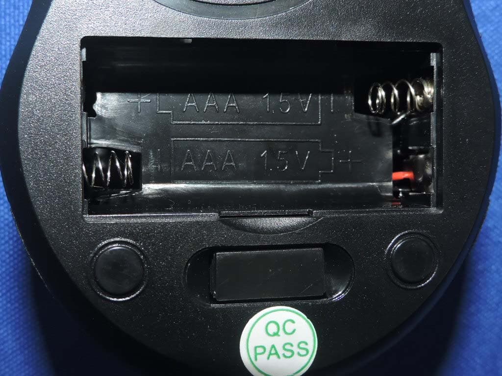
2ATD3-IAMW20B
Oct 31, 2020Wireless Mouse
Equipment Class
DXX - Part 15 Low Power Communication Device Transmitter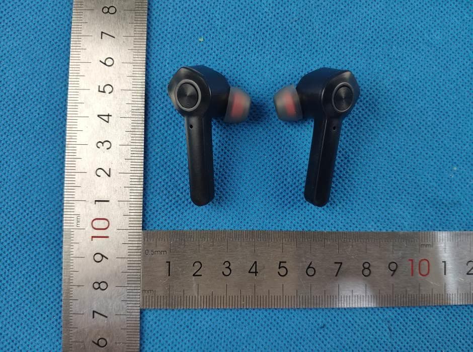
2ATD3-IAEBT300
Jan 14, 2020Truly Wire-Free Earbuds
Equipment Class
DTS - Digital Transmission System