2ATFX-101941DT-RFIO-Module (US)
Disruptive Technologies Research AS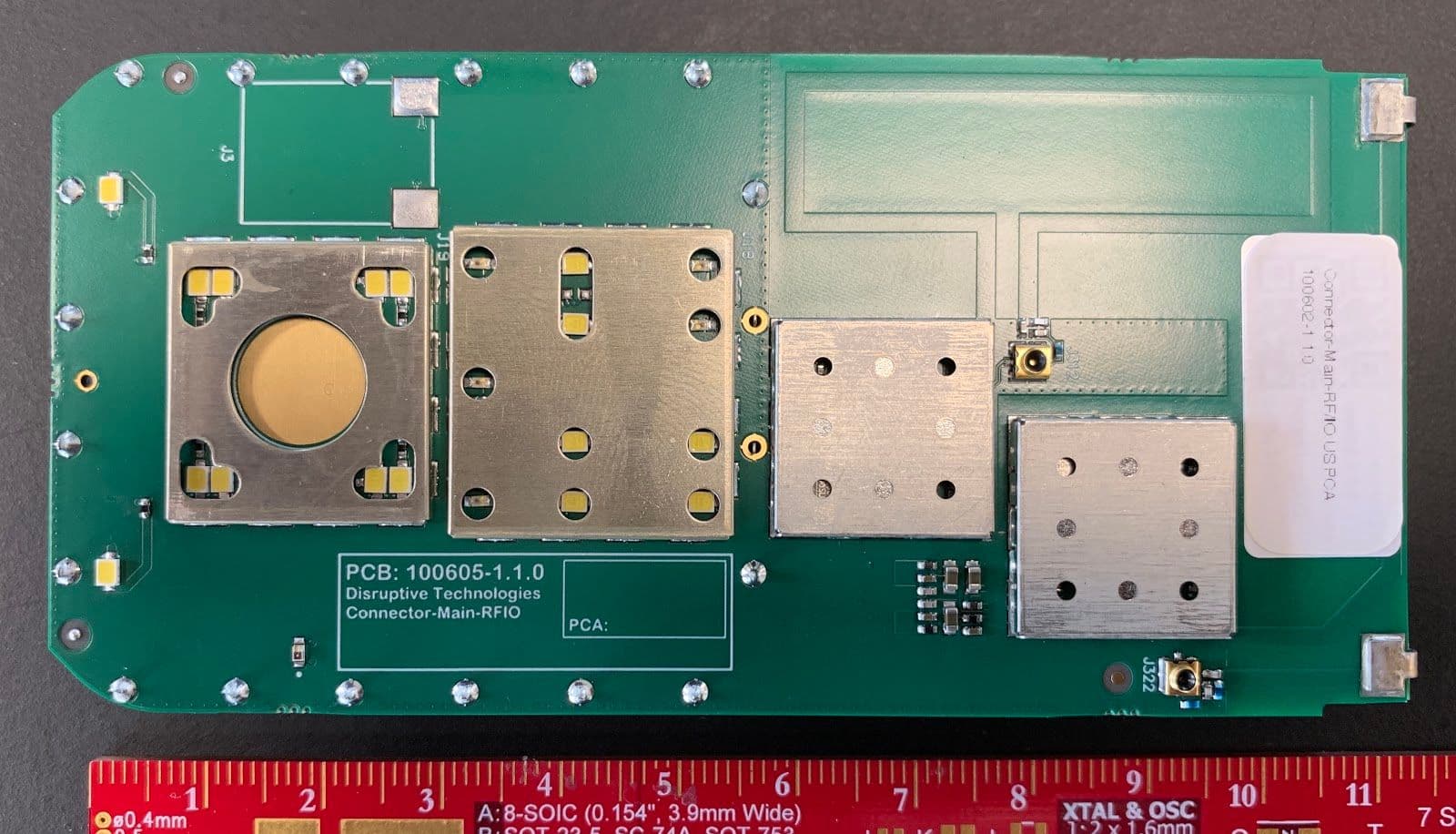
Click to zoom
Application Details
- Equipment Class
- DTS - Digital Transmission System
- Date of Grant
- Aug 19, 2020
- Application Purpose
- Original Equipment
- Date of Application
- Aug 19, 2020
- Equipment Note
- DT-RFIO-Module (US)
- Frequency Range
- 903.25000000 - 926.75000000
- Country
- Norway
Documents & Files
Document Text
Text extracted from the exhibit documents filed with the FCC. Open a document above to read the original.
Cover Letter(s)
August 19 - 2020 Telecommunication Certification Body UL VS Ltd Unit 1-3, Horizon Wade Road Kingsland Business Park Basingstoke Hampshire RG24 8AH United Kingdom Subject: Authorisation Letter To whom it may concern This is to certify that Disruptive Technologies Research AS hereby authorises UL VS Ltd. to act as the TCB for the application of the DT-RFIO-Module (US), FCC ID: 2ATFX- 101941 to the FCC. We certify that we are not subject to a denial of Federal benefits, that include FCC benefits, pursuant to Section 5301 of the Anti-Drug Abuse Act of 1988, 21 U.S.C. § 862 because of a conviction for possession or distribution of a controlled substance. See 47 CFR 1.2002(b) for the definition of a "party" for these purposes. Yours faithfully, Oystein Moldsvor VP Engineering
Cover Letter(s)
August 19 2020 Telecommunication Certification Body UL VS Ltd Unit 1-3, Horizon Wade Road Kingsland Business Park Basingstoke Hampshire RG24 8AH United Kingdom Subject: Permanent Confidentiality Request Certification Application FCC ID: 2ATFX-101941 To whom it may concern Pursuant to Sections 0.457(d) and 0.459 of CFR 47 , Disruptive Technologies Research AS request that the following information, provided to support the FCC application for the DT-RFIO-Module (US), FCC ID: 2ATFX-101941 to be held permanently confidential: Schematics Block Diagrams Parts List Operational Description The above material contains trade secrets not customarily released to public that are judged to have the potential to cause detriment to the applicant and provide unjustified benefits to its competitors. This information should not be available for public disclosure for an indefinite period of time. Yours faithfully, Oystein Moldsvor VP Engineering
Cover Letter(s)
August 19. 2020 Telecommunication Certification Body UL VS Ltd Units 1-3, Horizon Wade Road Kingsland Business Park Basingstoke Hampshire RG24 8AH United Kingdom Subject: FCC Limited Single-Modular Approval Letter FCC ID: 2ATFX-101941 To whom it may concern We, Disruptive Technologies Research AS hereby declare that the product, FCC ID: 2ATFX-101941 has met the single-modular approval requirements of FCC rule part §15.212(a)(1) and this is shown in the table below. Furthermore, we declare that the module DT-RFIO-Module (US), is not for sale – it is for use in Disruptive Technologies Research AS manufactured host devices only and the user manual integration instructions are internal confidential manufacturing documents Requirement Compliance: Yes or No along with a justification The radio elements must have the radio frequency circuitry shielded. Physical components and tuning capacitor(s) may be located external to the shield, but must be on the module assembly Yes. As described in the Operational Description and Internal Photos The module must have buffered modulation/data inputs to ensure that the Yes. As described in the Operational Description device will comply with Part 15 requirements with any type of input signal The module must contain power supply regulation on the module Yes. As described in the Operational Description The module must contain a permanently attached antenna, or contain a unique antenna connector, and be marketed and operated only with specific antenna(s), per Sections 15.203, 15.204(b), 15.204(c), 15.212(a), 2.929(b) Yes. As described in the Operational Description and Internal Photos The module must demonstrate compliance in a stand-alone configuration Yes. The system is tested and compliant in a stand-alone configuration The module must be labelled with its permanently affixed FCC ID label, or use an electronic display (See KDB Publication 784748 about labelling requirements) Yes. The FCC ID is printed on the PCB as shown in the Labels exhibit The module must comply with all specific rules applicable to the transmitter including all the conditions provided in the integration instructions by the grantee Yes, see User Guide The module must comply with RF exposure requirements Yes, see RF exposure exhibit Yours faithfully, Oystein Moldsvor VP Engineering
External Photos
Document ID https://docs.google.com/document/ d/1UoGLFL0qKUqnG_a4sh0Q3ybI wBxe2NGBExlG3zo81k8/edit#hea ding=h.dku7xb2o5sj0 Responsible Oystein Moldsvor Classification Confidential Revision History Table Named revision Date Comment: 01 2020-06-30 First version shared with UL 7) External Photos Figure 1: Picture of the top of the part 101941 DT-RFIO-Module (US) Figure 2: Picture of the bottom of the part 101941 DT-RFIO-Module (US)
ID Label/Location Info
Document ID https://docs.google.com/document/ d/11FC9wTU6rn4YL7nV0K1VtvXh cN2gION_FcI-yzexsP0/edit Responsible Oystein Moldsvor Classification Confidential Revision History Table Named revision Date Comment: 01 2020-03-30 First version shared with UL 9) Labels Instructions: “This exhibit can be submitted as one or two documents: One document showing the both label content and location or two documents showing individually the label content and label location. A photograph can be submitted for this exhibit BUT the photo must be submitted in PDF format.” Figure 1: Picture of location of label on 101941 The FCC ID and IC are printed in 4.57 point fonts. Figure 2: Picture of content of label (part no. 101942)
Internal Photos
Document ID https://docs.google.com/document/ d/1JEhjaGp8KkxRLlHKm-QlQDed EpljQzpTYs3yLK3NE-A/edit# Responsible Oystein Moldsvor Classification Confidential Revision History Table Named revision Date Comment: 01 2020-06-30 First version shared with UL 02 2020-07-08 Added more detail 8) Internal Photos Instructions: “Clear sharp focused views of the internals of the device including close up shots of all PCBs (top and bottom, with and without RF shields). It must be possible to identify individual components on PCBs. The photos must be clear and Photos must be taken vertically straight down not angled. All photos are to be placed in a single PDFed exhibit” Figure 1: Picture of top of part 101941 DT-RFIO-Module (US). Only the lids are removed from the two shield boxes to the right. ANT1 and 2 are indicated. ANT2 extends onto the bent part of the board, as indicated in Figure 2. Figure 2: Picture of top of part 101941 DT-RFIO-Module (US). All shields are removed. ANT1 and 2 are indicated. ANT2 extends onto the bent part of the board, as indicated by the dotted line. Figure 3: Picture of the bottom of the part 100602 Connector-Main-RF/IO US PCA. Only the lids are removed from the two shield boxes. The traces of the antennas go on the other side of the PCB. Figure 4: Picture of the bottom of the part 100602 Connector-Main-RF/IO US PCA. The shields are completely removed from the shield boxes and the extension of ANT2 onto the bent part of the board is indicated by the dotted line. The traces of the antennas go on the other side of the PCB.
RF Exposure Info
Page 1 of 2 RF Exposure and Transmitter Power Considerations for DT-RFIO-Module (US) FCC ID: 2ATFX-101941 The FCC requires that the calculated MPE be equal to or less than a given limit dependent on frequency at a distance of 20 cm from a device to the body of a user. The Cloud Connector US equipment operates in the 902 MHZ – 928 MHz band. The following FCC Rule Parts and procedures are applicable: Part 1.1310 – Radiofrequency radiation exposure limits Part 2.1091 – Radiofrequency radiation exposure evaluation: mobile devices MPE CALCULATIONS The MPE calculation used to calculate the safe operating distance for the user is: S = EIRP/4 π R 2 WhereS = Power density EIRP = Effective Isotropic Radiated Power (EIRP = P x G) P = Conducted Transmitter Power G = Antenna Gain (relative to an isotropic radiator) R = distance to the centre of radiation of the antenna (safe operating distance) Values: Transmitter frequency range = 902 MHZ – 928 MHz Power = 25 dBm (316.2 mW) G = 0 dBi EIRP = 25 dBm (316.2 mW) R = 20cm Page 2 of 2 Power Density Requirement From table 1 (b) - Limits for General Population/ Uncontrolled Exposure of FCC Rule Part 1.1310 for 902 – 928 MHz S = f/1500 mW/cm 2 (f = operating frequency) S req = 902/1500 = 0.60 mW/cm 2 Calculation: S = EIRP/4 π R 2 S= 316.2 /(12.56 x 20 2 ) S = 316.2 /(5024) S = 0.063 mW/ cm 2 (<0.60 mW/cm 2 ) This equates to a safe operating distance of 6.5 cm Signature: ________________________________________ Date: ___________________ 2020-07-08
Test Setup Photos
Disruptive Technologies AS FCC ID: 2ATFX-101941 UL-RPT-RP13194272 IC: 25087-101941 UL VS LTD 1 Test Setup Photographs for the Cloud Connector US 4G 1. Radiated Emissions 1.1. Configuration 1: Radiated Band edge measurements. Photo 1 Disruptive Technologies AS FCC ID: 2ATFX-101941 UL-RPT-RP13194272 IC: 25087-101941 UL VS LTD 2 Radiated Emissions (continued) Photo 2 Photo 3 Disruptive Technologies AS FCC ID: 2ATFX-101941 UL-RPT-RP13194272 IC: 25087-101941 UL VS LTD 3 Radiated Emissions (continued) 1.2. Configuration 2: Radiated measurements <1 GHz Photo 1 Photo 2 Disruptive Technologies AS FCC ID: 2ATFX-101941 UL-RPT-RP13194272 IC: 25087-101941 UL VS LTD 4 Radiated Emissions (continued) Photo 3 Disruptive Technologies AS FCC ID: 2ATFX-101941 UL-RPT-RP13194272 IC: 25087-101941 UL VS LTD 5 Radiated Emissions (continued) 1.3. Configuration 2: Radiated measurements >1 GHz Photo 1 Disruptive Technologies AS FCC ID: 2ATFX-101941 UL-RPT-RP13194272 IC: 25087-101941 UL VS LTD 6 Photo 2 Disruptive Technologies AS FCC ID: 2ATFX-101941 UL-RPT-RP13194272 IC: 25087-101941 UL VS LTD 7 AC Conducted Emissions 1.4. Configuration 1: Test set-up with PSU Photo 1 Photo 2 Disruptive Technologies AS FCC ID: 2ATFX-101941 UL-RPT-RP13194272 IC: 25087-101941 UL VS LTD 8 Photo 3 Disruptive Technologies AS FCC ID: 2ATFX-101941 UL-RPT-RP13194272 IC: 25087-101941 UL VS LTD 9 Conducted RF Tests Photo 1
Contact Information
Applicant
Oystein Moldsvor
Technical Contact
Disruptive Technologies Research ASOystein Moldsvor
[email protected]+47 93037141
Strandveien 17 · Lysaker · Norway
Non-Technical Contact
Disruptive Technologies Research ASBengt J Lundberg
[email protected]+47 91633887
Test Firm
UL VS LtdDarren Rust
Technical Specifications
| # | Rule Parts | Frequency Range | Power Output |
|---|---|---|---|
| 1 | 15C | 903.25 MHz - 926.75 MHz | 245.00 mW |
Other Applications from Disruptive Technologies Research AS
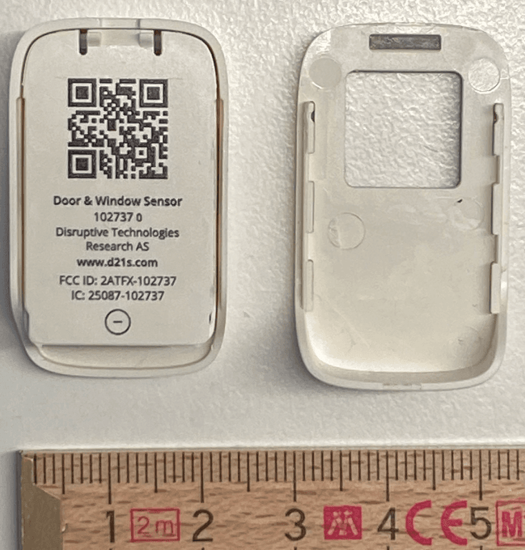
2ATFX-102737
Feb 14, 2024A wireless sensor used to detect if doors and windows are opened or closed.
Equipment Class
DTS - Digital Transmission System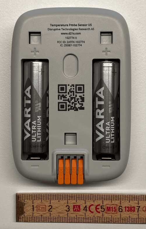
2ATFX-102774
Feb 13, 2024A wireless temperature sensor using an external PT100 temperature sensor element.
Equipment Class
DTS - Digital Transmission System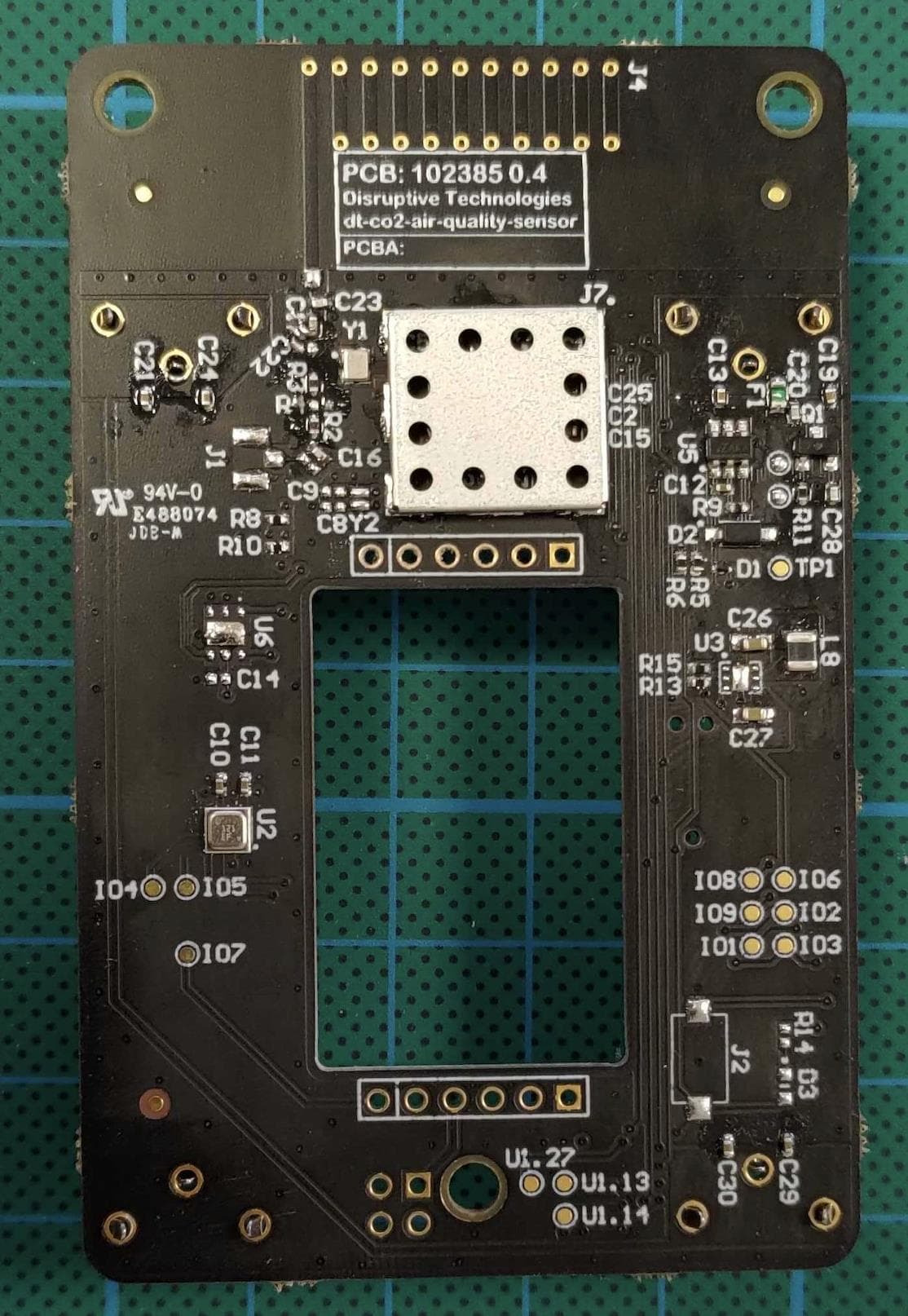
2ATFX-102540
Dec 13, 2022A platform for connecting various sensors to the RF network of Disruptive Technologies
Equipment Class
DSS - Part 15 Spread Spectrum Transmitter