2ATFX-102540A platform for connecting various sensors to the RF network of Disruptive Technologies
Disruptive Technologies Research AS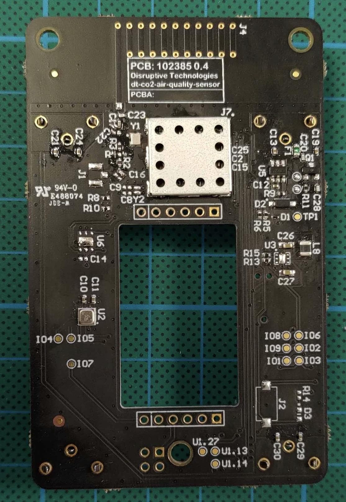
Click to zoom
Application Details
- Equipment Class
- DSS - Part 15 Spread Spectrum Transmitter
- Date of Grant
- Dec 13, 2022
- Application Purpose
- Original Equipment
- Date of Application
- Dec 13, 2022
- Equipment Note
- A platform for connecting various sensors to the RF network of Disruptive Technologies
- Frequency Range
- 903.25000000 - 926.75000000
- Country
- Norway
Documents & Files
Document Text
Text extracted from the exhibit documents filed with the FCC. Open a document above to read the original.
Users Manual
Sensor RF module 2AA (US) User Manual Document IDhttps://docs.google.com/document/ d/1vMAhCm9pQoFzbRcb5lRH9eX EqCiIzz2H/edit ResponsibleØystein Moldsvor ClassificationPublic Sensor RF module 2AA (US) - 102540 - User Manual Summary: The Sensor RF module 2AA (US)shall be used only ininternal Disruptive Technologies productsand is mounted inside the products duringmanufacturing according to a manufacturing flow developed and maintained by Disruptive Technologies engineers. A simple installation guide is given for reference only. The Sensor RF module 2AA (US) is designed to support the proprietary RF protocol Secure Data Shot (SDS) of Disruptive Technologies and shall be used in devices for establishing an RF link with SDS enabled devices. Revision History Table Named revisionDate + TIme stamp YYYY-MM-DD HR:MM Tag name: Document started, Document ready for review, Document approved 2022-04-28First version shared with TÜV ThisdocumentcontainsproprietaryinformationforDisruptiveTechnologiesASandshouldbedistributedonly accordingtotheintendedclassificationgivenontopofthepage.Informationinthisdocumentmaybeusedin DisruptiveTechnologiesASpatentapplications.DisruptiveTechnologiesASisnotresponsibleorliableforanylossor damage arising from use of information herein. IMPORTANT NOTICE: Paper copies are not controlled, only electronic versions shall be used, ref. DTQS. Disruptive Technologies AS - Public1of7 Sensor RF module 2AA (US) User Manual Table of Content 1. Installation and use of the module 2. General description 3. Compliance Statement 4. Block Diagram 5. Antenna requirements 6. Electrical Interface Disruptive Technologies AS - Public2of7 Sensor RF module 2AA (US) User Manual 1. Installation and use of the module TheSensorRFmodule2AA(US)shallbeusedonlyininternalDisruptiveTechnologies productsandismountedinsidetheproductsduringmanufacturingaccordingtoa manufacturingflowdevelopedandmaintainedbyDisruptiveTechnologiesengineers.Asimple installation guide is given for reference only. 2. General description TheSensorRFmodule2AA(US),withpartnumber102540,isdesignedtosupportthe proprietaryDisruptiveTechnologiesRFprotocol,SecureDataShot(SDS).Themoduleshallbe used in products for establishing an RF link with SDS enabled gateways. TheSensorRFmodule2AA(US)containsoneradioICandaninternalPCBantennatogether withadigitalinterfacethatismeanttobeusedforconnectingvariousdigitalsensingelements or modules. Details can be found in the “Block Diagram” section in this document. Additionally,themodulesupportspowermanagementcircuitrytoallowthedevicetobe poweredfrombatteriesandbeisolatedfromthevariationinbatteryvoltage.Thetypicalpower supply is two AA batteries. 3. Compliance Statement The FCC and Industry Canada statements as printed below apply to the Sensor RF module 2AA (US). The FCC and Industry Canada statements must be included in the user manual of any host product incorporating the module and both must be printed on the host product exterior if it is big enough to accommodate the print. FCC (Federal Communications Commission) statements This device complies with Part 15 of the FCC Rules. Operation is subject to the following two conditions: 1) The device may not cause harmful interference, and 2) The device Module must accept any interference received, including interference that may cause undesired operation. This device complies with FCC RF radiation exposure limits set forth for an uncontrolled environment. The antenna used for this transmitter must be installed to provide a separation distance of at least 20 cm from all persons and must not be co-located or operating in conjunction with any other antenna or transmitter. Important Note: This equipment has been tested and found to comply with the limits for a Class B digital device, pursuant to Part 15 of the FCC Rules. These limits are designed to provide reasonable protection against harmful interference in a residential installation. This equipment generates, uses and can radiate radio frequency energy and, if not installed and used in accordance with the instructions, may cause harmful interference to radio communications. However, there is no guarantee that interference will not occur in a particular installation. Disruptive Technologies AS - Public3of7 Sensor RF module 2AA (US) User Manual This transmitter must not be co-located or operating in conjunction with any other antennas or transmitters. It is the responsibility of the host device manufacturer to ensure continued compliance with FCC rule part 15B once the module has been installed in the host device. Changes or modifications not expressly approved by the party responsible for compliance could void the user's authority to operate the equipment. The concerned end product must be labeled to say “Contains FCC ID: 2ATFX-102540” Industry Canada statements This device complies with Industry Canada licence-exempt RSS standard(s). Operation is subject to the following two conditions: 1) The device may not cause interference, and 2) The device must accept any interference, including interference that may cause undesired operation of the device. Important note: To comply with Industry Canada RF exposure limits, the antenna used for this device must be installed to provide a separation distance of at least 20cm from all persons. RF exposure is in accordance with RSS-102, section 2.5.2. The concerned end product must be labelled to say: “Contains IC: 25087-102540” Declarations d’Industry Canada Cet equipement est conforme aux normes d’exemption de licence RSS d’Industry Canada. Son utilisation est soumise aux deux conditions suivantes: 1) Le dispositif ne doit pas provoquer d’interference, et 2) Le dispositif doit accepter toute interference, y compris des interferences susceptibles de provoquer un fonctionnement indesirable de l’equipement. Remarque importante: Pour respecter les limites d’exposition aux radiofrequences d’Industry Canada, l'antenne utilisée pour cet appareil doit être installé pour fournir une …
Text truncated - open the document above for the full version.
Cover Letter(s)
Authorization Letter I hereby authorize Kennet Palm to handle the FCC and ISED application processes on behalf of Disruptive Technologies Research AS. Best Regards Oystein Moldsvor VP Engineering Disruptive Technologies Research AS1of2 2022-06-14 Disruptive Technologies Research AS2of2
Cover Letter(s)
August 10 20220 TUV SUD BABT UNLIMITED Octagon House Concorde Way Segensworth North Fareham Hampshire PO15 5RL United Kingdom Subject: Permanent Confidentiality Request Certification Application FCC ID: 2ATFX-102540 To whom it may concern Pursuant to Sections 0.457(d) and 0.459 of CFR 47, Disruptive Technologies Research AS request that the following information, provided to support the FCC application for the Sensor RF module 2AA (US), FCC ID: 2ATFX-102540 to be held permanently confidential: Schematics Block Diagrams Parts List Operational Description Theabovematerialcontainsdetaileddescriptionsofanewinnovatypeofdevice.It containstradesecretsnotcustomarilyreleasedtopublicthatarejudgedtohavethe potentialtocausedetrimenttotheapplicantandprovideunjustifiedbenefitstoits competitors,inparticularconsideredthattheapplicantisayoungcompanyestablishing itselfinthemarket.Thisinformationshouldnotbeavailableforpublicdisclosureforan indefinite period of time. Yours faithfully, Oystein Moldsvor VP Engineering 2022-08-08
Cover Letter(s)
August 10. 2022 TUV SUD BABT UNLIMITED Octagon House Concorde Way Segensworth North Fareham Hampshire PO15 5RL United Kingdom Subject: FCC Limited Single Modular Approval Letter FCC ID: 2ATFX-102540 To whom it may concern We, Disruptive Technologies Research AS hereby declare that the product, FCC ID: 2ATFX-102540 has met the single-modular approval requirements of FCC rule part §15.212(a)(1) and this is shown in the table below. Furthermore, we declare that the module Sensor RF module 2AA (US) , is not for sale – it is for use in Disruptive Technologies Research AS manufactured host devices only and the user manual integration instructions are internal confidential manufacturing documents. RequirementCompliance: Yes or No along with a justification The radio elements must have the radio frequency circuitry shielded. Physical components and tuning capacitor(s) may be located external to the shield, but must be on the module assembly Yes. As described in the Operational Description and Internal Photos The module must have buffered modulation/data inputs to ensure that the Yes. As described in the Operational Description device will comply with Part 15 requirements with any type of input signal The module must contain power supply regulation on the module Yes. As described in the Operational Description The module must contain a permanently attached antenna, or contain a unique antenna connector, and be marketed and operated only with specific antenna(s), per Sections 15.203, 15.204(b), 15.204(c), 15.212(a), 2.929(b) Yes. As described in the Operational Description and Internal Photos The module must demonstrate compliance in a stand-alone configuration Yes. The system is tested and compliant in a stand-alone configuration The module must be labelled with its permanently affixed FCC ID label, or use an electronic display (See KDB Publication 784748 about labelling requirements) Yes. The FCC ID is printed on the PCB as shown in the Labels exhibit The module must comply with all specific rules applicable to the transmitter including all the conditions provided in the integration instructions by the grantee Yes, see User Guide The module must comply with RF exposure requirements Yes, see RF exposure exhibit Yours faithfully, Oystein Moldsvor VP Engineering 2022-08-08
External Photos
Document ID https://docs.google.com/document/ d/11yGOBV3KzpLo5o6WCA2CuN _QPSc1H_Vp/edit# Responsible Oystein Moldsvor Classification Confidential Revision History Table Named revision Date Comment: 01 2022-04-28 First version shared with TÜV SÜD External Photos Figure 1: Picture of component side of part 102540 - Sensor RF module 2AA (US). The RF shield box is mounted. The antenna location is at the top of the PCB Figure 2: Picture of bottom side of part 102540 - Sensor RF module 2AA (US). The antenna location is at the top of the PCB Figure 3: Picture of the label location
ID Label/Location Info
Document ID https://docs.google.com/document/ d/1MUvGkfWLgCSA7L1KBUDgkY L5p711pKcB/edit Responsible Oystein Moldsvor Classification Confidential Revision History Table Named revision Date Comment: 01 2022-04-28 First version 9) Labels Figure 1: Picture of location of label on 102540 The FCC ID and IC are printed in 1 mm tall characters. Figure 2: Picture of content of the label (part no. 102541)
Internal Photos
Document ID https://docs.google.com/document/ d/1c5pM65_WuV6NdR8a4- MC0ETZ7v8vC07E/edit Responsible Oystein Moldsvor Classification Confidential Revision History Table Named revision Date Comment: 01 2022-04-28 First version shared with TÜV SÜD Internal Photos Figure 1: Picture of component side of part 102540 - Sensor RF module 2AA (US). The RF shield box is removed. The antenna location is at the top of the PCB Figure 2: Picture of bottom side of part 102540 - Sensor RF module 2AA (US). The antenna location is at the top of the PCB Figure 3: Picture of the label location
RF Exposure Info
TÜV SÜD, Octagon House, Concorde Way, Segensworth North, Fareham, Hampshire, United Kingdom, PO15 5RL Tel: +44 (0) 1489 558100 Website: www.tuvsud.com/en COMMERCIAL-IN-CONFIDENCE Approved by Date 04 July 2022 Matt Russell Authorised Signatory ©2022 Not to be reproduced, except in its entirety, without the permission of TÜV SÜD Document 75954104-15 Issue 01 Contains FCC ID: 2ATFX-102540 915 MHz Transmitter: FCC General RF Exposure Test Exemption Guidance (KDB 447498 D04 v01 Appendix B) SAR or MPE based evaluation is not required if any of the applicable Steps 1, 2 or 3 are met (Ref: KDB 447448 Figure A.1). Step 1: All Devices: Blanket 1 mW Exemption (100 kHz – 100 GHz) Reference: FCC CFR 47 Part 1.1307(b)(3)(i)(A). Frequency (MHz) Conducted Power Output mW Duty Cycle % Time Average Conducted Power Output mW Antenna Gain Ratio Maximum Power (EIRP) mW Maximum Power (ERP) mW Test Separation Distance (mm) All devices: 1.1307(b)(3)(i)(A)Blanket 1 mW Exemption (Yes/No)* (100 kHz to 100 GHz) 915 15.84893192 0.000001 1.58489E-07 0.83176 1.31825E-07 0.00 250 Yes *Based on conducted power output or ERP whichever is greater, compared to the 1 mW exemption threshold. ©2022 Not to be reproduced, except in its entirety, without the permission of TÜV SÜD Page 2 of 2 Document Number: 75954104-14 | Issue: 01 COMMERCIAL-IN-CONFIDENCE The SAR and MPE exclusion thresholds have been evaluated using the formula described above from information supplied by the manufacturer below. Based on the calculations above, the product is categorically excluded from SAR or MPE evaluation. Manufacturer’s Declaration of Product information: Technical Description: (Please provide a brief description of the intended use of the equipment) The “Sensor RF module 2AA (US)” is a platform for connecting various sensors to the RF network of Disruptive Technologies. The module reads values from a connected sensor and converts the data into the right format for transmission on air using the proprietary SDS protocol. The device is battery operated. Manufacturer: Zollner Elektronik AG, Manfred-Zollner-Str. 1, 93499 Zandt, Germany Model: Sensor RF module 2AA (US) Part Number: 102540 If more than one frequency band is supported, please confirm which combinations of bands are capable of Simultaneous Transmit. Frequency Band 1: 915 MHz ISM band . Antenna Model: PCB antenna Antenna length: 14 cm Middle frequency: 915 MHz Maximum power (input to the antenna including a tolerance): 12 dBm Antenna gain (or maximum gain allowed): -0.8 dBi Or Field Strength Measurement: dBμA/M Measurement Distance: cm Separation distance from antenna to the user/bystander 25 cm Transmitter Duty Cycle: 0.000001 %
Test Report
TÜV SÜD is a trading name of TUV SUD Ltd Registered in Scotland at East Kilbride, Glasgow G75 0QF, United Kingdom Registered number: SC215164 TUV SUD Ltd is a TÜV SÜD Group Company Phone: +44 (0) 1489 558100 Fax: +44 (0) 1489 558101 www.tuvsud.com/en TÜV SÜD Octagon House Concorde Way Fareham Hampshire PO15 5RL United Kingdom TÜV SÜD SIGNATURE NAME JOB TITLE RESPONSIBLE FOR ISSUE DATE Steve Marshall Senior engineer Authorised Signatory 14 June 2022 Signatures in this approval box have checked this document in line with the requirements of TÜV SÜD document control rules. ENGINEERING STATEMENT The measurements shown in this report were made in accordance with the procedures described on test pages. All reported testing was carried out on a sample equipment to demonstrate limited compliance with FCC 47 CFR Part 15C, ISED RSS-247 and ISED RSS-GEN. The sample tested was found to comply with the requirements defined in the applied rules. RESPONSIBLE FOR NAME DATE SIGNATURE Testing Thomas Biddlecombe 14 June 2022 Testing Graeme Lawler 14 June 2022 FCC Accreditation 90987 Octagon House, Fareham Test Laboratory ISED Accreditation 12669A Octagon House, Fareham Test Laboratory EXECUTIVE SUMMARY A sample of this product was tested and found to be compliant with FCC 47 CFR Part 15C: 2020, ISED RSS-247: Issue 2 (02- 2017) and ISED RSS-GEN: Issue 5 (04-2018) + A2 (02-2021) for the tests detailed in section 1.3. FCC and ISED Test Report Disruptive Technologies Research AS Model: Sensor RF module 2AA (US) In accordance with FCC 47 CFR Part 15C, ISED RSS-247 and ISED RSS-GEN (Short Range Device) Prepared for: Disruptive Technologies Research AS Strandveien 17 1366 Lysaker Norway FCC ID: 2ATFX-102540 IC ID: 25087-102540 COMMERCIAL-IN-CONFIDENCE Document 75954104-06 Issue 01 DISCLAIMER AND COPYRIGHT This non-binding report has been prepared by TÜV SÜD with all reasonable skill and care. The document is confidential to the potential Client and TÜV SÜD. No part of this document may be reproduced without the prior written approval of TÜV SÜD. © 2022 TÜV SÜD. This report relates only to the actual item/items tested. ACCREDITATION Our UKAS Accreditation does not cover opinions and interpretations and any expressed are outside the scope of our UKAS Accreditation. Results of tests not covered by our UKAS Accreditation Schedule are marked NUA (Not UKAS Accredited). Document 75954104-06 Issue 01 COMMERCIAL-IN-CONFIDENCE COMMERCIAL-IN-CONFIDENCE Page 1 of 59 Contents 1 Report Summary ......................................................................................................................... 2 1.1 Report Modification Record ........................................................................................................... 2 1.2 Introduction .................................................................................................................................... 2 1.3 Brief Summary of Results ............................................................................................................. 3 1.4 Application Form ........................................................................................................................... 4 1.5 Product Information ....................................................................................................................... 7 1.6 Deviations from the Standard ........................................................................................................ 7 1.7 EUT Modification Record .............................................................................................................. 7 1.8 Test Location ................................................................................................................................. 7 2 Test Details .................................................................................................................................. 8 2.1 Emission Bandwidth ...................................................................................................................... 8 2.2 Maximum Conducted Output Power ........................................................................................... 12 2.3 Spurious Radiated Emissions ..................................................................................................... 14 2.4 Authorised Band Edges .............................................................................................................. 46 2.5 Power Spectral Density ............................................................................................................... 49 3 Photographs .............................................................................................................................. 53 3.1 Test Setup Photographs ............................................................................................................. 53 4 Measurement Uncertainty ........................................................................................................ 59 Document 75954104-06 Issue 01 COMMERCIAL-IN-CONFIDENCE COMMERCIAL-IN-CONFIDENCE Page 2 of 59 1 Report Summary 1.1 Report Modification Record Alterations and additions to this report will be issued to the holders of each copy in the form of a complete document. Issue Description of Change Date of Issue 1 First Issue 14-June-2022 Table 1 1.2 Introduction Applicant Disruptive Technologies Research AS Manufacturer Disruptive Technologies Research AS Model Number(s) Sensor RF module 2AA (US) Serial Number(s) US 2 Hardware Version(s) 0 Software Version(s) 1.2.28 Number of Samples Tested 1 Test Specification/Issue/Date FCC 47 CFR Part 15C: 2020 ISED RSS-247: Issue 2 (02-2017) ISED RSS-GEN: Issue 5 (04-2018) + A2 (02-2021) Order Number Date DK-12 14-December-2021 Date of Receipt of EUT 17-February-2022 Start of Test 14-March-2022 Finish of Test 29-April-2022 Name of Engineer(s) Thomas Biddlecombe and Graeme Lawler Related Document(s) ANSI C63.10 (2013) D…
Text truncated - open the document above for the full version.
Test Setup Photos
Document 75954104-06 Issue 01 COMMERCIAL-IN-CONFIDENCE COMMERCIAL-IN-CONFIDENCE Page 53 of 59 3 Photographs 3.1 Test Setup Photographs Figure 63 - Test Setup - 30 MHz to 1 GHz - X Orientation Document 75954104-06 Issue 01 COMMERCIAL-IN-CONFIDENCE COMMERCIAL-IN-CONFIDENCE Page 54 of 59 Figure 64 - Test Setup - 30 MHz to 1 GHz - Y Orientation Document 75954104-06 Issue 01 COMMERCIAL-IN-CONFIDENCE COMMERCIAL-IN-CONFIDENCE Page 55 of 59 Figure 65 - Test Setup - 30 MHz to 1 GHz - Z Orientation Document 75954104-06 Issue 01 COMMERCIAL-IN-CONFIDENCE COMMERCIAL-IN-CONFIDENCE Page 56 of 59 Figure 66 - Test Setup - 1 GHz to 10 GHz - X Orientation Document 75954104-06 Issue 01 COMMERCIAL-IN-CONFIDENCE COMMERCIAL-IN-CONFIDENCE Page 57 of 59 Figure 67 - Test Setup - 1 GHz to 10 GHz - Y Orientation Document 75954104-06 Issue 01 COMMERCIAL-IN-CONFIDENCE COMMERCIAL-IN-CONFIDENCE Page 58 of 59 Figure 68 - Test Setup - 1 GHz to 10 GHz - Z Orientation
Contact Information
Applicant
Oystein Moldsvor
Test Firm
TUV SUD LimitedNathan Emery
Technical Specifications
| # | Rule Parts | Frequency Range | Power Output |
|---|---|---|---|
| 1 | 15C | 903.25 MHz - 926.75 MHz | 800.00 mW |
Other Applications from Disruptive Technologies Research AS
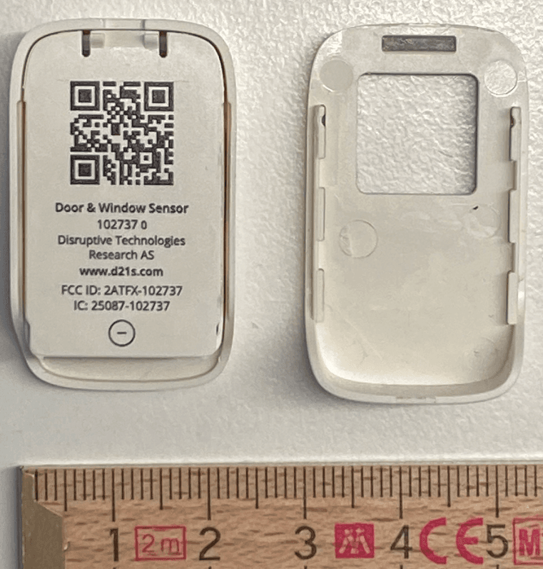
2ATFX-102737
Feb 14, 2024A wireless sensor used to detect if doors and windows are opened or closed.
Equipment Class
DTS - Digital Transmission System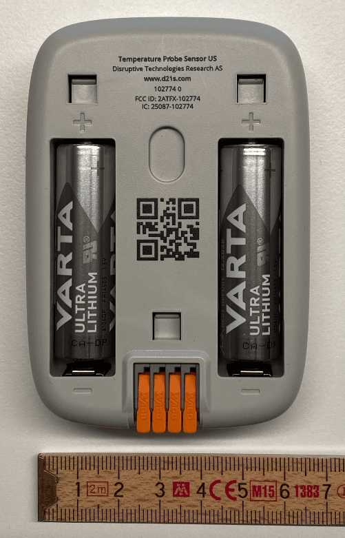
2ATFX-102774
Feb 13, 2024A wireless temperature sensor using an external PT100 temperature sensor element.
Equipment Class
DTS - Digital Transmission System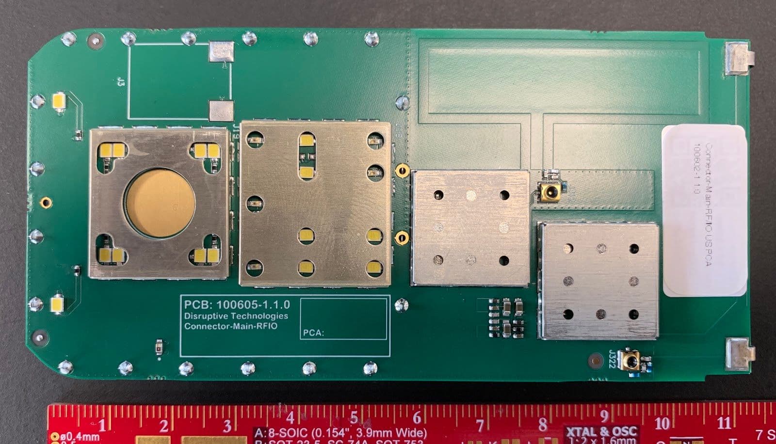
2ATFX-101941
Aug 19, 2020DT-RFIO-Module (US)
Equipment Class
DTS - Digital Transmission System