2ATQIW1Smart Phone
Wings Mobile Telecom SL
Click to zoom
Application Details
- Equipment Class
- DTS - Digital Transmission System
- Date of Grant
- Apr 08, 2020
- Application Purpose
- Original Equipment
- Date of Application
- Apr 08, 2020
- Equipment Note
- Smart Phone
- Frequency Range
- 2412.00000000 - 2462.00000000
- Company
- Wings Mobile Telecom SL
- Country
- Spain
Documents & Files
Document Text
Text extracted from the exhibit documents filed with the FCC. Open a document above to read the original.
Users Manual
Read me first • Please read this manual before operating your mobile phone, and keep it for future reference. • The descriptions in this manual are based on the default settings. • Images and screenshots used in this manual may differ from the actual product. • Available features and additional services may vary by device, software or service provider. • Our company is not liable for performance issues caused by third-party applications. Assembling Unpack Check your product box for the following items. • Mobile phone • User manual • Adapter You can purchase additional accessories from your local retailer. Charge the battery Before using the device for the first time, you must charge the battery. 1. You can charge the device with a travel adapter or by connecting the device to a PC with a USB cable. 2. Battery full icon is shown when finished if your device is off. WARNING Use only original batteries and chargers. Unapproved chargers or cables can cause batteries to explode or damage your device. Install the SIM card You need to insert a SIM card to use the Phone function. To install the SIM card, follow the instructions below. 1. Make sure that the card’s gold contacts face into the device. 2. Push the SIM card into the slot. Install the memory card To store additional multimedia files, you need insert a memory card. 1. Insert a memory card with the gold contacts facing downwards. 2. Push the memory card into the slot. Notice: Our company uses approved industry standards for memory cards, but some brands may not be fully compatible with your device. Getting started • Turn your device on ,rebootand off • To turn on your device, press and hold the power key. • To reboot your device, press and hold the power key, select “reboot” . • To turn off your device, press and hold the power key, select “power off”. Switch to flight mode To use only your device’s non-network services, switch to flight mode. Please follow the instructions below to turn on flight mode: Tap Settings Network & Internet / Advanced / Airplane mode from application list to turn on flight mode. Home screen The home screen has multiple panels. Scroll left or right to the panels on the home screen, you can view indicator icons, widgets, shortcuts to applications, and other items. Task bar The task bar is shown at the top of the screen. It displays commonly used option buttons, battery level indicator, current time and other indicator icons. Indicator icons Notification panel Pull down to open the top of the notification bar to show the 6 users commonly used shortcut switch, support click on the switch, and long press to enter the correspond- ing settings. If you continue to pull down the notification bar to display all the quick switch, fast switch in the lower right corner of page will display a “Edit” button, click to add / delete custom shortcut switch, or drag the sort. Tap icon to activate or deactivate wireless connection features and other settings. Wi-Fi: Activate or deactivate the Wi-Fi connection. Bluetooth: Activate or deactivate the Bluetooth connection. Notifications: Activate or deactivate the notification feature. Flashlight: Activate or deactivate the Flashlight. Auto-rotate screen: Activate or deactivate the auto rotation feature. Battery Saver: Activate or deactivate the Battery Saver. Brightness: Adjust the basic brightness level of the display to lighter or darker. Settings: Access Settings application. Auto rotation If you rotate the device while using some features, the interface will automatically rotate as well. To prevent the interface from rotating, open the notifications panel and select Auto-rotate screen, then tap it to Off. Lock & unlock the screen • Slide to unlock the screen. • To lock the screen manually, press Power key. Customize your device To customize your device according to your preferences, tap Settings from application list or notification panel. Manage applications To manage the applications installed on your device, tap Settings/Apps & notifica- tions. 1. To uninstall an application, select an item and tap UNINSTALL, tap OK to confirm. 2. To stop or change the settings of an application, select an item and tap the option you need. Security You can protect your device and data by setting screen lock or encrypting your mobile phone. Set a screen lock To set a screen lock, tap Settings/Security & location/Screen lock from application list. • None: Deactivate the screen lock. • Swipe: Slide to unlock the screen. • Pattern: Draw a pattern to unlock. Follow the instructions to draw your lock pattern. When prompted, draw the pattern to unlock the screen. • PIN: Enter a numeric PIN to unlock. When prompted, enter the PIN to unlock the screen. • Password: Enter a passcode to unlock. When prompted, enter the pass- code to unlock the screen. Screen time-out Select Settings/Display/Advanced/Sleep from application list, you can set the time before the screen times out and goes into lock mode. ( you have not entered any characters or made other selections). Set up the fingerprint Fingerprint: Want to use your fingerprint to unlock the screen or confirmation of purchase, you need to: 1. set the standby screen lock mode; 2. and add your fingerprint; ATTENTION: In addition to using fingerprint unlock their devices, you can also set the equipment before startup requires the user to unlock pattern, to further protect the equipment. Equipment starts, to answer the phone, receiving a message or notice (including alarm clock).This can be in to protect the data on the equipment after the device is lost or stolen. Display size You can set it Settings/Display/Advanced/Display size Data saver You can set it Settings/Network & Internet/Data usage/Data saver Quick Switch You can switch applications by simply double clicking the “Recents” button Reset mobile phone You can reset system and desktop settings to their original values by the following steps: 1. Select Settings/System/Advanced/Reset options from appli…
Text truncated - open the document above for the full version.
Cover Letter(s)
QA-FR-170-B Wings Mobile Telecom SL ADD: c/Beethoven 15, piso 4 Barcelona Spain TEL: +34658224081 FAX: +34658224081 E-mail:[email protected] FCC Authorization Date: 2020-03-05 FEDERAL COMMUNICATIONS COMMISSION Authorization and Evaluation Division 7435 Oakland Mills Road Columbia, MD 21046 Subject: Agent Authorization To whom it may concern: We ,Wings Mobile Telecom SL, Hereby authorizes Bay Area Compliance Laboratories Corporation to act on its behalf in all matters relating to application for Equipment authorization, including the signing of all documents relating to these matters. All acts carried out by Bay Area Compliance Laboratory Corporation on our behalf shall have the same effect as our own action. We, the undersigned, hereby certify that we are not subject to a denial of federal benefits, that includes FCC benefits, pursuant to Section 5301 of the Anti-Drug Abuse Act of 1988, 21 U.S.C. 862. This authorization is valid until further written notice from the applicant. Sincerely Yours, Client’s signature Antonio Milio Manager
Cover Letter(s)
QA-FR-171-A Wings Mobile Telecom SL ADD: c/Beethoven 15, piso 4 Barcelona Spain TEL: +34658224081 FAX: +34658224081 E-mail:[email protected] FCC Confidential Authorization Date: 2020-03-05 FEDERAL COMMUNICATIONS COMMISSIONS Authorization and Evaluation Division 7435 Oakland Mills Road Columbia, MD 21046 Subject: Confidentiality Request regarding application for certification of FCC ID: 2ATQIW1 In accordance with Sections 0.457 and 0.459 of the Commission’s Rules, (Wings Mobile Telecom SL) hereby requests long-term confidential treatment of information accompanying this application as outlined below: x Block Diagram x Schematics x Operation Description x Parts List/Tune up procedure (for licensed devices) The above materials contain proprietary and confidential information not customarily released to the public. The public disclosure of these materials provides unjustified benefits to its competitors in the market. Sincerely, Signature: Antonio Milio Manager
ID Label/Location Info
Model: W1 SN: WINGSW1000001 IMEI1:351618104423151 IMEI2:351618104423169 Made in China FCC ID: 2ATQIW1
Internal Photos
EXHIBIT C - EUT INTERNAL PHOTOGRAPHS 2/3/4G Antenna Aux Antenna WIFI/BT Antenna
RF Exposure Info
Note: This test report is prepared for the customer shown above and for the device described herein. It may not be duplicated or used in part without prior written consent from Bay Area Compliance Laboratories Corp. (Dongguan). This report must not be used by the customer to claim product certification, approval, or endorsement by A2LA* or any agency of the Federal Government. * This report may contain data that are not covered by the A2LA accreditation and are marked with an asterisk “*”. SAR EVALUATION REPORT For Wings Mobile Telecom SL c/Beethoven 15, piso 4, Barcelona, Spain FCC ID: 2ATQIW1 Report Type: Original Report Product Type: Smart Phone Report Number: RDG200228013-20 Report Date: 2020-03-23 Reviewed By: Rocky Xiao RF Engineer Prepared By: Bay Area Compliance Laboratories Corp. (Dongguan) No.69 Pulongcun, Puxinhu Industry Area, Tangxia, Dongguan, Guangdong, China Tel: +86-769-86858888 Fax: +86-769-86858891 www.baclcorp.com.cn Bay Area Compliance Laboratories Corp. (Dongguan) Report No.: RDG200228013-20 SAR Evaluation Report 2 of 67 Attestation of Test Results EUT Information EUT Description Smart Phone Tested Model W1 FCC ID 2ATQIW1 Serial Number RDG200228013-SA-S1 Test Date 2020-02-29~ 2020-03-03 MODE Max. SAR Level(s) Reported(W/kg) Limit (W/kg) GSM 850 1g Head SAR 0.27 1.6 1g Body SAR 0.69 PCS 1900 1g Head SAR 0.11 1g Body SAR 1.13 WCDMA Band 2 1g Head SAR 0.20 1g Body SAR 1.16 WCDMA Band 5 1g Head SAR 0.18 1g Body SAR 0.22 LTE Band 2 1g Head SAR 0.20 1g Body SAR 1.18 LTE Band 4 1g Head SAR 0.12 1g Body SAR 1.03 LTE Band 7 1g Head SAR 0.05 1g Body SAR 1.04 WLAN 2.4G 1g Head SAR 0.11 1g Body SAR 0.09 Simultaneous 1g Head SAR 0.38 1g Body SAR 1.13 1g Body SAR 1.13 (Hotspot) Applicable Standards FCC 47 CFR part 2.1093 Radiofrequency radiation exposure evaluation: portable devices RF Exposure Procedures: TCB Workshop April 2019 IEEE1528:2013 IEEE Recommended Practice for Determining the Peak Spatial-Average Specific Absorption Rate (SAR) in the Human Head from Wireless Communications Devices: Measurement Techniques IEC 62209-2:2010 Human exposure to radio frequency fields from hand-held and body-mounted wireless communication devices-Human models, instrumentation, and procedures-Part 2: Procedure to determine the specific absorption rate (SAR) for wireless communication devices used in close proximit y to the human body (frequencyrange of 30 MHz to 6 GHz) KDB procedures KDB 447498 D01 General RF Exposure Guidance v06 KDB 648474 D04 Handset SAR v01r03 KDB 865664 D01 SAR Measurement 100 MHz to 6 GHz v01r04 KDB 865664 D02 RF Exposure Reporting v01r02 KDB 941225 D01 3G SAR Procedures v03r01 KDB 941225 D05 SAR for LTE Devices v02r05 KDB 941225 D06 Hotspot Mode v02r01 KDB 248227 D01 802 11 Wi-Fi SAR v02r02 Note: This wireless device has been shown to be capable of compliance for localized specific absorption rate (SAR) for General Population/Uncontrolled Exposure limits specified in FCC 47 CFR part 2.1093 and has been tested in accordance with the measurement procedures specified in IEEE 1528-2013 and RF exposure KDB procedures. The results and statements contained in this report pertain only to the device(s) evaluated. Bay Area Compliance Laboratories Corp. (Dongguan) Report No.: RDG200228013-20 SAR Evaluation Report 3 of 67 TABLE OF CONTENTS DOCUMENT REVISION HISTORY ......................................................................................................................... 4 EUT DESCRIPTION .................................................................................................................................................... 5 TECHNICAL SPECIFICATION ......................................................................................................................................... 5 REFERENCE, STANDARDS, AND GUIDELINES .................................................................................................. 6 SAR LIMITS ................................................................................................................................................................. 7 FACILITIES .................................................................................................................................................................. 8 DESCRIPTION OF TEST SYSTEM .......................................................................................................................... 9 EQUIPMENT LIST AND CALIBRATION ............................................................................................................. 15 EQUIPMENTS LIST & CALIBRATION INFORMATION .................................................................................................... 15 SAR MEASUREMENT SYSTEM VERIFICATION .............................................................................................. 16 LIQUID VERIFICATION ............................................................................................................................................... 16 SYSTEM ACCURACY VERIFICATION ........................................................................................................................... 18 SAR SYSTEM VALIDATION DATA ..................................................................................................................... 19 EUT TEST STRATEGY AND METHODOLOGY ................................................................................................. 25 TEST POSITIONS FOR DEVICE OPERATING NEXT TO A PERSON’S EAR........................................................................ 25 CHEEK/TOUCH POSITION ........................................................................................................................................... 26 EAR/TILT POSITION ................................................................................................................................................... 26 TEST POSITIONS FOR BODY-WORN AND OTHER CONFIGURATIONS ...................…
Text truncated - open the document above for the full version.
RF Exposure Info
PROBE CALIBRATION CERTIFICATES DIPOLE CALIBRATION CERTIFICATES
RF Exposure Info
Report No.: RDG200228013-20 Page 1 of 6 APPENDIX B EUT TEST POSITION PHOTOS Liquid depth ≥ 15cm Phantom: Twin SAM; Type: Twin SAM V5.0; Serial: TP:1412 Report No.: RDG200228013-20 Page 2 of 6 Head Left Cheek Setup Photo Head Left Tilt Setup Photo Report No.: RDG200228013-20 Page 3 of 6 Head Right Cheek Setup Photo Head Right Tilt Setup Photo Report No.: RDG200228013-20 Page 4 of 6 Body (Worn) Back Setup Photo (10mm) Body (Worn) Front Setup Photo (10mm) 10 mm 10 mm Report No.: RDG200228013-20 Page 5 of 6 Body Left Setup Photo (10mm) Body Right Setup Photo (10mm) 10mm 10mm Report No.: RDG200228013-20 Page 6 of 6 Body Bottom Setup Photo (10mm) Body Top Setup Photo (10mm) 10mm 10mm
RF Exposure Info
Report No.: RDG200228013-20 Page 1 of 110 Test Plot 1#:GSM 850_Head Left Cheek _Middle DUT: Smart Phone; Type: W1; Serial: RDG200228013-SA-S1 Communication System: Generic GSM; Frequency: 836.6 MHz;Duty Cycle: 1:8 Medium parameters used: f = 836.6 MHz; σ = 0.894 S/m; ε r = 40.575; ρ = 1000 kg/m 3 ; Phantom section: Left Section DASY5 Configuration: Probe: EX3DV4 - SN7329; ConvF(9.97, 9.97, 9.97) @ 836.6 MHz; Calibrated: 2019/10/22 Sensor-Surface: 1.4mm (Mechanical Surface Detection) Electronics: DAE4 Sn772; Calibrated: 2019/10/6 Phantom: Twin SAM; Type: Twin SAM V5.0; Serial: TP:1412 Measurement SW: DASY52, Version 52.10 (2); SEMCAD X Version 14.6.12 (7470) Area Scan (111x61x1): Interpolated grid: dx=1.500 mm, dy=1.500 mm Maximum value of SAR (interpolated) = 0.263 W/kg Zoom Scan (5x5x7)/Cube 0: Measurement grid: dx=8mm, dy=8mm, dz=5mm Reference Value = 5.556 V/m; Power Drift = 0.07 dB Peak SAR (extrapolated) = 0.293 W/kg SAR(1 g) = 0.226 W/kg; SAR(10 g) = 0.176 W/kg Maximum value of SAR (measured) = 0.268 W/kg 0 dB = 0.268 W/kg = -5.72 dBW/kg Report N Test Plot 2 DUT: Sma Communi c Medium pa Phantom s DASY5 C o Pr Se E P h M Area Sca n Maximum Zoom Sc a Reference Peak SAR SAR(1 g) = Maximum o.: RDG2002 2#: GSM 850 art Phone; Ty cation System arameters use ection: Left S onfiguration: robe: EX3DV ensor-Surface lectronics: DA hantom: Twin Measurement S n (111x61x1): value of SA R an (5x5x7)/Cu Value = 10.62 (extrapolated = 0.160 W/kg value of SAR 0 dB = 0. 28013-20 0_Head Left T ype: W1; Ser m: Generic GSM d: f = 836.6 M ection V4 - SN7329; C e: 1.4mm (Mec AE4 Sn772;Ca n SAM; Type: SW: DASY52 Interpolated g R (interpolated ube 0:Measure 2 V/m; Power d) = 0.207 W/k g; SAR(10 g) R (measured) = .191 W/kg = - Tilt_Middle rial: RDG200 M; Frequency MHz; σ = 0.89 ConvF(9.97, 9 chanical Surfa alibrated: 201 Tw i n S A M V , Version 52.1 grid: dx=1.500 d) = 0.194 W/k ement grid: dx r Drift = -0.17 kg = 0.124 W/k g = 0.191 W/kg -7.19 dBW/kg 0228013-SA-S y: 836.6 MHz; 94 S/m; ε r = 40 9.97, 9.97) @ ace Detection 9/10/6 V5.0; Serial: T 10 (2); SEMCA 0 mm, dy=1.5 kg x=8mm, dy=8 7 dB g g g S1 ;Duty Cycle: 1 0.575; ρ = 100 836.6 MHz; C ) TP:1412 AD X Version 500 mm 8mm, dz=5mm 1:8 00 kg/m 3 ; Calibrated: 20 n 14.6.12 (747 m 19/10/22; 70) Page 2 of 110 Report N Test Plot 3 DUT: Sma Communi c Medium pa Phantom s DASY5 C o Pr Se E P h M Area Sca n Maximum Zoom Sc a Reference Peak SAR SAR(1 g) = Maximum o.: RDG2002 3#: GSM 850 art Phone; Ty cation System arameters use ection: Right onfiguration: robe: EX3DV ensor-Surface lectronics: DA hantom: Twin Measurement S n (111x61x1): value of SA R an (6x6x7)/Cu Value = 4.768 (extrapolated = 0.264 W/kg value of SAR 0 dB = 0. 28013-20 0_Head Right ype: W1; Ser m: Generic GSM d: f = 836.6 M Section V4 - SN7329; C e: 1.4mm (Mec AE4 Sn772;Ca n SAM; Type: SW: DASY52 Interpolated g R (interpolated ube 0:Measure 8 V/m; Power d) = 0.343 W/k g; SAR(10 g) R (measured) = .315 W/kg = - t Cheek_Mid rial: RDG200 M; Frequency MHz; σ = 0.89 ConvF(9.97, 9 chanical Surfa alibrated: 201 Tw i n S A M V , Version 52.1 grid: dx=1.500 d) = 0.317 W/k ement grid: dx r Drift = 0.09 kg = 0.206 W/k g = 0.315 W/kg -5.02 dBW/kg dle 0228013-SA-S y: 836.6 MHz; 94 S/m; ε r = 40 9.97, 9.97) @ ace Detection 9/10/6 V5.0; Serial: T 10 (2); SEMCA 0 mm, dy=1.5 kg x=8mm, dy=8 dB g g g S1 ;Duty Cycle: 1 0.575; ρ = 100 836.6 MHz; C ) TP:1412 AD X Version 500 mm 8mm, dz=5mm 1:8 00 kg/m 3 ; Calibrated: 20 n 14.6.12 (747 m 19/10/22; 70) Page 3 of 110 Report N Test Plot 4 DUT: Sma Communi c Medium pa Phantom s DASY5 C o Pr Se E P h M Area Sca n Maximum Zoom Sc a Reference Peak SAR SAR(1 g) = Maximum o.: RDG2002 4#: GSM 850 art Phone; Ty cation System arameters use ection: Right onfiguration: robe: EX3DV ensor-Surface lectronics: DA hantom: Twin Measurement S n (111x61x1): value of SA R an (5x5x7)/Cu Value = 7.483 (extrapolated = 0.136 W/kg value of SAR 0 dB = 0. 28013-20 0_Head Right ype: W1; Ser m: Generic GSM d: f = 836.6 M Section V4 - SN7329; C e: 1.4mm (Mec AE4 Sn772;Ca n SAM; Type: SW: DASY52 Interpolated g R (interpolated ube 0:Measure 3 V/m; Power d) = 0.172 W/k g; SAR(10 g) R (measured) = .159 W/kg = - t Tilt_Middle rial: RDG200 M; Frequency MHz; σ = 0.89 ConvF(9.97, 9 chanical Surfa alibrated: 201 Tw i n S A M V , Version 52.1 grid: dx=1.500 d) = 0.159 W/k ement grid: dx r Drift = 0.15 kg = 0.108 W/k g = 0.159 W/kg -7.99 dBW/kg e 0228013-SA-S y: 836.6 MHz; 94 S/m; ε r = 40 9.97, 9.97) @ ace Detection 9/10/6 V5.0; Serial: T 10 (2); SEMCA 0 mm, dy=1.5 kg x=8mm, dy=8 dB g g g S1 ;Duty Cycle: 1 0.575; ρ = 100 836.6 MHz; C ) TP:1412 AD X Version 500 mm 8mm, dz=5mm 1:8 00 kg/m 3 ; Calibrated: 20 n 14.6.12 (747 m 19/10/22; 70) Page 4 of 110 Report N Test Plot 5 DUT: Sma Communi c Medium pa Phantom s DASY5 C o Pr Se E P h M Area Sca n Maximum Zoom Sc a Reference Peak SAR SAR(1 g) = Maximum o.: RDG2002 5#: GSM 850 art Phone; Ty cation System arameters use ection: Flat S e onfiguration: robe: EX3DV ensor-Surface lectronics: DA hantom: Twin Measurement S n (61x121x1): value of SA R an (5x5x7)/Cu Value = 18.60 (extrapolated = 0.342 W/kg value of SAR 0 dB = 0. 28013-20 0_Body Worn ype: W1; Ser m: Generic GSM d: f = 836.6 M ection V4 - SN7329; C e: 1.4mm (Mec AE4 Sn772;Ca n SAM; Type: SW: DASY52 Interpolated g R (interpolated ube 0:Measure 0 V/m; Power d) = 0.458 W/k g; SAR(10 g) R (measured) = .418 W/kg = - n Back_Midd rial: RDG200 M; Frequency MHz; σ = 0.89 ConvF(9.97, 9 chanical Surfa alibrated: 201 Tw i n S A M V , Version 52.1 grid: dx=1.500 d) = 0.415 W/k ement grid: dx r Drift = 0.11 kg = 0.260 W/k g = 0.418 W/kg -3.79 dBW/kg dle 0228013-SA-S y: 836.6 MHz; 94 S/m; ε r = 40 9.97, 9.97) @ ace Detection 9/10/6 V5.0; Serial: T 10 (2); SEMCA 0 mm, dy=1.5 kg x=8mm, dy=8 dB g g g S1 ;Duty Cycle: 1 0.575; ρ = 100 836.6 MHz; C ) TP:1412 AD X Version 500 mm 8mm, dz=5mm 1:8 00 kg/m 3 ; Calibrated: 20 n 14.6.12 (747 m 19/10/22; 70) Page 5 of 110 Report N Test Plot 6 DUT:…
Text truncated - open the document above for the full version.
Test Report
FCC PART 15.247 TEST REPORT For Wings Mobile Telecom SL c/Beethoven 15, piso 4, Barcelona, Spain Report Type: Original Report Product Name: Smart Phone Re port Number: RDG200228013-00A Re port Date: 2020-03-21 Reviewed By: Ivan Cao Assistant Manager Test Laboratory: Bay Area Compliance Laboratories Corp. (Dongguan) No.69 Pulongcun, Puxinhu Industry Area, Tangxia, Dongguan, Guangdong, China Tel: +86-769-86858888 Fax: +86-769-86858891 www.baclcorp.com.cn FCC ID: 2ATQIW1 Bay Area Compliance Laboratories Corp. (Dongguan) Report No.: RDG200228013-00A Page 2 of 56 TABLE OF CONTENTS GENERAL INFORMATION ....................................................................................................................................... 4 PRODUCT DESCRIPTION FOR EQUIPMENT UNDER TEST (EUT) ..................................................................................... 4 OBJECTIVE ................................................................................................................................................................... 4 RELATED SUBMITTAL(S)/GRANT(S) ............................................................................................................................. 4 TEST METHODOLOGY .................................................................................................................................................. 4 MEASUREMENT UNCERTAINTY .................................................................................................................................... 5 TEST FACILITY ............................................................................................................................................................. 5 DECLARATIONS ............................................................................................................................................................ 5 SYSTEM TEST CONFIGURATION .......................................................................................................................... 6 DESCRIPTION OF TEST CONFIGURATION ...................................................................................................................... 6 EUT EXERCISE SOFTWARE .......................................................................................................................................... 7 EQUIPMENT MODIFICATIONS ..................................................................................................................................... 10 SUPPORT CABLE LIST AND DETAILS .......................................................................................................................... 10 BLOCK DIAGRAM OF TEST SETUP .............................................................................................................................. 11 SUMMARY OF TEST RESULTS ............................................................................................................................. 12 FCC §15.247 (i) & §1.1310 & §2.1093- RF EXPOSURE .......................................................................................... 13 APPLICABLE STANDARD ............................................................................................................................................ 13 FCC §15.203 - ANTENNA REQUIREMENT ........................................................................................................... 14 APPLICABLE STANDARD ............................................................................................................................................ 14 ANTENNA CONNECTOR CONSTRUCTION .................................................................................................................... 14 FCC §15.207 (a) – AC LINE CONDUCTED EMISSIONS ..................................................................................... 15 APPLICABLE STANDARD ............................................................................................................................................ 15 EUT SETUP ................................................................................................................................................................ 15 EMI TEST RECEIVER SETUP ....................................................................................................................................... 15 TEST PROCEDURE ...................................................................................................................................................... 16 CORRECTED AMPLITUDE & MARGIN CALCULATION ................................................................................................. 16 TEST EQUIPMENT LIST AND DETAILS ......................................................................................................................... 16 TEST DATA ................................................................................................................................................................ 16 FCC §15.209, §15.205 & §15.247(d) - SPURIOUS EMISSIONS ............................................................................. 19 APPLICABLE STANDARD ............................................................................................................................................ 19 EUT SETUP ................................................................................................................................................................ 19 EMI TEST RECEIVER & SPECTRUM ANALYZER SETUP .............................................................................................. 20 TEST PROCEDURE ...................................................................................................................................................... 20 CORRECTED AMPLITUDE & MARGIN CALCULATION ................................................................................................. 20 TEST EQUIPMENT LIST AND DETAILS .............…
Text truncated - open the document above for the full version.
Test Setup Photos
EXHIBIT D - TEST SETUP PHOTOGRAPHS Conducted Emissions Front View Conducted Emissions Side View Radiated Emission Below 1GHz View Radiated Emission Above 1GHz View
Contact Information
Applicant
Antonio Milio(Manager)
Test Firm
Bay Area Compliance Laboratories Corp.(Dongguan)David Zhang
[email protected]0086 0769 86858888
Technical Specifications
| # | Rule Parts | Frequency Range | Power Output |
|---|---|---|---|
| 2 | 15C | 2.41 GHz - 2.46 GHz | 97.00 mW |
Other Applications from Wings Mobile Telecom SL
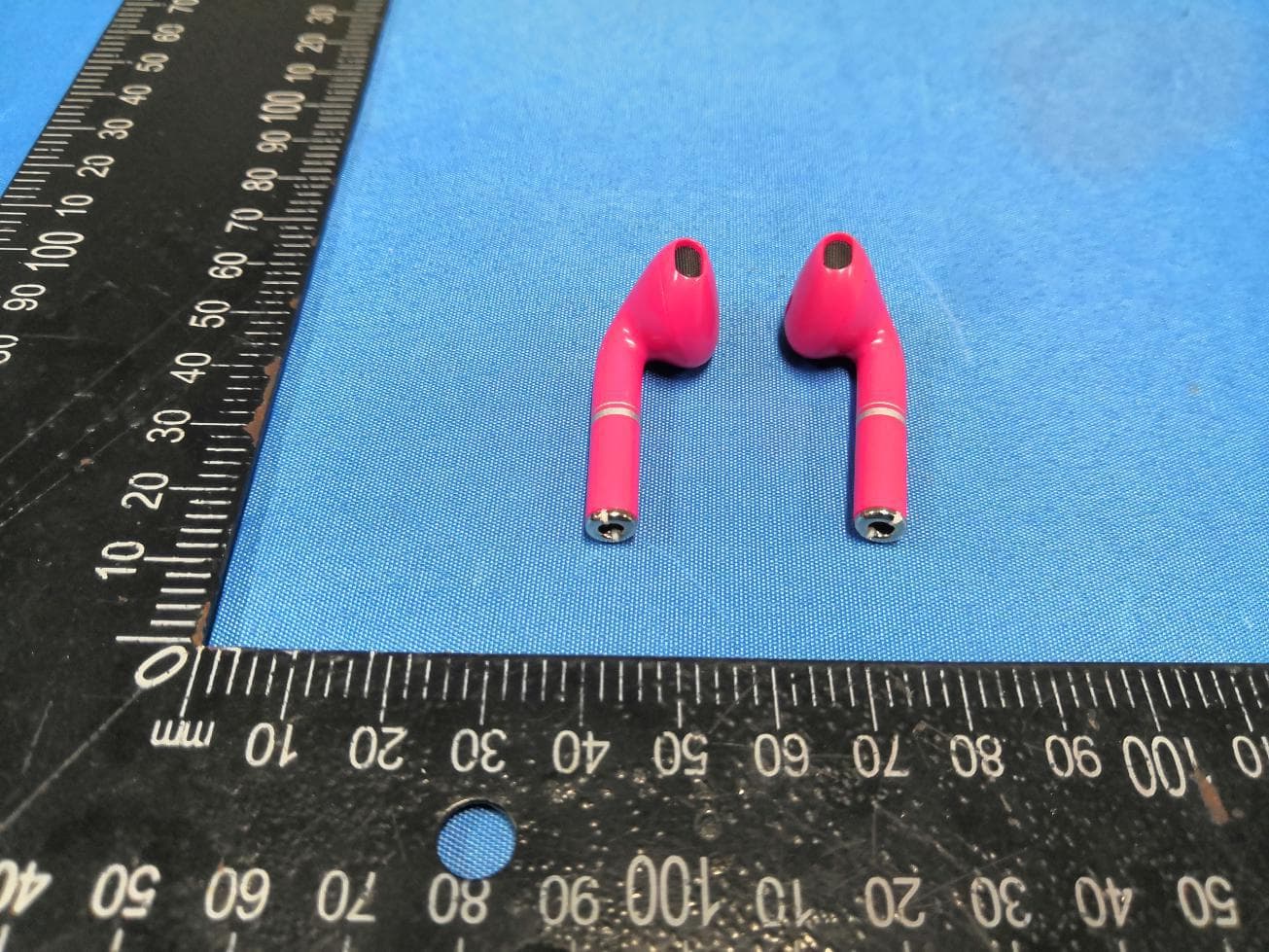
2ATQI-HS
Jan 26, 2021Headphones
Equipment Class
DXX - Part 15 Low Power Communication Device Transmitter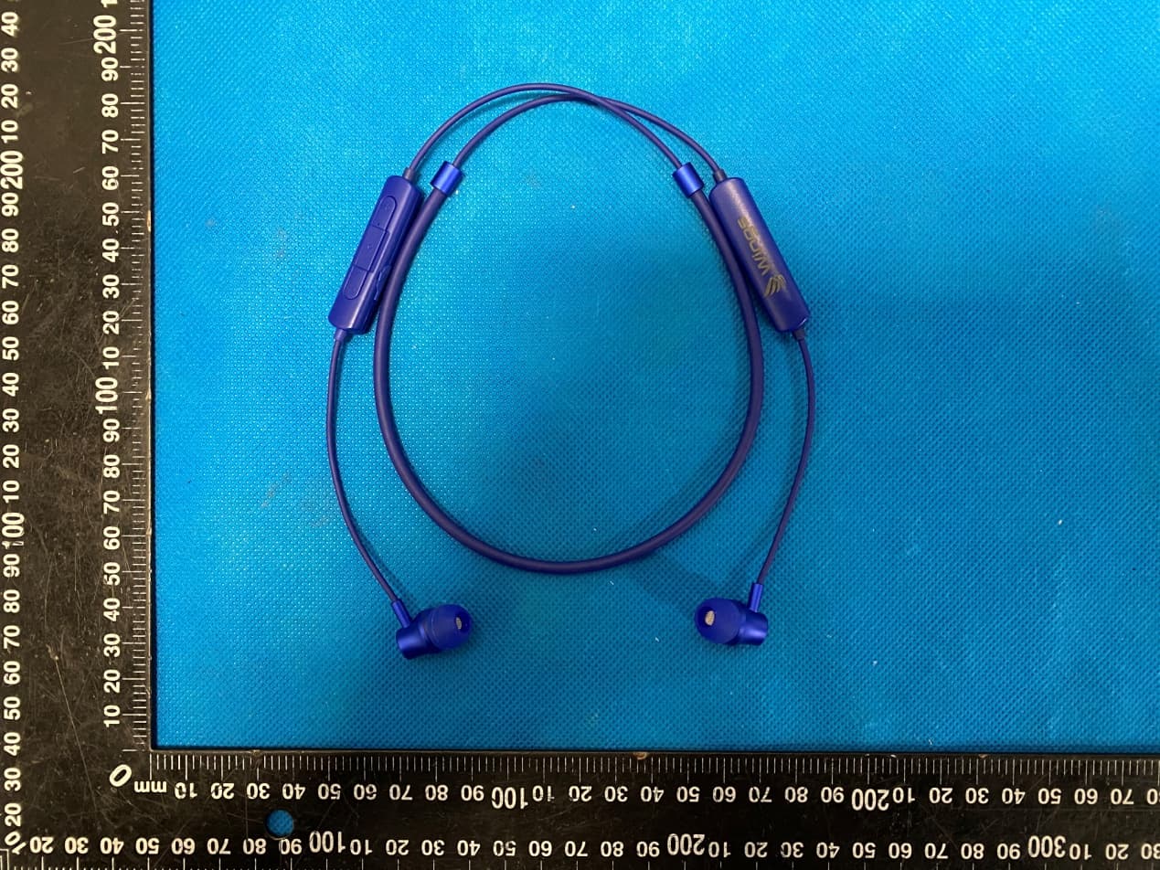
2ATQI-WSE01
Jan 12, 2021Bluetooth earphone
Equipment Class
DSS - Part 15 Spread Spectrum Transmitter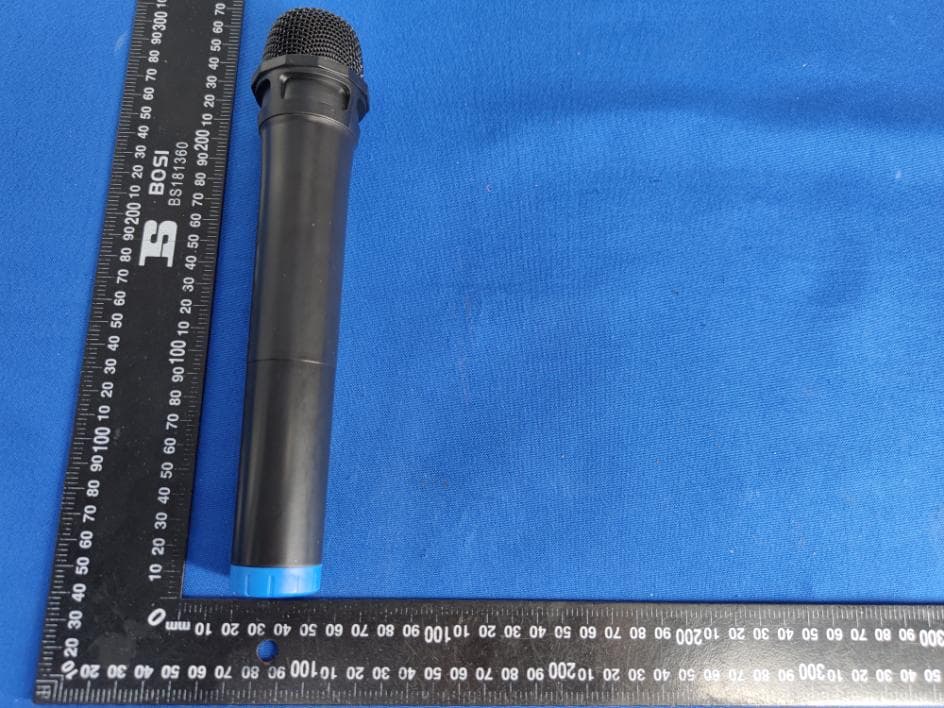
2ATQI-HI-FICLASSIC
Nov 03, 20202.1 CH SPEAKER
Equipment Class
DWM - Part 15 Wireless Microphone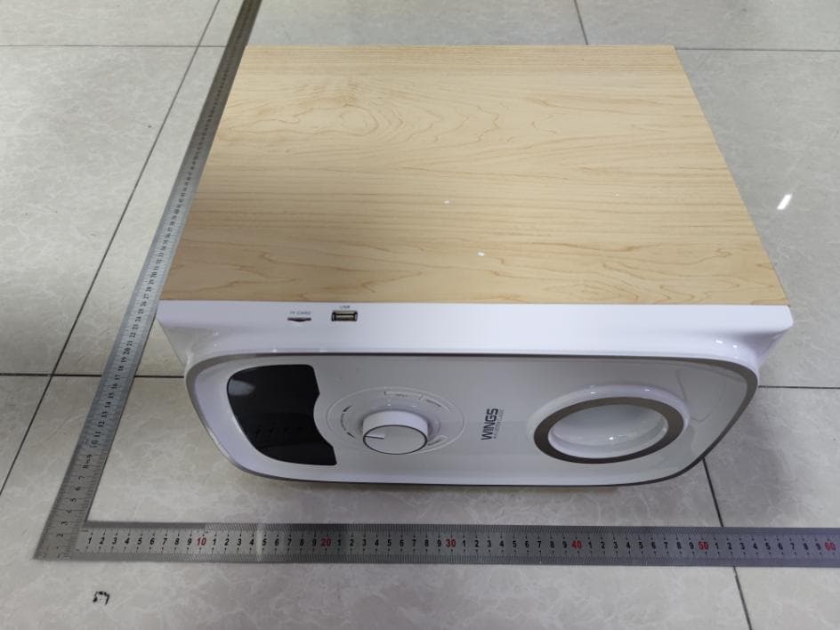
2ATQI-CLASSIC
Oct 27, 20202.1 CH SPEAKER
Equipment Class
DSS - Part 15 Spread Spectrum Transmitter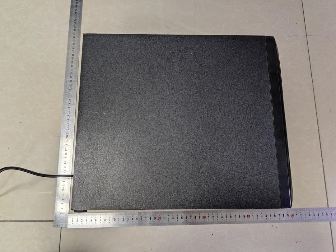
2ATQI-TECH
Oct 27, 20202.1 CH SPEAKER
Equipment Class
DSS - Part 15 Spread Spectrum Transmitter