2ATV8TRIMLIGHTVNLED Controller
Shenzhen Sperll Optoelectronic Technology Co., Ltd.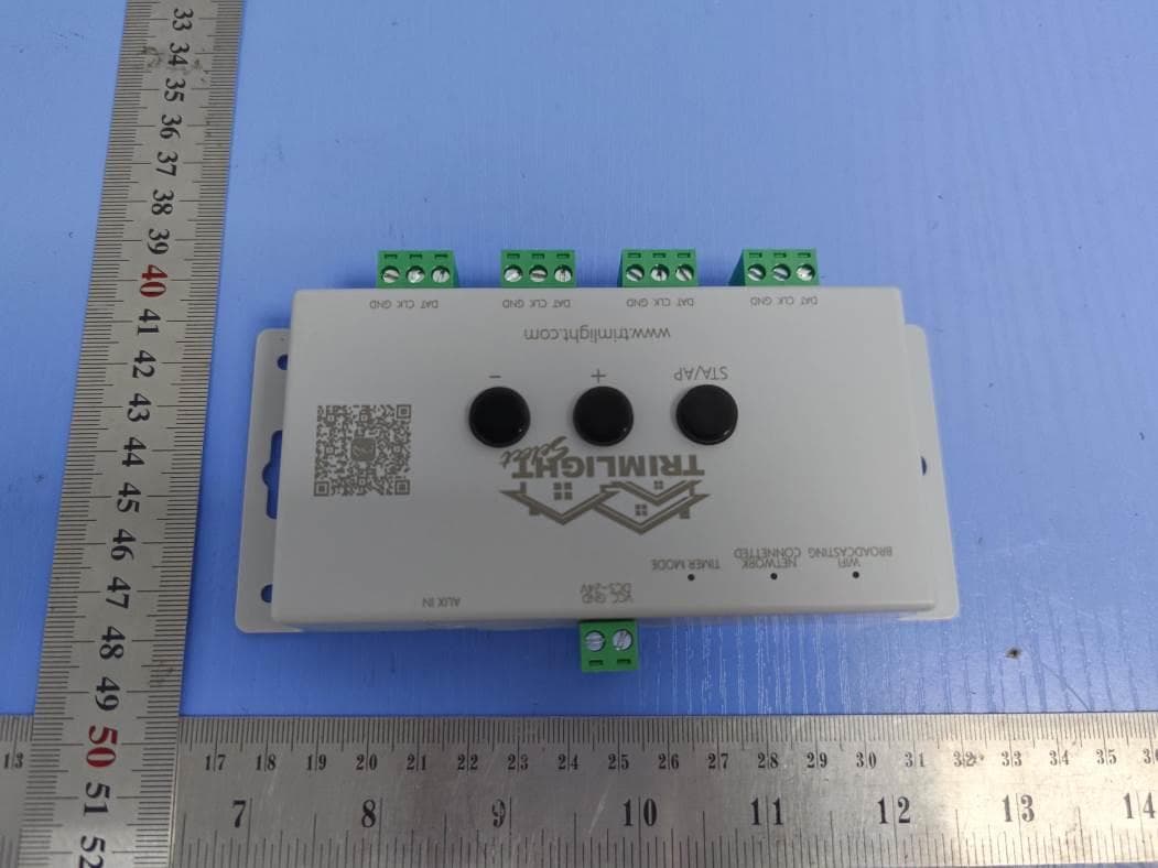
Click to zoom
Application Details
- Equipment Class
- DTS - Digital Transmission System
- Date of Grant
- Aug 11, 2021
- Application Purpose
- Original Equipment
- Date of Application
- Aug 11, 2021
- Equipment Note
- LED Controller
- Frequency Range
- 2412.00000000 - 2462.00000000
- Country
- China
Documents & Files
Document Text
Text extracted from the exhibit documents filed with the FCC. Open a document above to read the original.
Users Manual
Important Information: Trimlight should never be worked on while the power is on. Please disconnect the wire from the outlet whenever you are going to change a light bulb or move wiring. Trimlight is a low voltage system and safe but it is recommended that no other lighting system should be connected into the system. Do not connect any other devices to the Trimlight system without consent from a licensed electrician or a Trimlight representative. CONGRATULATIONS!! You have just purchased a new Trimlight permanent lighting system. The following guidelines will help you get to know your system better and understand how to operate and maintain your new Trimlight system. Understanding the WiFi System and Application Your new Trimlight Select PLUS system can be downloaded to multiple devices but it is important to remember that the system can only be connected and controlled from one phone or device at a time. You can download the application through your device’s application search function. Simply go to your Apps search bar and download the app titled: Trimlight Your system can be controlled via the wifi network that is internally broadcasting or be connected to your local home or business wifi network. 180 Default Patterns More on page 3. Individual Scroll Using the side arrows allow the user to incrementally scroll through each pattern throughout the dial. Pre-Set Programs There are 180 default programs within this dial. Simply drag a finger around to see the many different default modes. The outside ring with differing colors shows separation of different categories. The name or description of the pattern is located on the top of the screen Brightness and Speed These icons will allow the user to adjust the brightness of the diodes or speed of the movement for any pattern that is found within this page. Categories Simple categories for easy access to favorite default patterns. Simply touch any of the categories and the dial will automatically place the dial to the first pattern in the category. Add to Library Use this button to save one of the default patterns to an event or favorite for future reference. Calendar and Favorites More on Page 4. Return to Controller List This icon allows the user to return to the main controller page to access more controllers. Using the Trimlight App! The following 3 pages explain each section of the application for simple understanding of how to control your Trimlight Select Plus system Sequencing Spacing This slider bar allows a user to alter the quantity of sequencing in the chosen pattern. Reverse Direction This icon allows any of the patterns to reverse direction. Music Function More on Page 4. Settings Access for Controller Settings Creating an ACCOUNT For any online capable features and functionality, Follow the prompts on the app to create an account. Pairing to a local WIFI Network The following items must be considered prior to starting this process: 1. The location of the Trimlight Controller must have a very strong signal to the local wifi network. Check the signal bars on the device at the location of the controller to ensure it’s strength. IF A POOR SIGNAL EXISTS at the controller location, there are 2 options; A. Use a Wifi repeater on your network between the router and the Trimlight Controller. B. Choose to operate the controller on the BLUE light setting by not connecting it to the local network. Choosing option B will not allow the controller to receive periodic updates, Use Grouping feature, or Remote Access 2. If you have a mesh network or multiple access points on your network. The controller will be connected to the closest one only. When the app is establishing a connection to each connected controller, the closer in proximity the mobile device is to the correct access point, the faster the connection will be made. Once this process has been completed, the user will no longer need to use the Trimlight wifi signal to connect to the control- lers. These steps are one way for connecting: More pairing to a router tips found at TRIMLIGHT.COM/troubleshooting Step #1 Ensure the device is connected to the local WIFI router network with adequate internet connectivity. Step #2 Press the “ADD DEVICE” button in the upper right hand corner. It is shown as a “+”. [email protected] Step #3 Follow the prompts on the device to properly pair the controller to the internet. It is recommended to start with the MANUAL MODE. Step #1 Push “Sign Up” and enter your password Step #2 Retrieve code from your email Step #3 Enter your password for the account. Settings The following settings are for programming the lights to operate properly in the most functional way. If an authorized dealer or installer set this up, please do not adjust any of the settings without proper guidance. Pixel Assignment This area will allow all the lights on each output to be assigned their address. Outputs are based on how the system was installed originally. These settings will be required to be accurate for the custom program page for any form of zoning programs. Remove Device Scolling down will allow a user to remove a controller from the account More pairing to a router tips found at TRIMLIGHT.COM/troubleshooting Version This is the current Firmware software on the controller, periodically checking for newest updates is recommended. Must be connected to the local network for this feature. IC Type Standard IC types with a Trimlight system are UCS1903. This should be the default mode RGB Order Most Trimlight systems are designed as an RGB order. Only in rare occurrences will this be different. Please ensure this is always RGB Controller Name This is the name of the controller that is currently connected. This name can be changed by accessing this box. The following settings may be needing adjustment if there are more than one controller on a system or on an account. Manual / Timer / Off Toggle switch allows the following: Off = Bypasses all timers and schedule and shuts off the light…
Text truncated - open the document above for the full version.
Cover Letter(s)
Shenzhen Sperll Optoelectronic Technology Co., Ltd. Add: 4th Floor, Building 3, NO.1059 Songbai Road, Nanshan District Shenzhen China Date: 2021-8-11 FCC ID: 2ATV8TRIMLIGHTVN Dear Sir/Madam, We, Shenzhen Sperll Optoelectronic Technology Co., Ltd. Hereby declares the following statement for Federal Communications Commission, PCB board, circuit, structure and internal of these model(s) are the same, Only model number is different for these model: Product name: LED Controller Model no.: TrimlightV2, TrimlightV1, TrimlightV3,TrimlightV4, TrimlightV5, TrimlightV6 Sincerely, Name/Title: Derek Xie/Engineer Company: Shenzhen Sperll Optoelectronic Technology Co., Ltd. Address: 4th Floor, Building 3, NO.1059 Songbai Road, Nanshan District Shenzhen China Phone: 18823863369 Fax: 0755-89378380 E-Mail: [email protected]
Cover Letter(s)
CONFIDENTIALITY REQUEST for Certification Service in USA Federal Communication Commission Equipment Authorization Division, Application Processing Branch 7435 Oakland Mills Road Columbia, MD 21046 Date:<2021-8-11> Pursuant to Paragraphs §0.457 and 0.459 of the Commission’s Rules (47 C.F.R.) and Section §552(b)(4) of the Freedom of Information Act, we requests confidentiality for the following products: FCC ID Model name 2ATV8TRIMLIGHTVN TrimlightV2 For the product stated above, we request that the following information be held confidential; Exhibits Long-Term Confidentiality Short-Term Confidentiality Short-Term Confidentiality Days External Photos Internal Photos Block Diagram Schematics Test Setup Photos User’s Manual Parts List Tune Up Operational Descriptions The long-term confidentiality exhibits contain our trade secrets and proprietary information that could be of benefit to our competitors. The short-term confidentiality on the basis of ensuring that business sensitive information remains confidential until the actual marketing of our new device. If you have any questions, please feel free to contact me at the address shown below. Sincerely, Name/Title: Derek Xie/Engineer Company: Shenzhen Sperll Optoelectronic Technology Co., Ltd. Address: 4th Floor, Building 3, NO.1059 Songbai Road, Nanshan District Shenzhen China Phone: 18823863369 Fax: 0755-89378380 E-Mail: [email protected]
Cover Letter(s)
Shenzhen Sperll Optoelectronic Technology Co., Ltd. 4th Floor, Building 3, NO.1059 Songbai Road, Nanshan District Shenzhen China Date: 2021-8-11 FCC ID: 2ATV8TRIMLIGHTVN Model Number: TrimlightV2 To: Federal Communications Commission Authorization and Evaluation Division 7435 Oakland Mills Road Columbia, MD To Whom It May Concern, We, Shenzhen Sperll Optoelectronic Technology Co., Ltd. , declare that this EUT (FCC ID: 2ATV8TRIMLIGHTVN ) doesn’t have Ad Hoc mode function on “non-US/Canada frequencies”. In addition. The frequency selection feature is disabled by firmware for devices marked to the US/Canada. For DTS part of this device, only channels 1-11 will be used in North America, Country code selection is disabled. Should you have any questions or comments regarding this matter, please have my best attention. Sincerely, Name/Title: Derek Xie/Engineer Company: Shenzhen Sperll Optoelectronic Technology Co., Ltd. Address: 4th Floor, Building 3, NO.1059 Songbai Road, Nanshan District Shenzhen China Phone: 18823863369 Fax: 0755-89378380 E-Mail: [email protected]
Cover Letter(s)
Shenzhen Sperll Optoelectronic Technology Co., Ltd. 4th Floor, Building 3, NO.1059 Songbai Road, Nanshan District Shenzhen China Federal Communications Commission Authorization and Evaluation Division Equipment Authorization Branch 7435 Oakland Mills Road Columbia, MD 21046 2021-8-11 To whom it may concern: We, Shenzhen Sperll Optoelectronic Technology Co., Ltd. the undersigned, hereby authorize Eurofins Product Service GmbH to act on our behalf in all matters relating to applications for equipment authorization FCC ID: 2ATV8TRIMLIGHTVN including the signing of all documents related to these matters. Any and all acts carried out by Eurofins Product Service GmbH on our behalf shall have the same effect as acts of our own. We also hereby certify that no party to this application is subject to a denial of benefits, including FCC benefits, pursuant to Section 5301 of the Anti-Drug Abuse Act of 1988, 21 U.S.C. 862. Sincerely, Name/Title: Derek Xie/Engineer Company: Shenzhen Sperll Optoelectronic Technology Co., Ltd. Address: 4th Floor, Building 3, NO.1059 Songbai Road, Nanshan District Shenzhen China Phone: 18823863369 Fax: 0755-89378380 E-Mail: [email protected]
External Photos
Shenzhen LCS Compliance Testing Laboratory Ltd. FCC ID: 2ATV8TRIMLIGHTVN This report shall not be reproduced except in full, without the written approval of Shenzhen LCS Compliance Testing Laboratory Ltd. Page 1 of 3 External Photos of the EUT Fig.1 Fig.2 Shenzhen LCS Compliance Testing Laboratory Ltd. FCC ID: 2ATV8TRIMLIGHTVN This report shall not be reproduced except in full, without the written approval of Shenzhen LCS Compliance Testing Laboratory Ltd. Page 2 of 3 Fig.3 Fig.4 Shenzhen LCS Compliance Testing Laboratory Ltd. FCC ID: 2ATV8TRIMLIGHTVN This report shall not be reproduced except in full, without the written approval of Shenzhen LCS Compliance Testing Laboratory Ltd. Page 3 of 3 Fig.5 Fig.6
ID Label/Location Info
Shenzhen LCS Compliance Testing Laboratory Ltd. FCC ID: 2ATV8TRIMLIGHTVN _____________________________________________________________________________________________________ This report shall not be reproduced except in full, without the written approval of Shenzhen LCS Compliance Testing Laboratory Ltd.. Page 1 of 1 LABEL AND LOCATION (Size: L4.5m x 3.0cm) Label Location LED Controller Model No.: TrimlightV2 FCC ID: 2ATV8TRIMLIGHTVN Caution:This device complies with part 15 of the FCC Rules. Operation is subject to the following two conditions: (1) This device may not cause harmful interference, and (2) this device must accept any interference received, including interference that may cause undesired operation.
Internal Photos
Shenzhen LCS Compliance Testing Laboratory Ltd. FCC ID: 2ATV8TRIMLIGHTVN This report shall not be reproduced except in full, without the written approval of Shenzhen LCS Compliance Testing Laboratory Ltd. Page 1 of 2 Internal Photos of the EUT Fig.1 Fig.2 Shenzhen LCS Compliance Testing Laboratory Ltd. FCC ID: 2ATV8TRIMLIGHTVN This report shall not be reproduced except in full, without the written approval of Shenzhen LCS Compliance Testing Laboratory Ltd. Page 2 of 2 Fig.3 Fig.4 BT WIFI Antenna
RF Exposure Info
Shenzhen LCS Compliance Testing Laboratory Ltd. FCC ID: 2ATV8TRIMLIGHTVN This report shall not be reproduced except in full, without the written approval of Shenzhen LCS Compliance Testing Laboratory Ltd. Page 1 of 5 FCC RF Exposure Evaluation 1. Product Information FCC ID 2ATV8TRIMLIGHTVN Product name LED Controller Model number TrimlightV2 Additional Model TrimlightV1, TrimlightV3, TrimlightV4, TrimlightV5, TrimlightV6 Model Declaration PCB board, structure and internal of these model(s) are the same, So no additional models were tested. Power supply DC 5~24V Modulation Type GFSK for Bluetooth V5.0(DTS) IEEE 802.11b: DSSS(CCK,DQPSK,DBPSK); IEEE 802.11g/n: OFDM(64QAM, 16QAM, QPSK, BPSK) Antenna Type PCB Antenna Antenna Gain 0dBi(Max.) Hardware version V1.1 Software version V1.1 FCC Operation frequency 2402MHz ~ 2480MHz 2412MHz-2462MHz Exposure category General population/uncontrolled environment EUT Type Production Unit Device Type Mobile Devices 2. Evaluation Method Systems operating under the provisions of FCC 47 CFR section shall be operated in a manner that ensures that the public is not exposed to radio frequency energy level in excess of the Commission’s guidelines. In accordance with 47 CFR FCC Part 2 Subpart J, section 2.1091 this device has been defined as mobile device whereby a distance of 0.2m normally can be maintained between the user and the device, and below RF Permissible Exposure limit shall comply with. In accordance with KDB447498D01 for Simultaneous transmission MPE test exclusion applies when the sum of the MPE ratios for all simultaneous transmitting antennas incorporated in a host device, based on the calculated/estimated, numerically modelled or measured field strengths or power density, is ≤ 1.0. The MPE ratio of each antenna is determined at the minimum test separation distance required by the operating configurations and exposure conditions of the host device, according to the ratio of field strengths or power density to MPE limit, at the test frequency. Either the maximum peak or spatially averaged results from measurements or numerical simulations may be used to determine the MPE ratios. Spatial averaging does not apply when MPE is estimated using simple calculations based on far-field plane-wave equivalent conditions. The antenna installation and operating requirements for the host device must meet the minimum test separation distances required by all antennas, in both standalone and simultaneous transmission operations, to satisfy compliance. Shenzhen LCS Compliance Testing Laboratory Ltd. FCC ID: 2ATV8TRIMLIGHTVN This report shall not be reproduced except in full, without the written approval of Shenzhen LCS Compliance Testing Laboratory Ltd. Page 2 of 5 3. Limit 3. 1 Refer Evaluation Method ANSI C95.1–1999: IEEE Standard for Safety Levels with Respect to Human Exposure to Radio Frequency Electromagnetic Fields, 3 kHz to 300 GHz. FCC KDB publication 447498 D01 General 1 RF Exposure Guidance v06: Mobile and Portable Devices RF Exposure Procedures and Equipment Authorization Policies. FCC CFR 47 part1 1.1310: Radiofrequency radiation exposure limits. FCC CFR 47 part2 2.1091: Radiofrequency radiation exposure evaluation: mobile devices 3. 2 Limit Limits for Maximum Permissible Exposure (MPE)/Controlled Exposure Frequency Range(MHz) Electric Field Strength(V/m) Magnetic Field Strength(A/m) Power Density (mW/cm²) Averaging Time (minute) Limits for Occupational/Controlled Exposure 0.3 – 3.0 3.0 – 30 30 – 300 300 – 1500 1500 – 100,000 614 1842/f 61.4 / / 1.63 4.89/f 0.163 / / (100) * (900/f 2 )* 1.0 f/300 5 6 6 6 6 6 Limits for Maximum Permissible Exposure (MPE)/Uncontrolled Exposure Frequency Range(MHz) Electric Field Strength(V/m) Magnetic Field Strength(A/m) Power Density (mW/cm²) Averaging Time (minute) Limits for Occupational/Controlled Exposure 0.3 – 3.0 3.0 – 30 30 – 300 300 – 1500 1500 – 100,000 614 824/f 27.5 / / 1.63 2.19/f 0.073 / / (100) * (180/f 2 )* 0.2 f/1500 1.0 30 30 30 30 30 F=frequency in MHz *=Plane-wave equivalent power density 4. MPE Calculation Method Predication of MPE limit at a given distance Equation from page 18 of OET Bulletin 65, Edition 97-01 S=PG/4πR² Where: S=power density P=power input to antenna G=power gain of the antenna in the direction of interest relative to an isotropic radiator R=distance to the center of radiation of the antenna 5. Antenna Information Artemis Antenna can only use antennas certificated as follows provided by manufacturer; Internal Identification Antenna type and antenna number Operate frequency band Maximum antenna gain Note Antenna PCB Antenna 2400MHz ~ 2500MHz 0dBi BT/WIFI Antenna Shenzhen LCS Compliance Testing Laboratory Ltd. FCC ID: 2ATV8TRIMLIGHTVN This report shall not be reproduced except in full, without the written approval of Shenzhen LCS Compliance Testing Laboratory Ltd. Page 3 of 5 6. Conducted Power < BT LE Max Conducted Power > Mode Channel Frequency(MHz) Max Conducted Power (dBm) GFSK 0 2402 1.533 19 2440 1.621 39 2480 1.916 <2.4GWLAN Max Conducted Power > Mode Channel Frequency(MHz) Max Conducted Power (dBm) IEEE 802.11b 1 2412 15.99 6 2437 15.67 11 2462 15.37 IEEE 802.11g 1 2412 12.04 6 2437 13.72 11 2462 13.35 IEEE 802.11n HT20 1 2412 12.02 6 2437 13.69 11 2462 13.28 Shenzhen LCS Compliance Testing Laboratory Ltd. FCC ID: 2ATV8TRIMLIGHTVN This report shall not be reproduced except in full, without the written approval of Shenzhen LCS Compliance Testing Laboratory Ltd. Page 4 of 5 7. Manufacturing Tolerance <BT LE> GFSK (Peak) Channel Channel 0 Channel 19 Channel 39 Target (dBm) 1.0 1.0 1.0 Tolerance ±(dB) 1.0 1.0 1.0 <2.4G WIFI> 11B (Peak) Channel Channel 1 Channel 6 Channel 11 Target (dBm) 16.0 16.0 15.0 Tolerance ±(dB) 1.0 1.0 1.0 11G (Peak) Channel Channel 1 Channel 6 Channel 11 Target (dBm) 12.0 14.0 13.0 Tolerance ±(dB) 1.0 1.0 1.0 11N20SISO (Peak) Channel Channel 1 Channel 6 Channel 11 Target (dBm) 12.0 14.0 13.0 Tolerance ±(dB) 1.0 1.0 1.0 Shenzhen LCS Compliance Testing Labor…
Text truncated - open the document above for the full version.
Test Report
Shenzhen LCS Compliance Testing Laboratory Ltd. FCC ID: 2ATV8TRIMLIGHTVN Report No.: LCS210623100AEA Page 1 of 17 Appendix A RF Test Data for BT V5.0(Conducted Measurement) Product Name: LED Controller Trade Mark: SPERLL Test Model: TrimlightV2 Environmental Conditions Temperature: 24.6 C Relative Humidity: 54.1% ATM Pressure: 100.0 kPa Test Engineer: Jay Li Supervised by: Li Huan A.1 DutyCycle Test Result TestMode Antenna Channel ON Time [ms] Period [ms] X DC [%] xFactor Limit Verdict BLE_1M Ant1 2402 0.38 0.62 0.6129 61.29 2.13 --- PASS 2440 0.38 0.62 0.6129 61.29 2.13 --- PASS 2480 0.38 0.62 0.6129 61.29 2.13 --- PASS Test Graphs BLE_1M_Ant1_2402 Shenzhen LCS Compliance Testing Laboratory Ltd. FCC ID: 2ATV8TRIMLIGHTVN Report No.: LCS210623100AEA Page 2 of 17 BLE_1M_Ant1_2440 BLE_1M_Ant1_2480 Shenzhen LCS Compliance Testing Laboratory Ltd. FCC ID: 2ATV8TRIMLIGHTVN Report No.: LCS210623100AEA Page 3 of 17 A.2 Maximum Peak Conducted Output Power Mode Channel Conduct Peak Power[dBm] Limit [dBm] Verdict BT LE LCH 1.533 30 PASS BT LE MCH 1.621 30 PASS BT LE HCH 1.916 30 PASS Test Graphs LCH MCH Shenzhen LCS Compliance Testing Laboratory Ltd. FCC ID: 2ATV8TRIMLIGHTVN Report No.: LCS210623100AEA Page 4 of 17 HCH Shenzhen LCS Compliance Testing Laboratory Ltd. FCC ID: 2ATV8TRIMLIGHTVN Report No.: LCS210623100AEA Page 5 of 17 A.3 Maximum power spectral density Test Result TestMode Antenna Channel Result[dBm/3-100kHz] Limit[dBm/3kHz] Verdict BLE_1M Ant1 2402 -7.27 ≤8 PASS 2440 -6.06 ≤8 PASS 2480 -7.26 ≤8 PASS Test Graphs BLE_1M_Ant1_2402 BLE_1M_Ant1_2440 BLE_1M_Ant1_2480 Shenzhen LCS Compliance Testing Laboratory Ltd. FCC ID: 2ATV8TRIMLIGHTVN Report No.: LCS210623100AEA Page 6 of 17 Shenzhen LCS Compliance Testing Laboratory Ltd. FCC ID: 2ATV8TRIMLIGHTVN Report No.: LCS210623100AEA Page 7 of 17 A.4 6dB Bandwidth Test Result TestMode Channel DTS BW [MHz] FL[MHz] FH[MHz] Limit[MHz] Verdict BLE_1M 2402 0.668 2401.668 2402.336 0.5 PASS 2440 0.676 2439.668 2440.344 0.5 PASS 2480 0.684 2479.656 2480.340 0.5 PASS Test Graphs BLE_1M_Ant1_2402 BLE_1M_Ant1_2440 BLE_1M_Ant1_2480 Shenzhen LCS Compliance Testing Laboratory Ltd. FCC ID: 2ATV8TRIMLIGHTVN Report No.: LCS210623100AEA Page 8 of 17 Shenzhen LCS Compliance Testing Laboratory Ltd. FCC ID: 2ATV8TRIMLIGHTVN Report No.: LCS210623100AEA Page 9 of 17 A.5 Conducted SpuriousEmission Test Result TestMode Antenna Channel FreqRange [MHz] RefLevel [dBm] Result[dBm] Limit[dBm] Verdict BLE_1M Ant1 2402 Reference 2.10 2.10 --- PASS 30~1000 2.10 -59.15 ≤-17.9 PASS 1000~26500 2.10 -47.72 ≤-17.9 PASS 2440 Reference 2.82 2.82 --- PASS 30~1000 2.82 -61.4 ≤-17.18 PASS 1000~26500 2.82 -46.94 ≤-17.18 PASS 2480 Reference 1.99 1.99 --- PASS 30~1000 1.99 -61.07 ≤-18.01 PASS 1000~26500 1.99 -46.91 ≤-18.01 PASS Shenzhen LCS Compliance Testing Laboratory Ltd. FCC ID: 2ATV8TRIMLIGHTVN Report No.: LCS210623100AEA Page 10 of 17 Test Graphs BLE_1M_Ant1_2402_0~Reference BLE_1M_Ant1_2402_30~1000 BLE_1M_Ant1_2402_1000~26500 Shenzhen LCS Compliance Testing Laboratory Ltd. FCC ID: 2ATV8TRIMLIGHTVN Report No.: LCS210623100AEA Page 11 of 17 BLE_1M_Ant1_2440_0~Reference BLE_1M_Ant1_2440_30~1000 Shenzhen LCS Compliance Testing Laboratory Ltd. FCC ID: 2ATV8TRIMLIGHTVN Report No.: LCS210623100AEA Page 12 of 17 BLE_1M_Ant1_2440_1000~26500 BLE_1M_Ant1_2480_0~Reference BLE_1M_Ant1_2480_30~1000 Shenzhen LCS Compliance Testing Laboratory Ltd. FCC ID: 2ATV8TRIMLIGHTVN Report No.: LCS210623100AEA Page 13 of 17 BLE_1M_Ant1_2480_1000~26500 Shenzhen LCS Compliance Testing Laboratory Ltd. FCC ID: 2ATV8TRIMLIGHTVN Report No.: LCS210623100AEA Page 14 of 17 A.6 Band-edge for RF Conducted Emissions Test Result TestMode Antenna ChName Channel RefLevel[dBm] Result[dBm] Limit[dBm] Verdict BLE_1M Ant1 Low 2402 2.10 -49.89 ≤-17.9 PASS High 2480 2.25 -49.11 ≤-17.75 PASS Test Graphs BLE_1M_Ant1_Low_2402 BLE_1M_Ant1_High_2480 Shenzhen LCS Compliance Testing Laboratory Ltd. FCC ID: 2ATV8TRIMLIGHTVN Report No.: LCS210623100AEA Page 15 of 17 A.7 EmissionsinRestrictedBands Test Result TestMode Antenna ChName Channel Detector Freq. [MHz] Result [dBm] Limit [dBm] Verdict BLE_1M Ant1 Low 2402 AV 2310.000 -48.46 ≤-41.20 PASS AV 2386.100 -47.49 ≤-41.20 PASS AV 2390.000 -47.89 ≤-41.20 PASS Peak 2310.000 -42.17 ≤-21.20 PASS Peak 2375.180 -38.47 ≤-21.20 PASS Peak 2390.000 -41.94 ≤-21.20 PASS High 2480 AV 2483.500 -46.93 ≤-41.20 PASS AV 2483.600 -46.87 ≤-41.20 PASS AV 2500.000 -47.5 ≤-41.20 PASS Peak 2483.500 -41.02 ≤-21.20 PASS Peak 2497.520 -37.61 ≤-21.20 PASS Peak 2500.000 -42.24 ≤-21.20 PASS Note: 1. The Antenna Gain is compensated in the graph. 2. The limit in dBm for average detector is conversion from 54dBuV/m, according to 15.209(a). The limit in dBm for peak detector is 20dB above the limit of average detector in dBm. Shenzhen LCS Compliance Testing Laboratory Ltd. FCC ID: 2ATV8TRIMLIGHTVN Report No.: LCS210623100AEA Page 16 of 17 Test Graphs BLE_1M_Ant1_Low_2402_AV BLE_1M_Ant1_Low_2402_Peak BLE_1M_Ant1_High_2480_AV Shenzhen LCS Compliance Testing Laboratory Ltd. FCC ID: 2ATV8TRIMLIGHTVN Report No.: LCS210623100AEA Page 17 of 17 BLE_1M_Ant1_High_2480_Peak
Test Report
Shenzhen LCS Compliance Testing Laboratory Ltd. FCC ID: 2ATV8TRIMLIGHTVN Report No.: LCS210623100AEB Page 1 of 36 Appendix B RF Test Data for 2.4G WIFI (Conducted Measurement) Product Name: LED Controller Trade Mark: SPERLL Test Model: TrimlightV2 Environmental Conditions Temperature: 24.6 C Relative Humidity: 54.1% ATM Pressure: 100.0 kPa Test Engineer: Carl Fu Supervised by: Li Huan Shenzhen LCS Compliance Testing Laboratory Ltd. FCC ID: 2ATV8TRIMLIGHTVN Report No.: LCS210623100AEB Page 2 of 36 B.1 Duty Cycle Test Result TestMode Antenna Channel Transmission Duration [ms] Transmission Period [ms] Duty Cycle [%] Limit Verdict 11B Ant1 2412 8.39 8.42 99.64 --- PASS 2437 8.38 8.41 99.64 --- PASS 2462 8.39 8.42 99.64 --- PASS 11G Ant1 2412 1.39 1.43 97.20 --- PASS 2437 1.39 1.43 97.20 --- PASS 2462 1.39 1.43 97.20 --- PASS 11N20SISO Ant1 2412 1.30 1.34 97.01 --- PASS 2437 1.30 1.34 97.01 --- PASS 2462 1.30 1.34 97.01 --- PASS Test Graphs 11B_Ant1_2412 11B_Ant1_2437 Shenzhen LCS Compliance Testing Laboratory Ltd. FCC ID: 2ATV8TRIMLIGHTVN Report No.: LCS210623100AEB Page 3 of 36 11B_Ant1_2462 11G_Ant1_2412 Shenzhen LCS Compliance Testing Laboratory Ltd. FCC ID: 2ATV8TRIMLIGHTVN Report No.: LCS210623100AEB Page 4 of 36 11G_Ant1_2437 11G_Ant1_2462 11N20SISO_Ant1_2412 Shenzhen LCS Compliance Testing Laboratory Ltd. FCC ID: 2ATV8TRIMLIGHTVN Report No.: LCS210623100AEB Page 5 of 36 11N20SISO_Ant1_2437 11N20SISO_Ant1_2462 Shenzhen LCS Compliance Testing Laboratory Ltd. FCC ID: 2ATV8TRIMLIGHTVN Report No.: LCS210623100AEB Page 6 of 36 B.2 Maximum Peak Conducted Output Power Test Result TestMode Antenna Channel Result[dBm] Limit[dBm] Verdict 11B Ant1 2412 15.99 ≤30 PASS 2437 15.67 ≤30 PASS 2462 15.37 ≤30 PASS 11G Ant1 2412 12.04 ≤30 PASS 2437 13.72 ≤30 PASS 2462 13.35 ≤30 PASS 11N20SISO Ant1 2412 12.02 ≤30 PASS 2437 13.69 ≤30 PASS 2462 13.28 ≤30 PASS Shenzhen LCS Compliance Testing Laboratory Ltd. FCC ID: 2ATV8TRIMLIGHTVN Report No.: LCS210623100AEB Page 7 of 36 B.3 Maximum power spectral density Test Result Test Mode Channel Result [dBm/10kHz] Convert Factor Result [dBm/3KHz] Limit [dBm/3kHz] Verdict 11B 2412 -10.37 -5.23 -15.60 ≤8 PASS 2437 -11.02 -5.23 -16.25 ≤8 PASS 2462 -11.08 -5.23 -16.31 ≤8 PASS 11G 2412 -15.94 -5.23 -21.17 ≤8 PASS 2437 -14.17 -5.23 -19.40 ≤8 PASS 2462 -14.53 -5.23 -19.76 ≤8 PASS 11N20SISO 2412 -16.03 -5.23 -21.26 ≤8 PASS 2437 -14.17 -5.23 -19.40 ≤8 PASS 2462 -14.76 -5.23 -19.99 ≤8 PASS ***Note: The Convert Factor = 10*log(3KHz/10KHz) = -5.23 Test Graphs 11B_Ant1_2412 11B_Ant1_2437 Shenzhen LCS Compliance Testing Laboratory Ltd. FCC ID: 2ATV8TRIMLIGHTVN Report No.: LCS210623100AEB Page 8 of 36 11B_Ant1_2462 11G_Ant1_2412 Shenzhen LCS Compliance Testing Laboratory Ltd. FCC ID: 2ATV8TRIMLIGHTVN Report No.: LCS210623100AEB Page 9 of 36 11G_Ant1_2437 11G_Ant1_2462 11N20SISO_Ant1_2412 Shenzhen LCS Compliance Testing Laboratory Ltd. FCC ID: 2ATV8TRIMLIGHTVN Report No.: LCS210623100AEB Page 10 of 36 11N20SISO_Ant1_2437 11N20SISO_Ant1_2462 Shenzhen LCS Compliance Testing Laboratory Ltd. FCC ID: 2ATV8TRIMLIGHTVN Report No.: LCS210623100AEB Page 11 of 36 B.4 6dB Bandwidth Test Result TestMode Antenna Channel DTS BW [MHz] FL[MHz] FH[MHz] Limit[MHz] Verdict 11B Ant1 2412 9.640 2407.400 2417.040 0.5 PASS 2437 10.080 2431.960 2442.040 0.5 PASS 2462 9.600 2456.960 2466.560 0.5 PASS 11G Ant1 2412 15.480 2404.080 2419.560 0.5 PASS 2437 15.720 2429.440 2445.160 0.5 PASS 2462 13.240 2453.800 2467.040 0.5 PASS 11N20SISO Ant1 2412 16.160 2404.400 2420.560 0.5 PASS 2437 16.400 2429.440 2445.840 0.5 PASS 2462 16.320 2453.200 2469.520 0.5 PASS Test Graphs 11B_Ant1_2412 11B_Ant1_2437 Shenzhen LCS Compliance Testing Laboratory Ltd. FCC ID: 2ATV8TRIMLIGHTVN Report No.: LCS210623100AEB Page 12 of 36 11B_Ant1_2462 11G_Ant1_2412 Shenzhen LCS Compliance Testing Laboratory Ltd. FCC ID: 2ATV8TRIMLIGHTVN Report No.: LCS210623100AEB Page 13 of 36 11G_Ant1_2437 11G_Ant1_2462 11N20SISO_Ant1_2412 Shenzhen LCS Compliance Testing Laboratory Ltd. FCC ID: 2ATV8TRIMLIGHTVN Report No.: LCS210623100AEB Page 14 of 36 11N20SISO_Ant1_2437 11N20SISO_Ant1_2462 Shenzhen LCS Compliance Testing Laboratory Ltd. FCC ID: 2ATV8TRIMLIGHTVN Report No.: LCS210623100AEB Page 15 of 36 B.5 Conducted Spurious Emission Test Result TestMode Antenna Channel FreqRange [Mhz] RefLevel [dBm] Result [dBm] Limit [dBm] Verdict 11B Ant1 2412 Reference 6.26 6.26 --- PASS 30~1000 6.26 -61.2 ≤-13.74 PASS 1000~26500 6.26 -46.87 ≤-13.74 PASS 2437 Reference 6.78 6.78 --- PASS 30~1000 6.78 -61.97 ≤-13.22 PASS 1000~26500 6.78 -47.65 ≤-13.22 PASS 2462 Reference 6.18 6.18 --- PASS 30~1000 6.18 -61.39 ≤-13.82 PASS 1000~26500 6.18 -47.61 ≤-13.82 PASS 11G Ant1 2412 Reference 0.25 0.25 --- PASS 30~1000 0.25 -61.72 ≤-19.75 PASS 1000~26500 0.25 -46.68 ≤-19.75 PASS 2437 Reference 4.25 4.25 --- PASS 30~1000 4.25 -61.3 ≤-15.75 PASS 1000~26500 4.25 -46.93 ≤-15.75 PASS 2462 Reference 2.58 2.58 --- PASS 30~1000 2.58 -61.55 ≤-17.42 PASS 1000~26500 2.58 -47.63 ≤-17.42 PASS 11N20SISO Ant1 2412 Reference 2.03 2.03 --- PASS 30~1000 2.03 -62.01 ≤-17.97 PASS 1000~26500 2.03 -46.54 ≤-17.97 PASS 2437 Reference 3.03 3.03 --- PASS 30~1000 3.03 -61.6 ≤-16.97 PASS 1000~26500 3.03 -47.07 ≤-16.97 PASS 2462 Reference 3.20 3.20 --- PASS 30~1000 3.20 -61.22 ≤-16.8 PASS 1000~26500 3.20 -47.44 ≤-16.8 PASS Shenzhen LCS Compliance Testing Laboratory Ltd. FCC ID: 2ATV8TRIMLIGHTVN Report No.: LCS210623100AEB Page 16 of 36 Test Graphs 11B_Ant1_2412_0~Reference 11B_Ant1_2412_30~1000 11B_Ant1_2412_1000~26500 Shenzhen LCS Compliance Testing Laboratory Ltd. FCC ID: 2ATV8TRIMLIGHTVN Report No.: LCS210623100AEB Page 17 of 36 11B_Ant1_2437_0~Reference 11B_Ant1_2437_30~1000 Shenzhen LCS Compliance Testing Laboratory Ltd. FCC ID: 2ATV8TRIMLIGHTVN Report No.: LCS210623100AEB Page 18 of 36 11B_Ant1_2437_1000~26500 11B_Ant1_2462_0~Reference 11B_Ant1_2462_30~1000 Shenzhen LCS Compliance Testing Laboratory Ltd. FCC ID: 2ATV8TRIMLIGHTVN Report No.: LCS210623100AEB Page 19 of 36 11B_Ant1_2462_1000~26500 11G_An…
Text truncated - open the document above for the full version.
Test Report
Shenzhen LCS Compliance Testing Laboratory Ltd. FCC ID: 2ATV8TRIMLIGHTVN Report No.: LCS210623100AEA This report shall not be reproduced except in full, without the written approval of Shenzhen LCS Compliance Testing Laboratory Ltd. Page 1 of 32 FCC TEST REPORT For Shenzhen Sperll Optoelectronic Technology Co., Ltd. LED Controller Test Model: TrimlightV2 Additional Model No.: TrimlightV1, TrimlightV3, TrimlightV4, TrimlightV5, TrimlightV6 Prepared for : Shenzhen Spe…
Text truncated - open the document above for the full version.
Contact Information
Applicant
Derek Xie
Test Firm
Shenzhen LCS Compliance Testing Laboratory Ltd.Gavin Liang
Technical Specifications
| # | Rule Parts | Frequency Range | Power Output |
|---|---|---|---|
| 2 | 15C | 2.41 GHz - 2.46 GHz | 39.70 mW |
Other Applications from Shenzhen Sperll Optoelectronic Technology Co., Ltd.
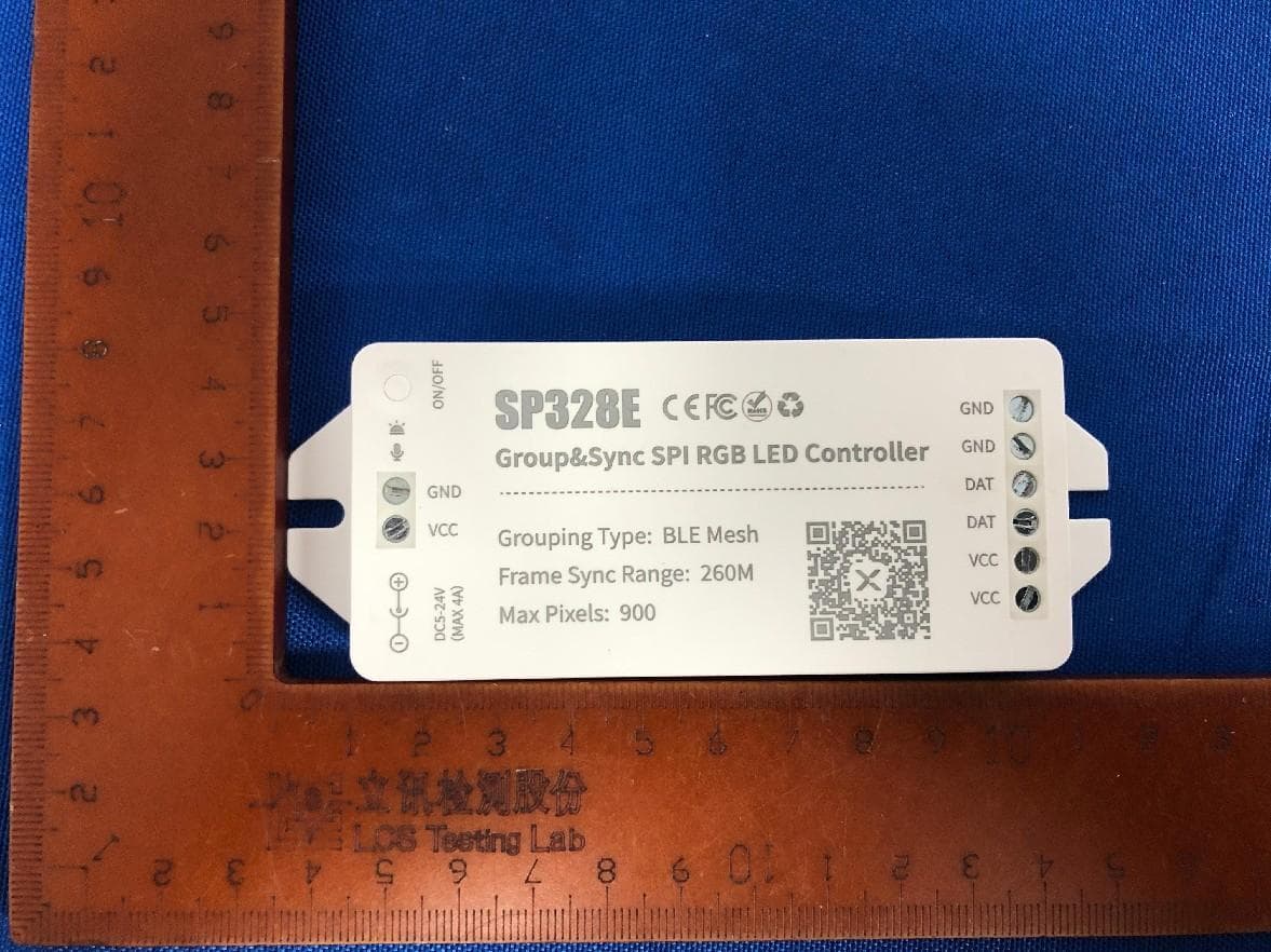
2ATV8SP32XE
Nov 28, 2024LED Controller
Equipment Class
DTS - Digital Transmission System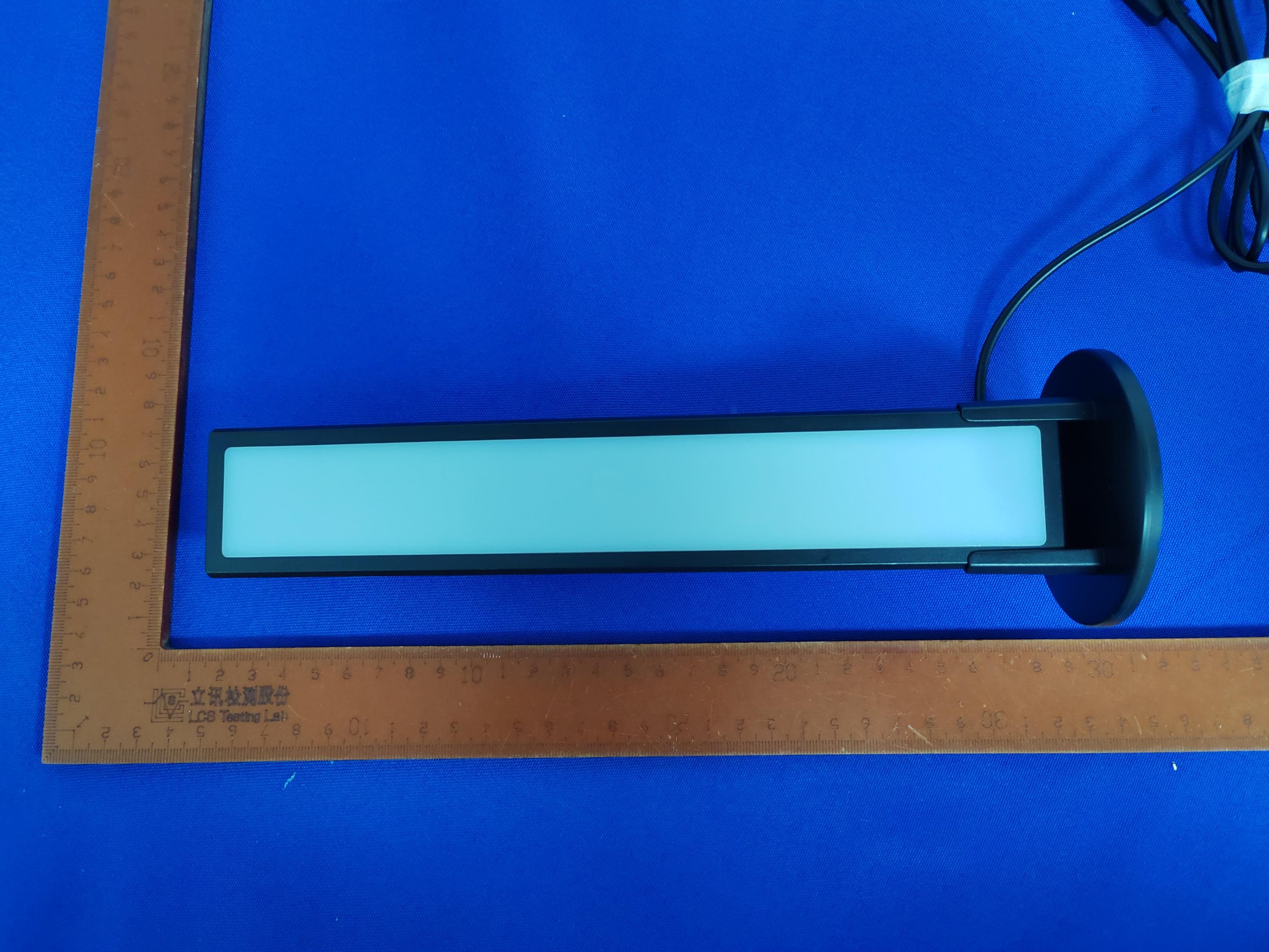
2ATV8DYNAMIC
Aug 12, 2024DynamicBar
Equipment Class
DSS - Part 15 Spread Spectrum Transmitter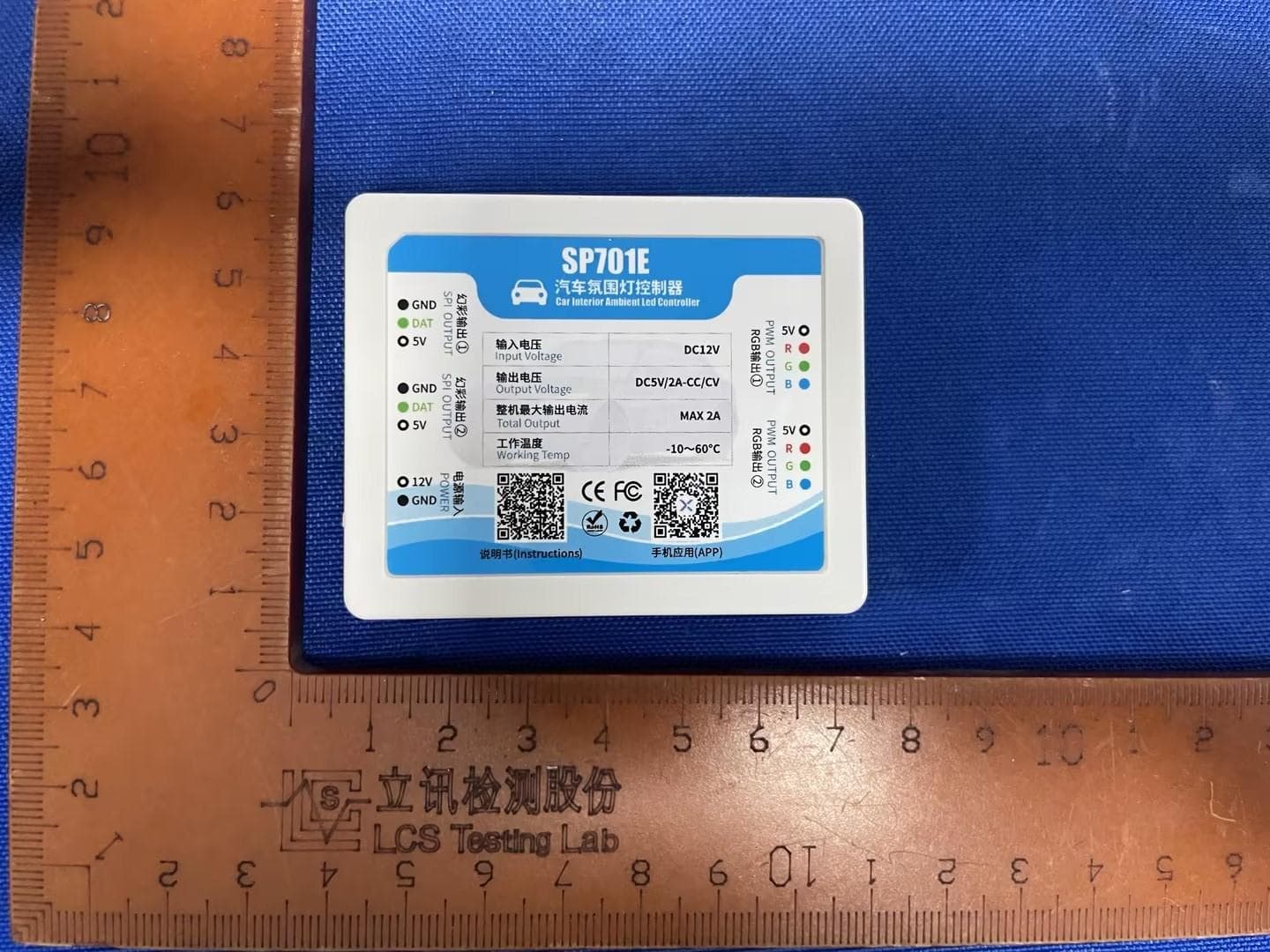
2ATV8SP70XE
Apr 01, 2024LED Controller
Equipment Class
DTS - Digital Transmission System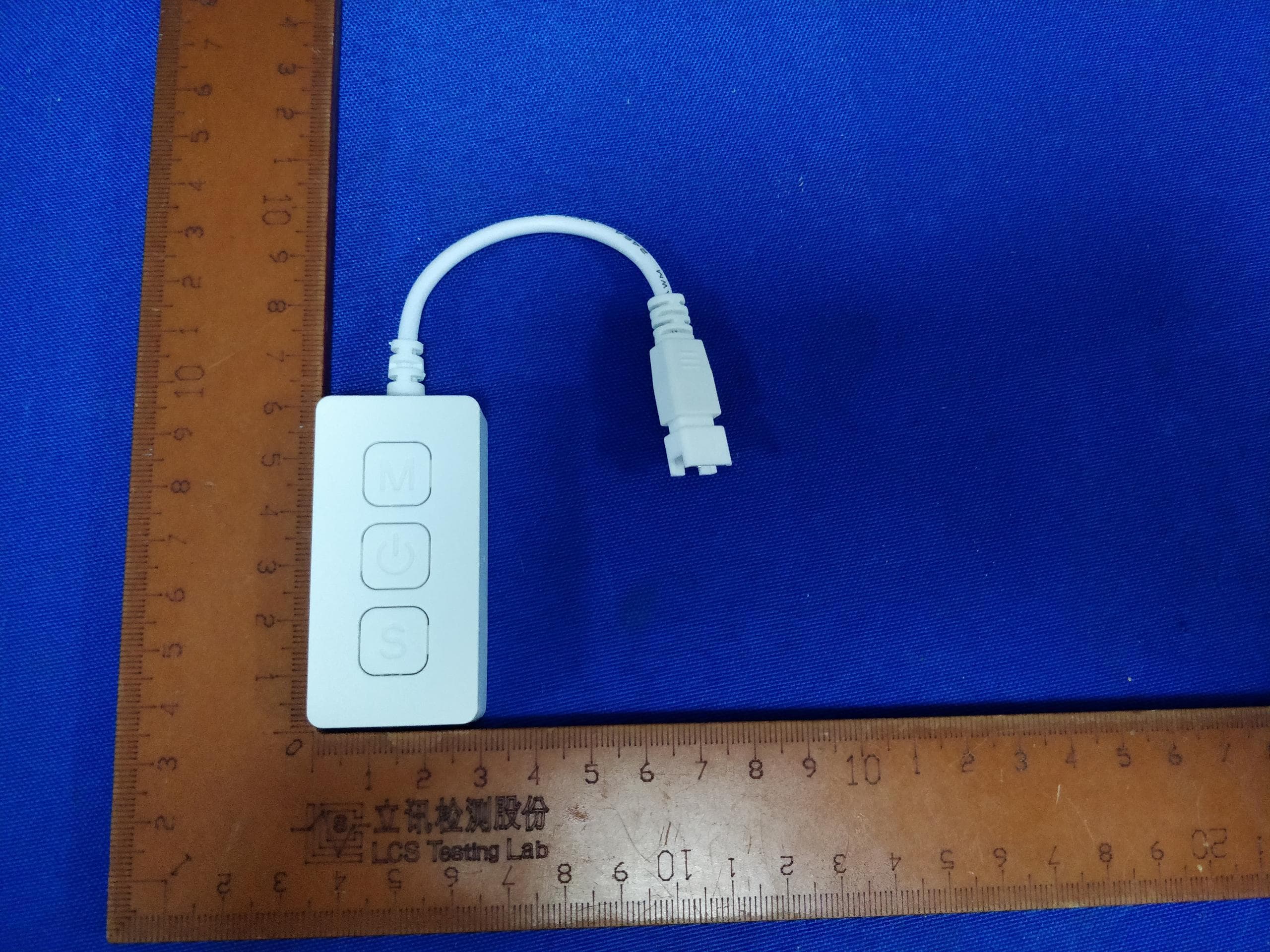
2ATV8SP54XE
Mar 27, 2024LED Controller
Equipment Class
DTS - Digital Transmission System
2ATV8RDX
Mar 26, 20242.4G RF Remote Control
Equipment Class
DTS - Digital Transmission System