2AU6N-VO8364AA915-928MHz terminal
VOGO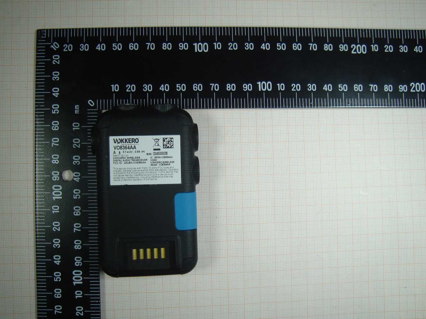
Click to zoom
Application Details
- Equipment Class
- DTS - Digital Transmission System
- Date of Grant
- Jan 21, 2021
- Application Purpose
- Original Equipment
- Date of Application
- Jan 21, 2021
- Equipment Note
- 915-928MHz terminal
- Frequency Range
- 915.40000000 - 927.40000000
- Company
- VOGO
- Country
- France
Documents & Files
Document Text
Text extracted from the exhibit documents filed with the FCC. Open a document above to read the original.
Users Manual
VOKKERO VOGO 101, place Pierre Duhem, Immeuble Les Centuries II, 34000 Montpellier, France www.vokkero.com VOGO NA (North America) 25 Main Street, 3rd Floor Tuckahoe, NY 10707 www.vokkerousa.com 211426 VOKKERO ELITE FCC User Guide Version 1.1 VOKKERO ELITE FCC | User Guide V1.1 2/ 28 • This guide describes the functionality of the system Vokkero® ELITE, options and accessories. It explains how to configure it to allow a conference-type communication between multiple users. • No part of this document may be reproduced or transmitted (in electronic or paper, or photocopying) without the agreement of Vokkero. This document may be changed without notice. All trademarks mentioned in this guide are the subject of intellectual property rights Vok- kero. Web www.VOKKERO.com VOGO 101, place Pierre Duhem, Immeuble Les Centuries II, 34000 Montpellier, France www.vokkero.com VOKKERO ELITE FCC | User Guide V1.1 3/ 28 Table des matières ENGLISH 4 INFORMATIONS 5 DISCLAIMER 5 TECHNICAL SUPPORT 5 INTRODUCTION 9 ENVIRONMENTAL RECOMMENDATIONS 9 WARNINGS 9 DISPOSAL OF WASTE BY USERS IN PRIVATE HOUSEHOLDS WITHIN THE EUROPEAN UNION 10 THIS SYMBOL ON THE DEVODE OR ITS PACKAGING MEANS THE USE OF A DC VOLTAGE. 10 RECOMMANDATIONS REGARDING USE FOR VO8363AAAA & VO7674AAAA 10 1. SYSTEM INSTALLATION PROCEDURE 11 2. SYSTEM DESCRIPTION 12 2.1. VOKKERO ELITE Terminal 12 2.1.1. Description of product interface 12 2.1.2. General characteristics 12 2.2. VOKKERO ELITE Charger/Configurator 13 2.2.1. Description of product interface 13 2.2.2. General Technical Specifications 13 3. QUICK START OF THE CONFERENCE 14 3.1. Setting up Audio Conference 14 3.2. Description of the terminal 14 3.3. Connecting a headset 15 3.3.1. Plugging in a headset 15 3.3.2. Removing the headset 15 3.4. Adjust Volume 15 3.5. Launch a recording 16 3.6. Locking and unlocking the terminal 16 4. START AND HOME SCREEN OF THE CONFIGURATOR 16 4.1. Home Screen 16 5. QUICK CONFIG. MENU 16 5.1. VAR Football «Quick Config.» 16 5.2. Normal “Quick Config.” 18 5.3. CENTRAL REF TO OTHERS AUDIO MODE 19 6. SETTINGS MENU 20 6.1. DEVICES 20 6.1.1. Terminal name 20 6.1.2. Device ID 20 6.1.3. Microphone 21 6.1.4. Audio Matrix 21 6.1.5. Whistle Presets 21 6.1.6. Sidetone 22 6.1.7. Advanced audio 22 6.1.8. Vocal Synthesis 22 6.1.9. SD Card space 23 6.1.10. Factory settings 23 6.1.11. Versions 23 6.2. SYSTEM 24 6.2.1. Channel mode 24 6.2.2. Encryption 24 6.2.3. Software 25 6.3. CONFIGURATOR 26 6.3.1. Backlight 26 6.3.2. Screen calibration 26 6.3.3. Locking 26 6.3.4. Versions / Software 26 DOCUMENT HISTORY 27 VOKKERO ELITE FCC | User Guide V1.1 4/ 28 EN ENGLISH 5/ 28 VOKKERO ELITE FCC | User Guide V1.1 EN INFORMATIONS Document Information Title VOKKERO ELITE FCC Subtitle ELITE Document type User Guide Version Version 1.1 This document applies to the following products: NameReference VOKKERO ELITE FCC - ELITE From : VO8364AA VOKKERO ELITE - Configurator From : VO7674AA VOKKERO ELITE - Charger From : VO8363AA DISCLAIMER This document and the use of any information contained therein, is subject to the acceptance of the VOK- KERO terms and conditions. They can be downloaded from www.vokkero.com VOKKERO makes no warranties based on the accuracy or completeness of the contents of this document and reserves the right to make changes to specifications and product descriptions at any time without notice. VOKKERO reserves all rights to this document and the information contained herein. Reproduction, use or disclosure to third parties without express permission is strictly prohibited. Copyright © 2016, VOKKERO. VOKKERO is a registered trademark in the EU and other countries. TECHNICAL SUPPORT Website Our website contains a lot of useful information: information on modules and wireless modems, user guides, and configuration software and technical documents which can be accessed 24 hours a day. If you have technical problems or cannot find the required information in the provided documents, contact our Technical Support on our website: www.vokkero.com. This ensures that your request will be processed as soon as possible. Helpful Information when Contacting Technical Support When contacting Technical Support, please have the following information ready: • Product type • Firmware version (for example V1.0) • A clear description of your question or the problem • A short description of the application 6/ 28 COMPLIANCE TO FCC US/CAN This device complies with part 15 of the FCC rules and Industry Canada licence-exempt RSS standard(s). Operation is subject to the following two conditions: (1). this device may not cause Harmful interference, and (2). this device must accept any interference received, including interference that may cause undesired operation of the device. This equipment has been tested and found to comply with the limits for a Class B digital device, pursuant to part 15 of the FCC Rules. These limits are designed to provide reasonable protection against harmful interference in a residential installation. This equipment generates, uses and can radiate radio frequency energy and, if not installed and used in accordance with the instruction, may cause harmful interference to radiocommunication. However, there is no guarantee that interference will not occur in a particular installation. If this equipment does cause harmful interference to radio or television reception, which can be determined by turning the equipment off and on, the user is encouraged to try to correct the interference by one or more of the following measures : - Reorient or relocate the receiving antenna. - Increase the separation between the equipment and receiver. - Connect the equipment into an outlet on a circuit different from that to which the receiver is connected. - Consult the dealer or an experienced radio/TV technician for help. Changes or modifications not expressly approved by VOGO could void the user’sauthority to operate the equipment. This device is limited to operating the frequencies authorized…
Text truncated - open the document above for the full version.
Cover Letter(s)
Document Version 1.1 2020-10-30 LONG-TERM CONFIDENTIALITY REQUEST for Certification Service in the USA Federal Communication Commission Equipment Authorization Division, Application Processing Branch 7435 Oakland Mills Road Columbia, MD 21048 TO WHOM IT M AY CONCERN Pursuant to Paragraphs §0.457 and 0.459 of the Commission’s Rules (47 C.F.R.) and Section §552(b)(4) of the Freedom of Information Act, we request Long-Term Confidentiality for the following product: For the product stated above, we request Long-Term Confidentiality for exhibits which contain Block Diagram, Operational Description, Parts List/Tune Up Info, Schematics, SDR Software/Security Info. The above exhibits contain ou r trade secrets and proprietary information that could be of benefit to o ur competitors. This information will not be publicly available. If you have any questions, please feel free to contact us at the address shown below. Sincerely, Company Name: Phone: Company Address: Fax: E-mail: Contact Name: Signature: Signature Date: Check your GC here. Click Grantee Search. FCC I D: Grantee Code Equipment Product Code
External Photos
Annex A 1-1524/20-01-01_AnnexA External photos of the Equipment Under Test This addendum is electronically signed and valid without handwritten signature. For verification of the electronic signatures, the public keys can be requested at the testing laboratory. Document authorized: Hans-Joachim Wolsdorfer Lab Manager Radio Communications & EMC CTC advanced GmbHUntertuerkheimer Str. 6-10 66117 Saarbruecken / Germany Phone: +49 681 5 98 - 0 Fax: +49 681 5 98 - 9075 web: ctcadvanced.com e-mail: [email protected] Photos Photo 1 Photo 2 2021-01-12Document No. 1-1524/20-01-01_AnnexA2/5 Photo 3 Photo 4 2021-01-12Document No. 1-1524/20-01-01_AnnexA3/5 Photo 5 2021-01-12Document No. 1-1524/20-01-01_AnnexA4/5 Document history VersionApplied changesDate of release initial release2021-01-12 - END OF DOCUMENT - 2021-01-12Document No. 1-1524/20-01-01_AnnexA5/5
ID Label/Location Info
VOKKERO ELITE 915 TERMINAL VO8364AA LABEL AND LABEL LOCATION INFO V1.0 1.Label of the VO8364AA : 1.Label location of the VO8364AA :
Internal Photos
Annex B 1-1524/20-01-01_AnnexB Internal photos of the Equipment Under Test This addendum is electronically signed and valid without handwritten signature. For verification of the electronic signatures, the public keys can be requested at the testing laboratory. Document authorized: Hans-Joachim Wolsdorfer Lab Manager Radio Communications & EMC CTC advanced GmbHUntertuerkheimer Str. 6-10 66117 Saarbruecken / Germany Phone: +49 681 5 98 - 0 Fax: +49 681 5 98 - 9075 web: ctcadvanced.com e-mail: [email protected] Photos Photo 1 Photo 2 2021-01-15Document No. 1-1524/20-01-01_AnnexB2/3 Document history VersionApplied changesDate of release initial release2021-01-15 - END OF DOCUMENT - 2021-01-15Document No. 1-1524/20-01-01_AnnexB3/3
RF Exposure Info
© CTC advanced GmbH Page 1 of 38 BNetzA - CAB - 02/21 - 102 D - P L - 1 2 0 7 6 - 0 1 - 0 3 TEST REPORT Test Report No.: 1-1524/20-01-04-A Testing Laboratory Applicant CTC advanced GmbH Untertuerkheimer Strasse 6 – 10 66117 Saarbruecken/Germany Phone: + 49 681 5 98 - 0 Fax: + 49 681 5 98 - 9075 Internet: https://www.ctcadvanced.com e-mail: [email protected] Accredited Test Laboratory: The testing laboratory (area of testing) is accredited according to DIN EN ISO/IEC 17025 (2005) by the Deutsche Akkreditierungsstelle GmbH (DAkkS) The accreditation is valid for the scope of testing procedures as stated in the accreditation certificate with the registration number: D-PL-12076-01-03 VOGO 101 place Pierre Duhem – Immeuble Les Centuries II 3400 Montpellier/FRANCE Phone: +33 6 43 78 76 85 Contact: Pascal Saguin e-mail: [email protected] Phone: +33 6 43 78 76 85 Manufacturer VOGO Parc Technologique des Fontaines – Activillage 3A 38190 Bernin/FRANCE Test Standards IEEE 1528-2013 Recommended Practice for Determining the Peak Spatial-Average Specific Absorption Rate (SAR) in the Human Head from Wireless Communications Devices: Measurement Techniques RSS-102 Issue 5 Radio Frequency Exposure Compliance of Radiocommunication Apparatus (All Frequency Bands) For further applied test standards please refer to section 3 of this test report. Test Item Kind of test item: Wireless Digital Audio Transceiver Device type: portable device Model name: VO8364AA S/N serial number: I2045000038 FCC-ID: 2AU6N-VO8364AA ISED Number: 25704- VO8364AA Product Marketing Name (PMN): Vokkero ELITE 915 Terminal Hardware Version Identification No. (HVIN): VO8364AA FVIN: V01-07.00-07.00 Frequency: DTS or Hopping 900 MHz Antenna: integrated antenna Battery option: 3.7 Vdc by lithium battery Test sample status: identical prototype Exposure category: general population / uncontrolled environment This test report is electronically signed and valid without handwriting signature. For verification of the electronic signatures, the public keys can be requested at the testing laboratory. Test Report authorised: Test performed: Alexander Hnatovskiy Marco Scigliano Lab Manager Testing Manager Radio Communications Radio Communications Test report no.: 1-1524/20-01-04-A © CTC advanced GmbH Page 2 of 38 1 Table of contents 1 Table of contents ....................................................................................................................................... 2 2 General information .................................................................................................................................. 3 2.1 Notes and disclaimer ..................................................................................................................... 3 2.2 Application details ......................................................................................................................... 3 2.3 Statement of compliance ............................................................................................................... 3 3 Test standards/ procedures references .................................................................................................. 4 3.1 RF exposure limits ......................................................................................................................... 5 4 Summary of Measurement Results ......................................................................................................... 6 5 Test Environment ...................................................................................................................................... 6 6 Test Set-up ................................................................................................................................................. 7 6.1 Measurement system ..................................................................................................................... 7 6.1.1 System Description ................................................................................................................ 7 6.1.2 Test environment ................................................................................................................... 8 6.1.3 Probe description ................................................................................................................... 8 6.1.4 Phantom description .............................................................................................................. 9 6.1.5 Device holder description .................................................................................................... 10 6.1.6 Scanning procedure ............................................................................................................ 11 6.1.7 Comparison of DASY 52 NEO and cDASY6 ....................................................................... 15 6.1.8 Spatial Peak SAR Evaluation .............................................................................................. 16 6.1.9 Data Storage and Evaluation............................................................................................... 19 6.1.10 Tissue simulating liquids: dielectric properties .................................................................... 21 6.1.11 Tissue simulating liquids: parameters ................................................................................. 21 6.1.12 Measurement uncertainty evaluation for SAR test .............................................................. 22 6.1.13 Measurement uncertainty evaluation for System Check ..................................................... 25 6.1.14 System check ...................................................................................................................... 26 6.1.15 System check procedure ..................................................................................................... 27 6.1.16 System validation .....................................…
Text truncated - open the document above for the full version.
RF Exposure Info
Page 1 of 33 Annex D Appendix to Test Report No.: 1-1524/20-01-04-A Testing Laboratory CTC advanced GmbH Untertürkheimer Straße 6 – 10 66117 Saarbrücken/Germany Phone: + 49 681 5 98 - 0 Fax: + 49 681 5 98 - 9075 Internet: http://www.ctcadvanced.com e-mail: [email protected] Accredited Test Laboratory: The testing laboratory (area of testing) is accredited according to DIN EN ISO/IEC 17025 (2005) by the Deutsche Akkreditierungsstelle GmbH (DAkkS) The accreditation is valid for the scope of testing procedures as stated in the accreditation certificate with the registration number: D-PL-12076-01-01 Appendix with Calibration data, Phantom certificate and system check information 2012-01-16 Test report no.: 1-1524/20-01-04-A Page 2 of 33 1 Table of contents 1 Table of contents ....................................................................................................................................... 2 2 Calibration report “Probe EX3DV4” ........................................................................................................ 3 3 Calibration report “900 MHz System validation dipole” ...................................................................... 13 4 Calibration certificate of Data Acquisition Unit (DAE) ........................................................................ 25 5 Certificate of “SAM Twin Phantom V4.0/V4.0C’’ ................................................................................. 26 6 Application Note System Performance Check ..................................................................................... 27 6.1 Purpose of system performance check ..................................................................................... 27 6.2 System Performance check procedure ...................................................................................... 27 6.3 Uncertainty Budget ...................................................................................................................... 28 6.4 Power set-up for validation ......................................................................................................... 32 6.5 Laboratory reflection ................................................................................................................... 33 6.6 Additional system checks ........................................................................................................... 33 Test report no.: 1-1524/20-01-04-A Page 3 of 33 2 Calibration report “Probe EX3DV4” Test report no.: 1-1524/20-01-04-A Page 4 of 33 Test report no.: 1-1524/20-01-04-A Page 5 of 33 Test report no.: 1-1524/20-01-04-A Page 6 of 33 Test report no.: 1-1524/20-01-04-A Page 7 of 33 Test report no.: 1-1524/20-01-04-A Page 8 of 33 Test report no.: 1-1524/20-01-04-A Page 9 of 33 Test report no.: 1-1524/20-01-04-A Page 10 of 33 Test report no.: 1-1524/20-01-04-A Page 11 of 33 Test report no.: 1-1524/20-01-04-A Page 12 of 33 Test report no.: 1-1524/20-01-04-A Page 13 of 33 3 Calibration report “900 MHz System validation dipole” Test report no.: 1-1524/20-01-04-A Page 14 of 33 Test report no.: 1-1524/20-01-04-A Page 15 of 33 Test report no.: 1-1524/20-01-04-A Page 16 of 33 Test report no.: 1-1524/20-01-04-A Page 17 of 33 Test report no.: 1-1524/20-01-04-A Page 18 of 33 Test report no.: 1-1524/20-01-04-A Page 19 of 33 Test report no.: 1-1524/20-01-04-A Page 20 of 33 Test report no.: 1-1524/20-01-04-A Page 21 of 33 Antenna Parameters with Head TSL From cal. data Measured 2019-09-11 Impedance; transformed to feed point 49.5 Ω - 2.0 jΩ 49.0 Ω - 1.7 jΩ Return Loss -33.7 dB -33.9 dB Test report no.: 1-1524/20-01-04-A Page 22 of 33 Antenna Parameters with Body TSL From cal. data Measured 2019-09-11 Impedance; transformed to feed point 45.2 Ω - 4.6 jΩ 46.2 Ω - 4.5 jΩ Return Loss -23.1 dB -24.2 dB Test report no.: 1-1524/20-01-04-A Page 23 of 33 Antenna Parameters with Head TSL From cal. data Measured 2020-09-21 Impedance; transformed to feed point 49.5 Ω - 2.0 jΩ 48.7 Ω - 1.0 jΩ Return Loss -33.7 dB -36.5 dB Test report no.: 1-1524/20-01-04-A Page 24 of 33 Antenna Parameters with Body TSL From cal. data Measured 2020-09-21 Impedance; transformed to feed point 45.2 Ω - 4.6 jΩ 45.2 Ω - 4.3 jΩ Return Loss -23.1 dB -23.4 dB Test report no.: 1-1524/20-01-04-A Page 25 of 33 4 Calibration certificate of Data Acquisition Unit (DAE) Test report no.: 1-1524/20-01-04-A Page 26 of 33 5 Certificate of “SAM Twin Phantom V4.0/V4.0C’’ Test report no.: 1-1524/20-01-04-A Page 27 of 33 6 Application Note System Performance Check 6.1 Purpose of system performance check The system performance check verifies that the system operates within its specifications. System and operator errors can be detected and corrected. It is recommended that the system performance check is performed prior to any usage of the system in order to guarantee reproducible results. The measurement of the Specific Absorption Rate (SAR) is a complicated task and the result depends on the proper functioning of many components and the correct settings of many parameters. Faulty results due to drift, failures or incorrect parameters might not be recognized, since they often look similar in distribution to the correct ones. The Dosimetric Assessment System DASY5 incorporates a system performance check procedure to test the proper functioning of the system. The system performance check uses normal SAR measurements in a simplified setup (the flat section of the SAM Twin Phantom) with a well characterized source (a matched dipole at a specified distance). This setup was selected to give a high sensitivity to all parameters that might fail or vary over time (e.g., probe, liquid parameters, and software settings) and a low sensitivity to external effects inherent in the system (e.g., positioning uncertainty of the device holder). The system performance check does not replace the calibration of the components. The accuracy of the system performance check is not sufficient for calibration pu…
Text truncated - open the document above for the full version.
RF Exposure Info
Page 1 of 7 BNetzA - CAB - 02/21 - 102 Annex C Photo documentation Appendix to Test Report No.: 1-1524/20-01-04-A Testing Laboratory CTC advanced GmbH Untertürkheimer Straße 6 – 10 66117 Saarbrücken/Germany Phone: + 49 681 5 98 - 0 Fax: + 49 681 5 98 - 9075 Internet: http://www.ctcadvanced.com e-mail: [email protected] Accredited Test Laboratory: The testing laboratory (area of testing) is accredited according to DIN EN ISO/IEC 17025 (2005) by the Deutsche Akkreditierungsstelle GmbH (DAkkS) The accreditation is valid for the scope of testing procedures as stated in the accreditation certificate with the registration number: D-PL-12076-01-03 D-PL-12076-01-03 Test report no.: 1-1524/20-01-04-A Page 2 of 7 Photo 1: Measurement System DASY 5 Photo 2: DUT - Front view Test report no.: 1-1524/20-01-04-A Page 3 of 7 Photo 3: DUT - Rear view Photo 4: DUT - Rear view (Label) Test report no.: 1-1524/20-01-04-A Page 4 of 7 Photo 5: DUT - Side view (Label) Photo 6: DUT - Top side view (Label) Test report no.: 1-1524/20-01-04-A Page 5 of 7 Photo 7: Test position - Front with 0mm distance Photo 8: Test position - Rear with 0mm distance Test report no.: 1-1524/20-01-04-A Page 6 of 7 Photo 9: Test position - Left side with 0mm distance Photo 10: Test position - Right side with 0mm distance Test report no.: 1-1524/20-01-04-A Page 7 of 7 Photo 11: Test position - Top side with 0mm distance Photo 12: Test position - Bottom side with 0mm distance
Test Report
TEST REPORT Test report no.: 1-1524/20-01-02-A Testing laboratory Applicant CTC advanced GmbH Untertuerkheimer Strasse 6 – 10 66117 Saarbruecken / Germany Phone: + 49 681 5 98 - 0 Fax: + 49 681 5 98 - 9075 Internet: https://www.ctcadvanced.com e-mail: [email protected] Accredited Testing Laboratory: The testing laboratory (area of testing) is accredited according to DIN EN ISO/IEC 17025 (2018-03) by the Deutsche Akkreditierungsstelle GmbH (DAkkS) The accreditation is valid for the scope of testing procedures as stated in the accreditation certificate starting with the registration number: D-PL-12076-01. VOGO 101 place Pierre Duhem – Immeuble Les Centuries II 3400 Montpellier / FRANCE Phone: +33 6 43 78 76 85 Contact: Pascal Saguin e-mail: [email protected] Manufacturer VOGO Parc Technologique des Fontaines – Activillage 3A 38190 Bernin / FRANCE Test standard/s FCC - Title 47 CFR Part 15 FCC - Title 47 of the Code of Federal Regulations; Chapter I; Part 15 - Radio frequency devices RSS - 247 Issue 2 Digital Transmission Systems (DTSs), Frequency Hopping Systems (FHSs) and Licence - Exempt Local Area Network (LE-LAN) Devices For further applied test standards please refer to section 3 of this test report. Test Item Kind of test item: DIGITAL AUDIO TRANSCEIVER Model name: VO8364AA (VOKKERO ELITE 915 Terminal) FCC ID: 2AU6N-VO8364AA IC: 25704-VO8364AA Frequency: DTS band 902 – 928 MHz Technology tested: Proprietary DTS/FHSS Antenna: Integrated antenna Power supply: 3.7 V DC by lithium battery Temperature range: -20°C to +55°C This test report is electronically signed and valid without handwritten signature. For verification of the electronic signatures, the public keys can be requested at the testing laboratory. Test report authorized: Test performed: p.o. Christoph Schneider Tobias Wittenmeier Lab Manager Testing Manager Radio Communications Radio Communications Test report no.: 1-1524/20-01-02-A © CTC advanced GmbH Page 2 of 84 1 Table of contents 1 Table of contents ............................................................................................................................................. 2 2 General information ......................................................................................................................................... 4 2.1 Notes and disclaimer ............................................................................................................................ 4 2.2 Application details ................................................................................................................................ 4 2.3 Test laboratories sub-contracted ......................................................................................................... 4 3 Test standard/s, references and accreditations .............................................................................................. 5 4 Reporting statements of conformity – decision rule ...................................................................................... 6 5 Test environment ............................................................................................................................................. 7 6 Test item .......................................................................................................................................................... 7 6.1 General description ............................................................................................................................... 7 6.2 Additional information .......................................................................................................................... 7 7 Description of the test setup............................................................................................................................ 8 7.1 Shielded semi anechoic chamber ......................................................................................................... 9 7.2 Shielded fully anechoic chamber ........................................................................................................ 11 7.3 Conducted measurements .................................................................................................................. 12 8 Sequence of testing ....................................................................................................................................... 13 8.1 Sequence of testing radiated spurious 9 kHz to 30 MHz ................................................................... 13 8.2 Sequence of testing radiated spurious 30 MHz to 1 GHz .................................................................. 14 8.3 Sequence of testing radiated spurious 1 GHz to 18 GHz ................................................................... 15 9 Measurement uncertainty .............................................................................................................................. 16 10 Summary of measurement results ............................................................................................................. 17 10.1 Part 1: FHSS .................................................................................................................................... 17 10.2 Part 2: DTS ....................................................................................................................................... 18 11 RF measurements ...................................................................................................................................... 19 11.1 Additional comments ...................................................................................................................... 19 12 Measurement results Part 1 FHSS ............................................................................................................. 21 12.1 Antenna gain ..............................................................................................…
Text truncated - open the document above for the full version.
Test Setup Photos
Annex D 1-1524/20-01-01_AnnexD Setup photos of the Equipment Under Test This addendum is electronically signed and valid without handwritten signature. For verification of the electronic signatures, the public keys can be requested at the testing laboratory. Document authorized: Hans-Joachim Wolsdorfer Lab Manager Radio Communications & EMC CTC advanced GmbHUntertuerkheimer Str. 6-10 66117 Saarbruecken / Germany Phone: +49 681 5 98 - 0 Fax: +49 681 5 98 - 9075 web: ctcadvanced.com e-mail: [email protected] Photos Photo 1 Photo 2 2021-01-12Document No. 1-1524/20-01-01_AnnexD2/4 Photo 3 2021-01-12Document No. 1-1524/20-01-01_AnnexD3/4 Document history VersionApplied changesDate of release initial release2021-01-12 - END OF DOCUMENT - 2021-01-12Document No. 1-1524/20-01-01_AnnexD4/4
Contact Information
Applicant
Pascal SAGUIN
Test Firm
cetecom advanced GmbHGerald Schmidt
Technical Specifications
| # | Rule Parts | Frequency Range | Power Output |
|---|---|---|---|
| 1 | 15C | 915.4 MHz - 927.4 MHz | 112.20 mW |
Other Applications from VOGO
2AU6N-VO8438CABT
Jul 09, 2023VOK-GUARD/SHOW-US/CAN/AUS/NZ
Equipment Class
DTS - Digital Transmission System
2AU6N-VO8161C
Jan 21, 2021915-928MHz wireless Interface
Equipment Class
DSS - Part 15 Spread Spectrum Transmitter
2AU6N-VO8230GUARD
Dec 20, 2020WI VOKKERO GUARDIAN US CAN
Equipment Class
DTS - Digital Transmission System
2AU6N-VO8161
Mar 30, 2020WI VOKKERO GUARDIAN US CAN
Equipment Class
DSS - Part 15 Spread Spectrum Transmitter