2AU6S-HGBTBluetooth earphone with Bluetooth Transmitter
LUCID AUDIO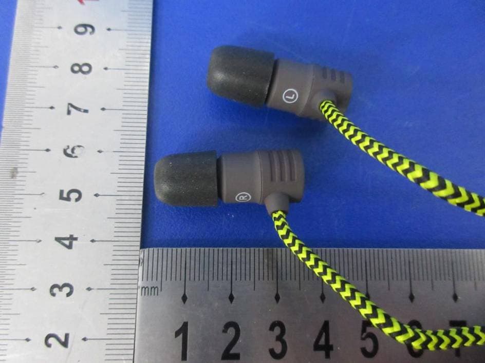
Click to zoom
Application Details
- Equipment Class
- DSS - Part 15 Spread Spectrum Transmitter
- Date of Grant
- Feb 26, 2020
- Application Purpose
- Original Equipment
- Date of Application
- Feb 26, 2020
- Equipment Note
- Bluetooth earphone with Bluetooth Transmitter
- Frequency Range
- 2402.00000000 - 2480.00000000
- Company
- LUCID AUDIO
- Country
- United States
Documents & Files
Document Text
Text extracted from the exhibit documents filed with the FCC. Open a document above to read the original.
Users Manual
A. POWERING ON/OFF 1.Press and hold BLUETOOTH BUTTON for 3 seconds and INDICATOR LIGHT will flash BLUE 3 times. 2. The earphone will then enter automatic pairing and the INDICATOR LIGHT will flash RED and BLUE alternately. 3. Enter your Bluetooth settings on your device and connect earphones by choosing "TV HearGear BT" or connect to your TV HearGear Streamer 4. Once connected, the INDICATOR LIGHT will flash BLUE slowly and your earphone will be ready to use. 5. Once you complete use of your earphone, press and hold the BLUETOOTH BUTTON for 3 seconds and the INDICATOR LIGHT will flash RED 3 times. Your earphones are now turned off. B. WHILE IN USE FOR CALLS - Tap the BLUETOOTH BUTTON once to pick up or end calls. - Tap the BLUETOOTH BUTTON twice to redial the last incoming or outgoing number. - When there is another incoming call during a call, tap the BLUETOOTH BUTTON once to end original call and receive a new call. Tap the BLUETOOTH BUTTON twice to put the original call on hold and receive a new call. Tap BLUETOOTH BUTTON twice to alternate between the two calls . FOR MEDIA - Tap BLUETOOTH BUTTON once to play/pause music - Tap VOLUME UP/DOWN BUTTON once to increase/decrease media volume. - Press and hold VOLUME UP/DOWN BUTTON for 2 seconds to skip to previous/next track. - Press and hold BLUETOOTH BUTTON to activate SI RI /BIXBY/ALEXA etc ... platforms. C. SILICONE TIP FITTING PROCEDURE 1. Select the proper size ear tip to fit your ear canal according to your best comfort. D. BATTERY CHARGING 1.lnsert USB charging cable to an AC charger ( not included) or a computer USB port. 2.lnsert the Micro USB end into charge port. 3.The Led indicator lights up RED while the unit is being charged. Once battery is fully charged, the light will turn BLUE . 4.Battery charging time is approximately 2 hours. FCC STATEMENT 1. This device complies with Part 15 of the FCC Rules. Operation is subject to the following two conditions: (1) This device may not cause harmful interference. (2) This device must accept any interference received, including interference that may cause undesired operation. 2. Changes or modifications not expressly approved by the party responsible for compliance could void the user's authority to operate the equipment. NOTE: This equipment has been tested and found to comply with the limits for a Class B digital device, pursuant to Part 15 of the FCC Rules. These limits are designed to provide reasonable protection against harmful interference in a residential installation. This equipment generates uses and can radiate radio frequency energy and, if not installed and used in accordance with the instructions, may cause harmful interference to radio communications. However, there is no guarantee that interference will not occur in a particular installation. If this equipment does cause harmful interference to radio or television reception, which can be determined by turning the equipment off and on, the user is encouraged to try to correct the interference by one or more of the following measures: Reorient or relocate the receiving antenna. Increase the separation between the equipment and receiver. Connect the equipment into an outlet on a circuit different from that to which the receiver is connected. Consult the dealer or an experienced radio/TV technician for help. RF warning statement: The device has been evaluated to meet general RF exposure requirement. The device can be used in portable exposure condition without restriction. IC WARNING This device contains licence-exempt transmitter(s)/receiver(s) that comply with Innovation, Science and Economic Development Canada’s licence-exempt RSS(s). Operation is subject to the following two conditions: (1) This device may not cause interference. (2) This device must accept any interference, including interference that may cause undesired operation of the device. Cet appareil contient des émetteurs / récepteurs exemptés de licence conformes aux RSS (RSS) d'Innovation, Sciences et Développement économique Canada. Le fonctionnement est soumis aux deux conditions suivantes : (1) Cet appareil ne doit pas causer d'interférences. (2) Cet appareil doit accepter toutes les interférences, y compris celles susceptibles de provoquer un fonctionnement indésirable de l'appareil. MODEL: ERHG-BT FCC ID: 2AU6S-HGBT IC: 25701-HGBT MADE IN CHINA
Cover Letter(s)
Jan 15, 2020 Federal C ommunications Commission Authorization & Evaluation Division 7345 Oakland Mills Road Columbia, Maryland 21046 Authority to Act as Agent On our behalf, I appoint EMTEK(SHENZHEN) CO., LTD. (Bldg 69, Majialong Industry Zone, Nanshan District, Shenzhen, Guangdong, China) to act as our agent in the preparation of this application for equipment certification. I certify that submitted documents properly describe the device or system for which equipment certification is sought. I also c ertify that each unit manufactured, imported or marketed, as defined in the Federal Communications Commission’s regulations will have affixed to it a label identical to that submitted for approval with this application. For instances where our authorized agent signs the application for certification on our behalf, I acknowledge that all responsibility for complying with the terms and conditions for certification, still resides with LUCID AUDIO Name: Tal Kocen Title: MR Company: LUCID AUDIO
Cover Letter(s)
Jan 15, 2020 Equipment Autorisation Division Federal Communications Commission 7435 Oakland Mills Road Columbia, MD 21046 FCC ID: 2AU6S-HGBT Product Name: Bluetooth earphone with Bluetooth Transmitter Request for Confidentiality Pursuant to Sections 0.457 and 0.459 of the commissions rules, we hereby request that the following documents be held confidential: (List here the documents for which you are seeking confidentiality – for example ...) Schematics Block diagram Operation description These materials contain trade secrets and proprietary information and are not customarily released to the public. The public disclosure of this information might be harmful to the company and provide unjustified benefits to our competitors. Name: Tal Kocen Title: MR Company: LUCID AUDIO
External Photos
External photos: ---The End---
Internal Photos
Internal photos: ---The End---
RF Exposure Info
FCC ID: 2AU6S-HGBT IC: 25701-HGBT RF EXPOSURE EVALUATION Test standard: CFR47 FCC Part 2.1091 RSS-102 Issue 5 March 2015 FCC KDB Publication 447498 v06 According to 447498 D01 General RF Exposure Guidance v05 The 1-g and 10-g SAR test exclusion thresholds for 100 MHz to 6 GHz at test separation distances≤ 50 mm are determined by: [(max. power of channel, including tune-up tolerance, mW)/(min. test separation distance, mm)] ·[√f(GHz)] ≤ 3.0 for 1-g SAR and ≤ 7.5 for 10-g extremity SAR, where f(GHz) is the RF channel transmit frequency in GHz Power and distance are rounded to the nearest mW and mm before calculation The measured maximum conducted power of the EUT is 3.614dBm ≈ 2.30 mW, which is far below the SAR exclusion threshold level 96mW (Appendix A, SAR Test Exclusion Thresholds for 100 MHz – 6 GHz and ≤50 mm), hence the EUT is excluded from SAR evaluation according to FCC KDB publication 447498 D01: Mobile and Portable RF Exposure. Guidance v06. According to RSS-102 Issue 5 March 2015 SAR evaluation is required if the separation distance between the user and/or bystander and the antenna and/or radiating element of the device is less than or equal to 20 cm, except when the device operates at or below the applicable output power level (adjusted for tune-up tolerance) for the specified separation distance defined in Table . Limits for SAR evaluation RF exposure evaluation is required if the separation distance between the user and/or bystander and the device’s radiating element is greater than 20 cm, except when the device operates as follows: • at or above 300 MHz and below 6 GHz and the source-based, time-averaged maximum e.i.r.p. of the device is equal to or less than 1.31 x 10⁻² ƒ 0.6834 W (adjusted for tune-up tolerance), where ƒ is in MHz; The separation distance of the EUT should be less than 5mm.The measured maximum specified e.i.r.p of the EUT is 5.614dBm ≈ 3.64mW, which is far below the SAR exclusion threshold level 4mW, hence the EUT is excluded from SAR evaluation according to RSS-102 Issue 5 section 2.5.1. 2.3 X √2.441 / 5 = 0.72 <3
Test Report
Report No. ES191227030W TEST REPORT Product Name Model Number FCC ID IC Prepared for : LUCID AUDIO Address : 14301 Faa Blvd, Ft Worth, Tx 76155, U Prepared by : EMTEK (SHENZHEN) CO., LTD. Address : Bldg 69, Majialong Industry Zone, Nanshan District, Shenzhen, Guangdong, China Tel: (0755) 26954280 Fax: (0755) 26954282 Report Number : ES191227030W Date(s) of Tests : December 2 Date of issue : Febr Page 1 of 60 TEST REPORT : Bluetooth earphone with Bluetooth Transmitter : ERHG-BT : 2AU6S-HGBT : 25701-HGBT LUCID AUDIO 14301 Faa Blvd, Ft Worth, Tx 76155, U SA EMTEK (SHENZHEN) CO., LTD. Bldg 69, Majialong Industry Zone, Nanshan District, Shenzhen, Guangdong, China Tel: (0755) 26954280 Fax: (0755) 26954282 ES191227030W December 2 7, 2019 to January 15, 2020 Febr uary 25, 2020 Ver.1.0 $二维码$ Bluetooth earphone with Bluetooth Bldg 69, Majialong Industry Zone, Nanshan District, Report No. ES191227030W 1 TEST RESULT CERTIFICATION 2 GENERAL INFORMATION ................................ 2.1 EUT TECHNICAL DESCRIPTION 3 SUMMARY OF TEST RESU 4 TEST METHODOLOGY ................................ 4.1 GENERAL DESCRIPTION 4.2 MEASUREMENT EQUIPMENT 4.3 DESCRIPTION OF TEST 5 FACILITIES AND ACCREDITATIONS 5.1 FACILITIES................................ 5.2 LABORATORY ACCREDITATIONS 5.3 TEST SOFTWARE ................................ 6 TEST SYSTEM UNCERTAINTY 7 SETUP OF EQUIPMENT UNDER TEST 7.1 RADIO FREQUENCY TEST 7.2 RADIO FREQUENCY TEST 7.3 CONDUCTED EMISSION 7.4 SUPPORT EQUIPMENT 8 FREQUENCY HOPPING SY 8.1 STANDARD APPLICABLE ................................ 8.2 EUT PSEUDORANDOM FREQUENCY 8.3 EQUAL HOPPING FREQUENCY 8.4 FREQUENCY HOPPING SYSTEM 9 TEST REQUIREMENTS ................................ 9.1 20DB BANDWIDTH ................................ 9.2 CARRIER FREQUENCY 9.3 NUMBER OF HOPPING 9.4 AVERAGE TIME OF OCCUPANCY 9.5 MAXIMUM PEAK CONDUCTED 9.6 CONDUCTED SUPRIOUS 9.7 RADIATED SPURIOUS 9.8 CONDUCTED EMISSION 9.9 ANTENNA APPLICATION Page 2 of 60 Table of Contents ATION ................................................................................................ ................................................................................................ DESCRIPTION ................................................................................................ SUMMARY OF TEST RESULT ................................................................................................ ................................................................................................ DESCRIPTION OF APPLIED STANDARDS ................................ EQUIPMENT USED ................................................................ TEST MODES ................................................................................................ DITATIONS ................................................................................................ ................................................................................................................................ ACCREDITATIONS AND LISTINGS ................................................................ ................................................................................................................................ NTY ................................................................................................ NDER TEST ................................................................................................ TEST SETUP 1 ................................................................ TEST SETUP 2 ................................................................ EMISSION TEST SETUP ................................................................ EQUIPMENT................................................................................................ FREQUENCY HOPPING SYSTEM REQUIREMENTS ................................................................ ................................................................................................ REQUENCY HOPPING SEQUENCE ................................................................ REQUENCY USE ................................................................................................ YSTEM ................................................................................................ ................................................................................................ ................................................................................................ FREQUENCY SEPARATION ................................................................ HOPPING FREQUENCIES ................................................................ OCCUPANCY (DWELL TIME) ................................................................ CONDUCTED OUTPUT POWER ................................................................ SUPRIOUS EMISSION ................................................................ SPURIOUS EMISSION ................................................................................................ EMISSION TEST ................................................................................................ APPLICATION ................................................................................................ Ver.1.0 .......................................................... 3 ................................................................... 4 ............................................. 4 .............................................................. 5 ........................................................................ 6 .......................................................................... 6 ..................................................................... 6 .............................................. 7 ................................................. 8 .................................................. 8 .............................................. 8 ............................................ 8 ..........................................…
Text truncated - open the document above for the full version.
Test Report
Report No. ES191227030W Test Model Test Model Page 36 of 60 Maximum PeakConducted Output Power Channel 0: 2402MHz Maximum PeakConducted Output Power Channel 39: 2441MHz Ver.1.0 Maximum PeakConducted Output Power 8DPSK Maximum PeakConducted Output Power 8DPSK Report No. ES191227030W Test Model Page 37 of 60 Maximum PeakConducted Output Power Channel 78: 2480MHz Ver.1.0 Maximum PeakConducted Output Power 8DPSK Report No. ES191227030W 9.6 CONDUCTED SUPRIOUS 9.6.1 Applicable Standard According to FCC Part 15.247(d) 9.6.2 Conformance Limit According to FCC Part 15.247(d) In any 100 kHz bandwidth outside the frequency band in which the spread spectrum intentional radiator is operating, the radio frequency pow below that in the 100 kHz bandwidth within the band that contains the highest level of the desired power, based on either an RF conducted, provided the transmitter demonstrates complia conducted power limits. 9.6.3 Test Configuration Test according to clause 7.1 radio frequency test setup 1 9.6.4 Test Procedure The transmitter output (antenna port) was connected to the spectrum analyzer Reference level measurement Establish a reference level by using the following procedure: Set instrument center frequency to D Set Span = approximately 5 times the 20 dB bandwidth, centered on a hopping channel Set the RBW = 100 kHz. Set the VBW ≥ 3 x Set Detector = peak. Set Sweep time = auto couple. Set Trace mode = max hold. Allow trace to fully stabilize. Use the peak marker function to determine the maximum Note that the channel found to contain the maximum reference level. Band-edge Compliance of RF Conducted Emissions Use the following spectrum analyzer settings: Span = wide enough to capture the peak level of the emission operating on the channel closest to the band-edge, as well as any modulation products which fall outside of the authorized band of operation Set RBW 1% of the span=100k Set Sweep = autoSetDetector function = peak Allow the trace to stabilize. Set the marker on the modulation product outside of the band, if this level is greater than that at the bandedge. Enable the marker-delta function, then use the marker in-band emission. The marker- Section. Now, using the same instrument settings, enable the hopping function of the EUT. Allow the trace to stabilize. Follow the same procedure listed above to hopping function also comply with the specified limit. ConducetedSpurious RF Conducted Emission Use the following spectrum analyzer settings: Span = wide enough to capture the peak level of the in harmonics) from the lowest frequency generated in the EUT up through the 10th harmonic. 25GHz).Set RBW = 100 kHzSet Set Sweep = autoSetDetector function = peakS Allow the trace to stabilize. Set the marker on the peak of any spurious emission recorded. The level displayed must comply with the limit specified in this Section. 9.6.5 Test Results Page 38 of 60 SUPRIOUS EMISSION Applicable Standard FCC Part 15.247(d), RSS-247 Clause 5.5, 558074 D01 15.247 Meas Guidance ccording to FCC Part 15.247(d) and RSS-247 Clause 5.5 In any 100 kHz bandwidth outside the frequency band in which the spread spectrum intentional radiator is operating, the radio frequency power that is produced by the intentional radiator shall be at least 20 dB below that in the 100 kHz bandwidth within the band that contains the highest level of the desired power, based on either an RF conducted, provided the transmitter demonstrates complia clause 7.1 radio frequency test setup 1 The transmitter output (antenna port) was connected to the spectrum analyzer Reference level measurement Establish a reference level by using the following procedure: Set instrument center frequency to DSS channel center frequency. Span = approximately 5 times the 20 dB bandwidth, centered on a hopping channel Set the RBW = 100 kHz. Set the VBW ≥ 3 x RBW. Sweep time = auto couple. Trace mode = max hold. Allow trace to fully stabilize. Use the peak marker function to determine the maximum Maximumconducetedlevel. Note that the channel found to contain the maximum conduceted level can be used to establish the edge Compliance of RF Conducted Emissions Use the following spectrum analyzer settings: Span = wide enough to capture the peak level of the emission operating on the channel closest to the edge, as well as any modulation products which fall outside of the authorized band of operation 00kHzSet VBW RBW Detector function = peakSetTrace = max hold Allow the trace to stabilize. Set the marker on the emission at the bandedge, or on the highest modulation product outside of the band, if this level is greater than that at the bandedge. Enable the delta function, then use the marker-to-peak function to move the marker to the peak of the -delta value now displayed must comply with the limit specified in this Now, using the same instrument settings, enable the hopping function of the EUT. Allow the trace to stabilize. Follow the same procedure listed above to determine if any spurious emissions caused by the hopping function also comply with the specified limit. Spurious RF Conducted Emission Use the following spectrum analyzer settings: Span = wide enough to capture the peak level of the in-band emission and all spurious emissions (e.g., harmonics) from the lowest frequency generated in the EUT up through the 10th harmonic. etVBW RBW Detector function = peakSetTrace = max hold o stabilize. Set the marker on the peak of any spurious emission recorded. The level displayed must comply with the limit specified in this Section. Ver.1.0 558074 D01 15.247 Meas Guidance V05r02 In any 100 kHz bandwidth outside the frequency band in which the spread spectrum intentional radiator er that is produced by the intentional radiator shall be at least 20 dB below that in the 100 kHz bandwidth within the band that contains the highest level of the desired power, based on either an RF conducted, provided the transmitter demonstrates compliance with the peak Span = approxi…
Text truncated - open the document above for the full version.
Test Setup Photos
Radiated ---The End---
Contact Information
Applicant
Tal Kocen(MR)
Test Firm
EMTEK (Shenzhen) Co., Ltd.Lisa Wang
[email protected]86 755 26954280
Technical Specifications
| # | Rule Parts | Frequency Range | Power Output |
|---|---|---|---|
| 1 | 15C | 2.40 GHz - 2.48 GHz | 2.30 mW |
Other Applications from LUCID AUDIO
2AU6S-RRD8400SB
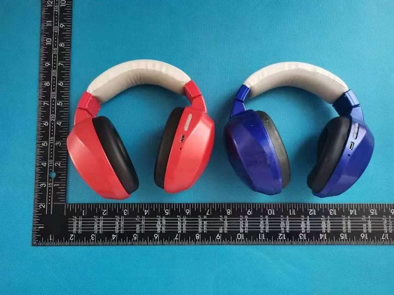
Jun 03, 2021Hearmuff Bluetooth
Equipment Class
DSS - Part 15 Spread Spectrum Transmitter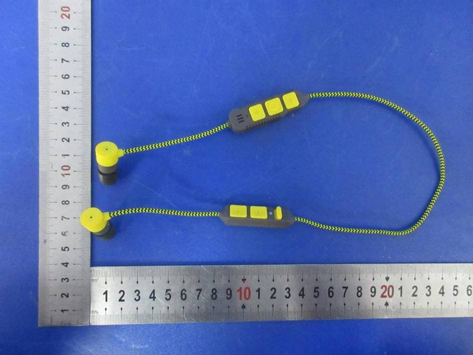
2AU6S-HGBTAMB
Feb 26, 2020Bluetooth earphone with Ambient mode with Bluetooth Transmitter
Equipment Class
DSS - Part 15 Spread Spectrum Transmitter