2AU6S-RRD8400SBHearmuff Bluetooth
LUCID AUDIO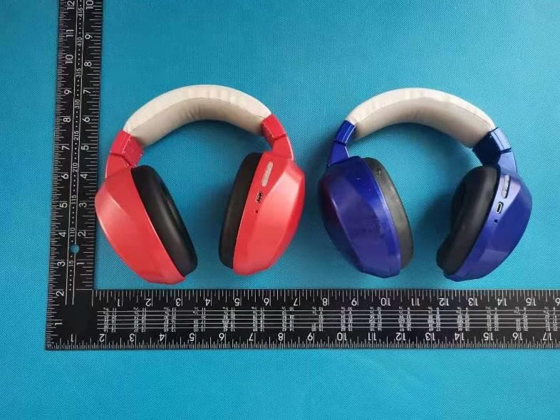
Click to zoom
Application Details
- Equipment Class
- DSS - Part 15 Spread Spectrum Transmitter
- Date of Grant
- Jun 03, 2021
- Application Purpose
- Original Equipment
- Date of Application
- Jun 01, 2021
- Equipment Note
- Hearmuff Bluetooth
- Frequency Range
- 2402.00000000 - 2480.00000000
- Company
- LUCID AUDIO
- Country
- United States
Documents & Files
Document Text
Text extracted from the exhibit documents filed with the FCC. Open a document above to read the original.
Users Manual
1. Volume/Track Up 2. Power button 3. Volume/Track Down 4. USB Charging port 5. LED indicator Light TaskButtonPress Turn onCenter 3 Seconds Turn offCenter 3 Seconds Bluetooth Pairing Center Hold for 6 Seconds Volume Up To pShort Press Volume Down BottomShort Press Track Forward Center Button Press 2 Times Track Back Center Button Press 3 Times Fast User Manual 1 2 3 4 5 B l u e t o o t h Model:BT HEARMUFFS How to use A. Charge: 1. Connect USB charging cable to the headphones and a USB source 2. LED light turns red when charging, and turns off when charged B. Pairing: 1. With headphones turned off press and hold the center button until the LED flashes a rapid blue light and you hear the words “pairing mode.” 2. On your device, turn on the Bluetooth function, and set it to search for Bluetooth devices. 3. Select “BT Hearmuff” from the list of found devices 4. When paired, the LED flashes blue slowly. Note: During pairing, if the headphones are not connected to a device within 5 minutes, they automatically turn off. When successfully paired, your headphones automatically reconnect to the most recently paired device when switched on. NOTE: This equipment has been tested and found to comply with the limits for a Class B digital device, pursuant to part 15 of the FCC Rules. These limits are designed to provide reasonable protection against harmful interference in a residential installation. This equipment generates uses and can radiate radio frequency energy and, if not installed and used in accordance with the instructions, may cause harmful interference to radio communications. However, there is no guarantee that interference will not occur in a particular installation. If this equipment does cause harmful interference to radio or television reception, which can be determined by turning the equipment off and on, the user is encouraged to try to correct the interference by one or more of the following measures: - Reorient or relocate the receiving antenna. - Increase the separation between the equipment and receiver. - Connect the equipment into an outlet on a circuit different from that to which the receiver is connected. - Consult the dealer or an experienced radio/TV technician for help Changes or modifications not expressly approved by the party responsible for compliance could void the user's authority to operate the equipment. This device complies with Part 15 of the FCC Rules. Operation is subject to the following two conditions: (1) this device may not cause harmful interference, and (2) this device must accept any interference received, including interference that may cause undesired operation. The device has been evaluated to meet general RF exposure requirement. The device can be used in portable exposure condition without restriction. RF Exposure Information. HearMuff Bluetooth 0421 - REV A HearMuff Bluetooth 0421 - REV A ISED Statement English: This device complies with Part 15 of the FCC Rules [and contains license-exempt transmitter(s)/receiver(s) that comply with Innovation, Science and Economic Development Canada’s licence-exempt RSS standard(s)]. Operation is subject to the following two conditions: (1)this device may not cause harmful interference, and (2)this device must accept any interference received, including interference that may cause undesired operation. The digital apparatus complies with Canadian CAN ICES‐3 (B)/NMB‐3(B). French: L’émetteur/récepteurexempt de licence contenu dans le présent appareil est conforme aux CNR d’Innovation, Sciences et DéveloppementéconomiqueCanada applicables aux appareils radio exempts de licence. L'exploitation est autorisée aux deux conditions suivantes: (1) l'appareil ne doit pas produire de brouillage, et (2) l'appareil doit accepter tout brouillage radioélectrique subi, même si le brouillage est susceptible d'en compromettre le fonctionnement. l'appareil numérique du ciem conforme canadien peut ‐ 3 (b) / nmb ‐ 3 (b). This device meets the exemption from the routine evaluation limits in section 2.5 of RSS 102 and compliance with RSS 102 RF exposure, users can obtain Canadian information on RF exposure and compliance. cet appareil est conforme à l'exemption des limites d'évaluation courante dans la section 2.5 du cnr - 102 et conformité avec rss 102 de l'exposition aux rf, les utilisateurs peuvent obtenir des données canadiennes sur l'exposition aux champs rf et la conformité. This equipment complies with Canada radiation exposure limits set forth for an uncontrolled environment. Cet équipement est conforme aux limites d'exposition aux rayonnements du Canada établies pour un environnement non contrôlé. RF Exposure Statement The device has been evaluated to meet general RF exposure requirement. The device can be usedin portable exposurecondition without restriction. L'appareil a été évalué pour répondre aux exigences générales d'exposition aux radiofréquences. L'appareil peut être utilisé en condition d'exposition portable sans restriction.
Cover Letter(s)
CONFIDENTIALITY REQUEST for Certification Service in USA Federal Communication Commission Equipment Authorization Division, Application Processing Branch 7435 Oakland Mills Road Columbia, MD 21046 Date:<2021-5-26> Pursuant to Paragraphs §0.457 and 0.459 of the Commission’s Rules (47 C.F.R.) and Section §552(b)(4) of the Freedom of Information Act, we requests confidentiality for the following products: FCC ID Model name 2AU6S-RRD8400SB BT HEARMUFFS For the product stated above, we request that the following information be held confidential; Exhibits Long-Term Confidentiality Short-Term Confidentiality Short-Term Confidentiality Days External Photos Internal Photos Block Diagram Schematics Test Setup Photos User’s Manual Parts List Tune Up Operational Descriptions The long-term confidentiality exhibits contain our trade secrets and proprietary information that could be of benefit to our competitors. The short-term confidentiality on the basis of ensuring that business sensitive information remains confidential until the actual marketing of our new device. If you have any questions, please feel free to contact me at the address shown below. Sincerely, Name/Title: Tal Kocen/MR Company: LUCID AUDIO Address: 14301 Faa Blvd, Ft Worth Texas United States Phone: 646.522.3128 Fax: 646.304.2160 E-Mail: [email protected]
Cover Letter(s)
LUCID AUDIO 14301 Faa Blvd, Ft Worth Texas United States Federal Communications Commission Authorization and Evaluation Division Equipment Authorization Branch 7435 Oakland Mills Road Columbia, MD 21046 2021-5-26 To whom it may concern: We, LUCID AUDIO the undersigned, hereby authorize Eurofins Product Service GmbH to act on our behalf in all matters relating to applications for equipment authorization FCC ID: 2AU6S-RRD8400SB including the signing of all documents related to these matters. Any and all acts carried out by Eurofins Product Service GmbH on our behalf shall have the same effect as acts of our own. We also hereby certify that no party to this application is subject to a denial of benefits, including FCC benefits, pursuant to Section 5301 of the Anti-Drug Abuse Act of 1988, 21 U.S.C. 862. Sincerely, Name/Title: Tal Kocen/MR Company: LUCID AUDIO Address: 14301 Faa Blvd, Ft Worth Texas United States Phone: 646.522.3128 Fax: 646.304.2160 E-Mail: [email protected]
External Photos
FCC ID: 2AU6S-RRD8400SB IC: 25701-RRD8400SB FCC ID: 2AU6S-RRD8400SB IC: 25701-RRD8400SB FCC ID: 2AU6S-RRD8400SB IC: 25701-RRD8400SB
ID Label/Location Info
FCC ID: 2AU6S-RRD8400SB IC: 25701-RRD8400SB FCC ID: 2AU6S-RRD8400SB IC: 25701-RRD8400SB Model(HVIN): BT HEARMUFFS
Internal Photos
FCC ID: 2AU6S-RRD8400SB IC: 25701-RRD8400SB Antenna FCC ID: 2AU6S-RRD8400SB IC: 25701-RRD8400SB
RF Exposure Info
RF Exposure evaluation FCC ID: 2AU6S-RRD8400SB 1.1. Applicable Standard According to §1.1307(b)(1), systems operating under the provisions of this section shall be operated in a manner that ensures that the public is not exposed to radio frequency energy level in excess of the Commission’s guidelines. According to §1.1310 and §2.1093 RF exposure requirement KDB447498 v06: Mobile and Portable Devices RF Exposure Procedures and Equipment Authorization Policies 1.2. Requirement According to KDB447498 D01 General RF Exposure Guidance v06 Section 4.3.1 Standalone SAR test exclusion considerations: “Unless specifically required by the published RF exposure KDB procedures, standalone 1-g head or body and 10-g extremity SAR evaluation for general population exposure conditions, by measurement or numerical simulation, is not required when the corresponding SAR Test Exclusion Threshold condition, listed below, is satisfied. These test exclusion conditions are based on source-based time-averaged maximum conducted output power of the RF channel requiring evaluation, adjusted for tune-up tolerance, and the minimum test separation distance required for the exposure conditions.22 The minimum test separation distance is determined by the smallest distance from the antenna and radiating structures or outer surface of the device, according to the host form factor, exposure conditions and platform requirements, to any part of the body or extremity of a user or bystander (see 5) of section 4.1). To qualify for SAR test exclusion, the test separation distances applied must be fully explained and justified by the operating configurations and exposure conditions of the transmitter and applicable host platform requirements, typically in the SAR measurement or SAR analysis report, according to the required published RF exposure KDB procedures. When no other RF exposure testing or reporting is required, a statement of justification and compliance must be included in the equipment approval, in lieu of the SAR report, to qualify for the SAR test exclusion. When required, the device specific conditions described in the other published RF exposure KDB procedures must be satisfied before applying these SAR test exclusion provisions; for example, handheld PTT two-way radios, handsets, laptops & tablets etc.23 “ [(max. power of channel, including tune-up tolerance, mW)/ (min. test separation distance, mm)] · [√f (GHz)] ≤ 3.0 for 1-g SAR and ≤ 7.5 for 10-g extremity SAR, where: • f (GHz) is the RF channel transmit frequency in GHz • Power and distance are rounded to the nearest mW and mm before calculation • The result is rounded to one decimal place for comparison • 3.0 and 7.5 are referred to as the numeric thresholds in the step 2 below The test exclusions are applicable only when the minimum test separation distance is ≤ 50 mm and for transmission frequencies between 100 MHz and 6 GHz. When the minimum test separation distance is < 5 mm, a distance of 5 mm according to 5) in section 4.1 is applied to determine SAR test exclusion. 1.3. Manufacturing tolerance GFSK(Peak) Channel Channel 00 Channel 39 Channel 78 Target (dBm) 0.0 0.0 0.0 Tolerance ±(dB) 1.0 1.0 1.0 π/4DQPSK(Peak) Channel Channel 00 Channel 39 Channel 78 Target (dBm) 0.0 0.0 0.0 Tolerance ±(dB) 1.0 1.0 1.0 8DPSK(Peak) Channel Channel 00 Channel 39 Channel 78 Target (dBm) 0.0 0.0 0.0 Tolerance ±(dB) 1.0 1.0 1.0 2. E v a l u a t i o n R e s u l t Evaluation Results Band/Mode f (GHz) Antenna Distance (mm) RF output power (including tune-up tolerance) SAR Test Exclusion Threshold SAR Test Exclusion dBm mW BT 2.402 5 1 1.259 0.4<3.0 Yes 3. C o n c l u s i o n The measurement results comply with the FCC Limit per 47 CFR 2.1093 for the uncontrolled RF Exposure and SAR Exclusion Threshold per KDB 447498 v06, No SAR is required. .....................End.........................
Test Report
Shenzhen Global Test Service Co.,Ltd. No.7-101 and 8A-104, Building 7 and 8, DCC Cultural and Creative Garden, No.98, Pingxin North Road, Shangmugu Community, Pinghu Street, Longgang District, Shenzhen, Guangdong TEST REPORT FCC PART 15 SUBPART C 15.247 & RSS-247 Report Reference No. ..................... : FCC ID ............................................. : GTS20210531015-1-1 2AU6S-RRD8400SB IC ..................................................... : 25701-RRD8400SB Compiled by ( position+printed name+signature) .. : File administrators Jimmy Wang Supervised by ( position+printed name+signature) .. : Test Engineer Aaron Tan Approved by ( position+printed name+signature) .. : Manager Jason Hu Date of issue ..................................... : May 20, 2021 Representative Laboratory Name .: Shenzhen Global Test Service Co., Ltd. No.7-101 and 8A-104, Building 7 and 8, DCC Cultural and Creative Garden, No.98, Pingxin North Road, Shangmugu Community, Pinghu Street, Longgang District, Shenzhen, Guangdong ............................ : LUCID AUDIO Address ............................................ : 14301 Faa Blvd, Ft Worth, TX 76155 United States of America Test specification ...........................: Standard ........................................... : 47 CFR FCC Part 15 Subpart C 15.247 & RSS-247 Issue 2, February 2017 TRF Originator .................................. : Shenzhen Global Test Service Co.,Ltd. Master TRF ....................................... : Dated 2014-12 Shenzhen Global Test Service Co.,Ltd. All rights reserved. This publication may be reproduced in whole or in part for non-commercial purposes as long as the Shenzhen Global Test Service Co.,Ltd. is acknowledged as copyright owner and source of the material. Shenzhen Global Test Service Co.,Ltd. takes no responsibility for and will not assume liability for damages resulting from the reader's interpretation of the reproduced material due to its placement and context. Test item description .....................: Hearmuff Bluetooth Trade Mark ....................................... : Lucid Manufacturer ................................... : LUCID AUDIO Model/Type reference(HVIN) ........... : BT HEARMUFFS Listed Models(HVIN) ....................... : N/A Ratings ............................................. : DC 3.7V from battery Modulation ....................................... : Hardware version ............................. : RRD-8400S-B V1.1 Software version .............................. : V1.0 Test Software version ...................... : V1.0.2.2 Frequency ......................................... : From 2402MHz to 2480MHz Result................................................ : PASS Report No.: GTS20210531015-1-1 Page 2 of 52 T E S T R E P O R T Test Report No. : GTS20210531015-1-1 May 31, 2021 ____________________________________________________________________________________ Date of issue Equipment under Test : Hearmuff Bluetooth Model /Type(HVIN) : BT HEARMUFFS Listed Models(HVIN) : N/A Applicant : LUCID AUDIO Address : 14301 Faa Blvd, Ft Worth, TX 76155 United States of America Manufacturer : LUCID AUDIO Address : 14301 Faa Blvd, Ft Worth, TX 76155 United States of America Test Result : PASS The test report merely corresponds to the test sample. It is not permitted to copy extracts of these test result without the written permission of the test laboratory. Report No.: GTS20210531015-1-1 Page 3 of 52 Contents 1T EST ST A N D A RD S ................................................................. 4 2SU MMA R Y ............................................................................ 5 2.1General Remarks 5 2.2Product Description 5 2.3Test Sample 5 2.4Equipment Under Test 5 2.5Short description of the Equipment under Test (EUT) 5 2.6EUT operation mode 6 2.7Block Diagram of Test Setup 6 2.8Special Accessories 6 2.9Related Submittal(s) / Grant (s) 6 2.10Modifications 6 3T EST EN VIR O N MEN T .............................................................. 7 3.1Address of the test laboratory 7 3.2Test Facility 7 3.3Environmental conditions 7 3.4Summary of measurement results 8 3.5Statement of the measurement uncertainty 8 3.6Equipments Used during the Test 9 4T EST C O N DIT IO N S A N D R ESU L T S ........................................... 10 4.1AC Power Conducted Emission 10 4.2Radiated Emission 13 4.3Maximum Peak Output Power 20 4.420dB Bandwidth 21 4.599% Occupied Bandwidth 25 4.6Frequency Separation 29 4.7Number of hopping frequency 31 4.8Time of Occupancy (Dwell Time) 33 4.9Out-of-band Emissions 37 4.10Pseudorandom Frequency Hopping Sequence 45 4.11Antenna Requirement 46 5T EST SET U P PH O TO S O F T H E EU T ......................................... 47 6PH O T O S O F T H E EU T ........................................................... 48 Report No.: GTS20210531015-1-1 Page 4 of 52 1 TEST ST ANDAR D S The tests were performed according to following standards: RSS-247-Issue 2: Digital Transmission Systems (DTSs), Frequency Hopping Systems (FHSs) and Licence- Exempt Local Area Network (LE-LAN) Devices. RSS-Gen Issue 5: General Requirements for Compliance of Radio Apparatus FCC Rules Part 15.247: Frequency Hopping, Direct Spread Spectrum and Hybrid Systems that are in operation within the bands of 902-928 MHz, 2400-2483.5 MHz, and 5725-5850 MHz. ANSI C63.10-2013: American National Standard for Testing Unlicensed Wireless Devices Report No.: GTS20210531015-1-1 Page 5 of 52 2 SUMM AR Y 2.1 General Remarks Date of receipt of test sample : Apr. 28, 2021 Testing commenced on : Apr. 29, 2021 Testing concluded on : May 14, 2021 2.2 Product Description Product Name: Hearmuff Bluetooth Model(HVIN): BT HEARMUFFS Power supply: DC 3.7V from battery Sample ID: GTS20210531015-1-1#/ GTS20210531015-1-2# Bluetooth : Supported Type: Bluetooth BR/EDR Modulation: GFSK, /4DQPSK, 8DPSK Operation frequency: 2402MHz~2480MHz Channel number: 79 Channel separation: 1MHz Antenna type: PCB antenna Antenna gain: 0 dBi 2.3 Tes…
Text truncated - open the document above for the full version.
Test Report
Report No.: GTS20210531015-1-1 Page 38 of 52 GFSK CH00 GFSK CH39 Reference Reference 30MHz-3GHz 30MHz-3GHz 3GHz-25GHz 3GHz-25GHz Report No.: GTS20210531015-1-1 Page 39 of 52 GFSK CH78 /4DQPSK CH01 Reference Reference 30MHz-3GHz 30MHz-3GHz 3GHz-25GHz 3GHz-25GHz Report No.: GTS20210531015-1-1 Page 40 of 52 /4DQPSK CH39 /4DQPSK CH78 Reference Reference 30MHz-3GHz 30MHz-3GHz 3GHz-25GHz 3GHz-25GHz Report No.: GTS20210531015-1-1 Page 41 of 52 8DPSK CH00 8DPSK CH39 Reference Reference 30MHz-3GHz 30MHz-3GHz 3GHz-25GHz 3GHz-25GHz Report No.: GTS20210531015-1-1 Page 42 of 52 8DPSK CH78 Reference 30MHz-3GHz 3GHz-25GHz Report No.: GTS20210531015-1-1 Page 43 of 52 Band-edge Measurements for RF Conducted Emissions: GFSK Left Band edge hoping off Right Band edge hoping off Left Band edge hoping on Right Band edge hoping on /4DQPSK Left Band edge hoping off Right Band edge hoping off Report No.: GTS20210531015-1-1 Page 44 of 52 Left Band edge hoping on Right Band edge hoping on 8DPSK Left Band edge hoping off Right Band edge hoping off Left Band edge hoping on Right Band edge hoping on Report No.: GTS20210531015-1-1 Page 45 of 52 4.10 Pseudorandom Frequency Hopping Sequence TEST APPLICABLE For 47 CFR Part 15C section 15.247 (a) (1) requirement: Frequency hopping systems shall have hopping channel carrier frequencies separated by a minimum of 25 kHz or the 20 dB bandwidth of the hop-ping channel, whichever is greater. Alternatively, frequency hopping systems operating in the 24002483.5 MHz band may have hopping channel carrier frequencies that are separated by 25 kHz or two-thirds of the 20 dB bandwidth of the hopping channel, whichever is greater, provided the systems operate with an output power no greater than 125 mW. The system shall hop to channel frequencies that are selected at the system hopping rate from a pseudo randomly ordered list of hopping frequencies. Each frequency must be used equally on the average by each transmitter. The system receivers shall have input bandwidths that match the hop-ping channel bandwidths of their corresponding transmitters and shall shift frequencies in synchronization with the transmitted signals. EUT Pseudorandom Frequency Hopping Sequence Requirement The pseudorandom frequency hopping sequence may be generated in a nice-stage shift register whose 5 th and 9 th stage outputs are added in a modulo-two addition stage. And the result is fed back to the input of the first stage. The sequence begins with the first one of 9 consecutive ones, for example: the shift register is initialized with nine ones. Number of shift register stages:9 Length of pseudo-random sequence:29-1=511 bits Longest sequence of zeros:8(non-inverted signal) An example of pseudorandom frequency hopping sequence as follows: Each frequency used equally one the average by each transmitter. The system receiver have input bandwidths that match the hopping channel bandwidths of their corresponding transmitter and shift frequencies in synchronization with the transmitted signals. Report No.: GTS20210531015-1-1 Page 46 of 52 4.11 Antenna Requirement Standard Applicable For intentional device, according to FCC 47 CFR Section 15.203, an intentional radiator shall be designed to ensure that no antenna other than that furnished by the responsible party shall be used with the device. And according to FCC 47 CFR Section 15.247 (c), if transmitting antennas of directional gain greater than 6dBi are used, the power shall be reduced by the amount in dB that the directional gain of the antenna exceeds 6dBi. Refer to statement below for compliance The manufacturer may design the unit so that the user can replace a broken antenna, but the use of a standard antenna jack or electrical connector is prohibited. Further, this requirement does not apply to intentional radiators that must be professionally installed. Antenna Connected Construction The maximum gain of antenna was 0dBi. Report No.: GTS20210531015-1-1 Page 47 of 52 5 T est Setup Ph ot o s o f t h e EUT Report No.: GTS20210531015-1-1 Page 48 of 52 6 Pho to s o f the EU T External photos Report No.: GTS20210531015-1-1 Page 49 of 52 Report No.: GTS20210531015-1-1 Page 50 of 52 Report No.: GTS20210531015-1-1 Page 51 of 52 Internal photos Report No.: GTS20210531015-1-1 Page 52 of 52 ********************** End of Report **********************
Test Setup Photos
FCC ID: 2AU6S-RRD8400SB IC: 25701-RRD8400SB
Contact Information
Applicant
Tal Kocen(MR)
Test Firm
Shenzhen Global Test Service Co., Ltd.Simon Hu
[email protected]86-137-286-828-40
Technical Specifications
| # | Rule Parts | Frequency Range | Power Output |
|---|---|---|---|
| 1 | 15C | 2.40 GHz - 2.48 GHz | 1.10 mW |
Other Applications from LUCID AUDIO
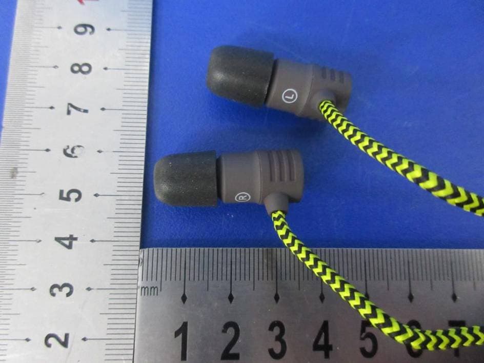
2AU6S-HGBT
Feb 26, 2020Bluetooth earphone with Bluetooth Transmitter
Equipment Class
DSS - Part 15 Spread Spectrum Transmitter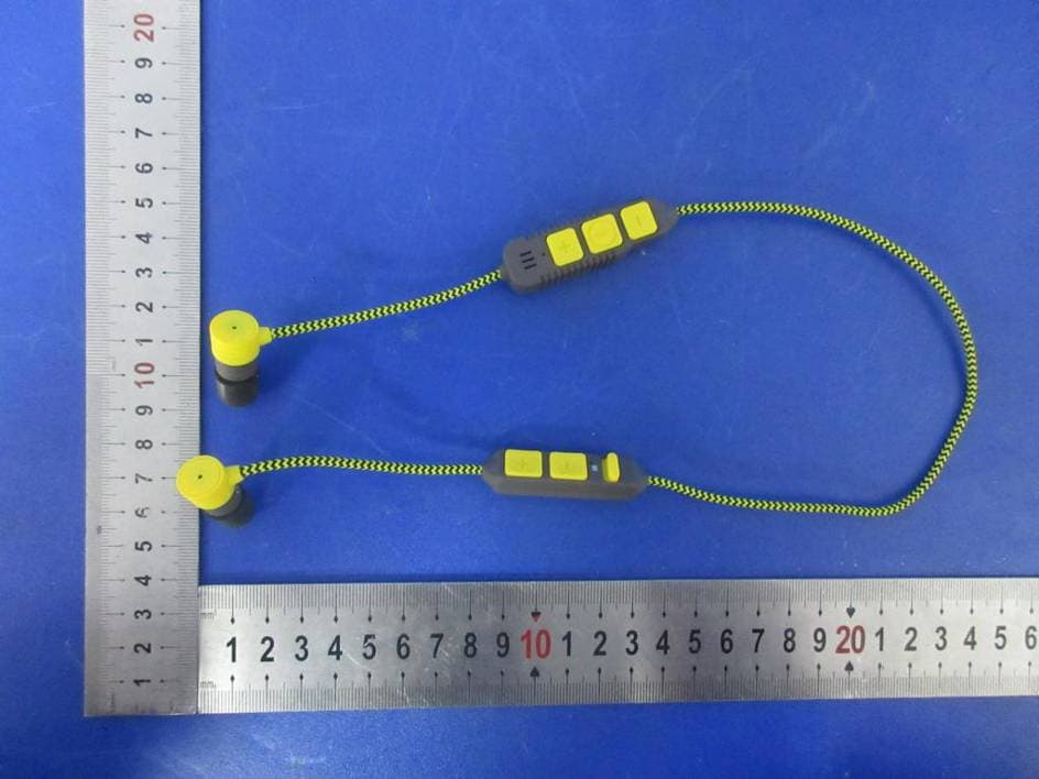
2AU6S-HGBTAMB
Feb 26, 2020Bluetooth earphone with Ambient mode with Bluetooth Transmitter
Equipment Class
DSS - Part 15 Spread Spectrum Transmitter