2AU7D-PODIUMAPODIUM 3-IN-1 WIRELESS CHARGER
PYS High-Tech Co., LTD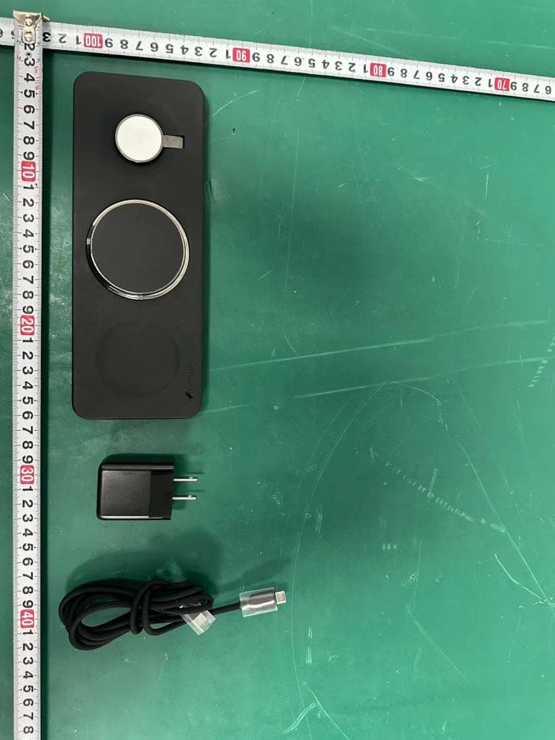
Click to zoom
Application Details
- Equipment Class
- DCD - Part 15 Low Power Transmitter Below 1705 kHz
- Date of Grant
- Sep 04, 2024
- Application Purpose
- Original Equipment
- Date of Application
- Sep 04, 2024
- Equipment Note
- PODIUM 3-IN-1 WIRELESS CHARGER
- Frequency Range
- 0.36000000 - 0.36000000
- Company
- PYS High-Tech Co., LTD
- Country
- China
Documents & Files
Document Text
Text extracted from the exhibit documents filed with the FCC. Open a document above to read the original.
Users Manual
Charging Instructions: 1. Connect USB-C Cable to Wireless charger and Wall Adapter. 2. Plug Wall Adapter into wall outlet. 3. Adjust hinges to desired position and start charging. Note: Always connect to power using a Nimble USB-C Wall Charger, for the safest, most e icient charging experience. Other Wall Chargers will work but the output should be at least 35W. Instructions de Chargement: 1. Connectez le câble USB-C au chargeur sans fil et à l'adaptateur mural. 2. Branchez l'adaptateur mural dans une prise de courant. 3. Ajustez les charnières à la position souhaitée et commencez à charger. Remarque : Connectez toujours à l'alimentation en utilisant un chargeur mural USB-C Nimble pour une expérience de charge la plus sûre et la plus e icace. D'autres chargeurs muraux fonctionneront, mais la puissance de sortie devrait être d'au moins 35W. Charging Apple Watch: Charge laying flat or lift hinge to charge in Nightstand Mode. Chargement de l'Apple Watch: Chargez-la à plat ou soulevez la charnière pour charger en mode Table de nuit. Charging iPhone: Charge laying flat or lift hinge to use as a stand or charge in Nightstand Mode. Chargement de l'iPhone: Chargez-le à plat ou soulevez la charnière pour l'utiliser comme support ou pour charger en mode Table de nuit. Charge 3 devices at the same time. Chargez 3 appareils en même temps. gonimble.com/FAQs gonimble.com/pages/global-compliance EN IMPORTANT SAFETY INSTRUCTIONS Warning: Read all instructions and warnings prior to using this product. Improper use of this product may result in product damage, excess heat, toxic fumes, fire or explosion, for which damages you ("Purchaser"), and not Nimble for Good, PBC. ("Manufacturer") are responsible. • Do not store device in high-temperature environment, including heat caused by intense sunlight or other forms of heat. Do not place device in fire or other excessively hot environments. Exposure to fire or temperature above 212°F (100°C) may cause explosion. • Do not expose the wireless charger to rain or snow. • Do not use the wireless charger in excess of its output rating. Overloading outputs above rating may result in a risk of fire or injury to persons. • Do not disassemble this product or attempt to re-purpose or modify it in any manner. • Do not attempt to replace any part of this device. • Use of a power supply or charger not recommended by Nimble may result in a risk of fire or injury to persons. • If this device is accessible to, or may be used by a minor, purchasing adult agrees to be solely responsible for providing supervision, instruction, and warnings. Purchaser agrees to defend, indemnify, and hold Manufacturer harmless for any claims or damages arising from unintended use or misuse by a minor. • All products have gone through a thorough quality assurance inspection. If you find that your device is excessively hot, is emitting odor, is deformed, abraded, cut, or is experiencing or demonstrating an abnormal phenomenon, immediately stop all product use and contact Manufacturer. • Switch off the wireless charger when not in use. The wireless charger will automatically switch off when disconnected from its wall charger. • To disconnect the charging pad from line voltage, pull the AC adapter from the AC outlet. • The AC outlet shall be installed near the charging pad and shall be easily accessible. • To comply with FCC RF exposure compliance requirements, the wireless charger must be used with a separation distance of at least 20 cm from all persons. •To comply with IC RF exposure compliance requirements, the wireless charger must be used with a separation distance of at least 10 cm from all persons. SAVE THESE INSTRUCTIONS Legal: Manufacturer shall not in any way be liable to you or to any third party for any damages you or any third party may suffer as a result of use, intended or unintended, or misuse of this product in conjunction with any device or accessory other than the appropriate device for which this product is designed. Manufacturer will not be responsible for any damages you or any third party may suffer as a result of misuse of this product as outlined above. Purchaser agrees to defend, indemnify, and hold Manufacturer harmless for any claims or damages arising from unintended use or misuse, including use with an unintended device. This device complies with part 15 of the FCC Rules and RSS-Gen of IC Rules. Operation is subject to the following two conditions: (1) This device may not cause harmful interference, and (2) this device must accept any interference received, including interference that may cause undesired operation. NOTE: This equipment has been tested and found to comply with the limits for a Class B digital device, pursuant to part 15 of the FCC Rules. These limits are designed to provide reasonable protection against harmful interference in a residential installation. This equipment generates, uses, and can radiate radio frequency energy and, if not installed and used in accordance with the instructions, may cause harmful interference to radio communications. However, there is no guarantee that interference will not occur in a particular installation. If this equipment does cause harmful interference to radio or television reception, which can be determined by turning the equipment off and on, the user is encouraged to try to correct the interference by one or more of the following measures: • Reorient or relocate the receiving antenna. • Increase the separation between the equipment and receiver. • Connect the equipment into an outlet on a circuit different from that to which the receiver is connected. • Consult the dealer or an experienced radio/TV technician for help. CAUTION: To comply with the limits of the Class B digital device, pursuant to Part 15 of the FCC Rules, this device must be used with certified peripherals and shielded cables. All peripherals must be shielded and grounded. Operation with non-certified peripherals or non-shielded cables may result in…
Text truncated - open the document above for the full version.
Attestation Statements
PYS High-Tech Co., Ltd Federal Communications Commission Authorization and Evaluation Division 7435 Oakland Mills Road Columbia, MD 21046 USA Date:08-24-2024 FCC ID: 2AU7D-PODIUMA Ref. #1: Attestation Statements Part 2.911(d)(5)(i) Filing PYS High-Tech Co., Ltd certifies that the equipment for which authorization is sought is not “covered” equipment prohibited from receiving an equipment authorization pursuant to section 2.903 of the FCC rules. Ref. #2: Attestation Statements Part 2.911(d)(5)(ii) Filing PYS High-Tech Co., Ltd certifies that, as of the date of the filing of the application, the applicant is not identified on the Covered List (as a specifically named entity or any of its subsidiaries or affiliates)as an entity producing “covered” equipment. Applicant: PYS High-Tech Co., Ltd Address: 1F~12F, Block 9, Lianhua Industrial Zone, Longhua Shenzhen 518109, China Contact Person: Alan Xiang Tel.: 0755-28130218 Email: [email protected] Sincerely, Signature:
Attestation Statements
PYS High-Tech Co., Ltd * the applicant must designate a contact located in the United States for purposes of acting as the applicant’s agent for service of process, regardless of whether the applicant is a domestic or foreign entity. An applicant located in the United States may designate itself as the agent for service of process. U.S. Agent Designation for Service of Process - Certification Attestation Letter 8/24/2024 Federal Communications Commission Authorization and Evaluation Division 7435 Oakland Mills Road Columbia, MD 21046 USA ATTN.: Reviewing Engineer FCC ID: 2AU7D-PODIUMA Applicant of FRN: 0028998433 Per section 2.911(d)(7) of the FCC rules, PYS High-Tech Co., Ltd (“the applicant”) certifies that the equipment for which authorization is sought is designated to the following U.S. agent* for service of process: Company Name: NIMBLE FOR GOOD, PBC. FCC Registration Number (FRN): 0030768691 Physical U.S. Company Address: 3195 RED HILLAVE., LOFT F, 2ND FLOOR, COSTA MESA, CA 92626 COSTA MESA,CA 92626 United States Contact Person: Julie Kao Agent Email Address: [email protected] The above contact person accepts the obligation for service of process. The applicant accepts to maintain an agent for no less than one year after the grantee has terminated all marketing and importation or the conclusion of any Commission-related proceeding involving the equipment. Applicant Signed: Agent Signed (if different to Applicant): Signed: Signed: Printed name: Alan Xiang Printed name: Julie Kao Title: Electronics Engineer Title:Product manager Company Name: PYS High-Tech Co., Ltd Company Name: NIMBLE FOR GOOD, PBC. Date: 8/24/2024 Date: 8/24/2024
Cover Letter(s)
manufacturer:SINYOTechnology(Dongguan)co., Ltd. address:3F, No. 37 South West Lake Second Road, Shilong Town, Dongguan City model:SINYO MP-A11-20
Cover Letter(s)
manufacturer:SINYOTechnology(Dongguan)co., Ltd. address:3F, No. 37 South West Lake Second Road, Shilong Town, Dongguan City model:SINYO MPP-TX-14
Cover Letter(s)
Manufacture/factory:apple inc Address: One Apple Park Way, Cupertino, California, United States Diameter:28.79mm Thickness:6.23mm
Cover Letter(s)
PYS High-Tech Co., Ltd Date:8/30/2024 Product Model Number: NB-WP-3N1TRY FCC ID:2AU7D-PODIUMA To whom it may concern, Re: Product Certification Representative Authorization Letter We authorize QAI Laboratories Ltd. 3980 North Fraser Way, Burnaby B.C. Canada V5J 5K5 to act on our behalf on all matters concerning the above named equipment. This shall include the following: Testing Approval applications and procedures We declare that ORGANIZATION. is allowed to forward all information related to the approval project to the applied certification body and to the notification entities and to discuss any issues concerning the approval application. Any and all acts carried out by ORGANIZATION. on our behalf shall have the same effect as acts of our own. By: Contact Listed on FCC Wesbite Signature: Name: Alan Xiang Title: Electronics Engineer Email: [email protected] Telephone: 0755-28130218 On behalf of: PYS High-Tech Co., Ltd
Cover Letter(s)
PYS High-Tech Co., Ltd Office of Engineering Technology Federal Communications Commission 7435 Oakland Mills Road Columbia, MD 21046 USA Date: September 3, 2024 Subject; Request for Confidentiality FCC ID: 2AU7D-PODIUMA To Whom It May Concern, Pursuant to the provisions of the Commission’s rules Title 47 Sections §0.457 and §0.459, we are requesting the Commission to withhold the following attachment(s) as confidential documents from public disclosure indefinitely. These documents contain detailed system and equipment descriptions and are considered as proprietary information in operation of the equipment. The public disclosure of these documents might be harmful to our company and would give competitors an unfair advantage in the market. Schematic Diagram Block Diagram Parts List Operational Description Tune-up Procedure Software Security Requirements for UNII devices In additional to above mentioned documents, in order to comply with the marketing regulations in Title 47 CFR §2.803 and the importation rules in Title 47 CFR §2.1204, while ensuring that business sensitive information remains confidential until the actual marketing of newly authorized devices, we request Short Term Confidentiality of the following attachment(s); External Photos Test Setup Photos Internal Photos User Manual For 45 days, pursuant to Public Notice DA 04-1705. OR For 180 days pursuant to KDB 726920 D01. It is our understanding that all measurement test reports, FCC ID label format and correspondence during the certification review process cannot be granted as confidential documents and this information will be available for public review once the grant of equipment authorization is issued. Sincerely, Signature: Name: Alan Xiang Title:Electronics Engineer
Cover Letter(s)
PYS High-Tech Co., Ltd Covered Equipment Certification Attestation Letter Federal Communications Commission Authorization and Evaluation Division 7435 Oakland Mills Road Columbia, MD 21046 USA ATTN.: Reviewing Engineer FCC ID: 2AU7D-PODIUMA PYS High-Tech Co., Ltd is not identified on the Covered List (as a specifically named entity or any of its subsidiaries or affiliates) as an entity producing “covered” equipment. Signed: Printed name: Alan Xiang Title: Electronics Engineer Company Name: PYS High-Tech Co., Ltd Date: 8/24/2024
External Photos
External Photos M/N: NB-WP-3N1TRY External Photos M/N: NB-WP-3N1TRY External Photos M/N: NB-WP-3N1TRY External Photos M/N: NB-WP-3N1TRY External Photos M/N: NB-WP-3N1TRY
Internal Photos
Internal Photos M/N: NB-WP-3N1TRY Internal Photos M/N: NB-WP-3N1TRY Airpods Coil Internal Photos M/N: NB-WP-3N1TRY Phone Coil Internal Photos M/N: NB-WP-3N1TRY Watch Coil
RF Exposure Info
Page 1 of 6 Report No. ESTE-R2408118 FCC 47 CFR MPE REPORT PYS High-Tech Co., Ltd. PODIUM 3-IN-1 WIRELESS CHARGER Model Number: NB-WP-3N1TRY FCC ID: 2AU7D-PODIUMA Applicant: PYS High-Tech Co., Ltd. Address: 1F~12F, Block 9, Lianhua Industrial Zone, Longhua, Shenzhen 518109, China Prepared By: EST Technology Co., Ltd. Chilingxiang, Qishantou, Santun, Houjie, Dongguan, Guangdong, China Tel: 86-769-83081888-808 Report Number: ESTE-R2408118 Date of Test: Aug. 03, 2024~ Aug. 21, 2024 Date of Report: Aug. 22, 2024 Page 3 of 6 Report No. ESTE-R2408118 1. Summary of test 1.1. Summary of test result No. Description of Test Item FCC Standard Section Results 1 Maximum Permissible Exposure Part 1.1307(b)&1.1310 PASS 1.2. Test Mode 1.3. Test Equipment List Equipment Manufacturer Model No. Serial No. Last Cal. Next Cal. Electric and Magnetic Field Probe-Analyzer Narda S.T.S./PMM EHP-200A EST-E106 June 13,24 1 Year Test Software Narda EHP200-T S Rel 1.92 N/A N/A Note: Test uncertainty: ±1.62 dB (H-field);±1.64 dB (E-field) at a level of confidence of 95%. 1.4. Assistant equipment used for test Item Equipment Brand Model Name/Type No. FCC ID Series No. 1 Adapter - HKAP3891B-36US - - 2 Airpods - A1938 - - 3 iWatch - A2859 - - 4 Phone - A3108 - - Item Shielded Type Ferrite Core Length Model Name/Type No. Note Test Item Test Mode Maximum Permissible Exposure Phone: 15W+Airpods 5W+iWatch 3.5W Full load Half load No load Phone: 15W Full load Half load Airpods 5W Full load Half load iWatch 3.5W Full load Half load Note: All mode have been tested, only the worst case 15W+ 5W+ 3.5W full load test data record in the report. Page 4 of 6 Report No. ESTE-R2408118 1 NO NO 1.5m - DC Cable 2. Maximum Permissible Exposure 2.1. Limit Limits for Maximum Permissible Exposure (MPE) Frequency range (MHz) Electric field strength (V/m) Magnetic field strength (A/m) Power density (mW/cm2) Averaging time (minutes) (A) Limits for Occupational/Controlled Exposure 0.3-3.0 614 1.63 *100 6 3.0-30 1842/f 4.89/f *900/f 2 6 30-300 61.4 0.163 1.0 6 300-1,500 f/300 6 1,500-100,000 5 6 (B) Limits for General Population/Uncontrolled Exposure 0.3-1.34 614 1.63 *100 30 1.34-30 824/f 2.19/f *180/f 2 30 30-300 27.5 0.073 0.2 30 300-1,500 f/1500 30 1,500-100,000 1.0 30 Note:f = frequency in MHz * = Plane-wave equivalent power density. 2.2. Test Setup Page 5 of 6 Report No. ESTE-R2408118 2.3. Test Procedure a. The test was performed on 360 degree turn table in anechoic chamber. b. The probe was placed at 20 cm surrounding, for test setup. c. The highest emission level was recorded and compared with limit as soon as measurement of each point; A, B, C, D, E were completed. 2.4. Equipment Approval Considerations Inductive wireless power transfer applications with supporting field strength results and meeting all of the following requirements are not required to submit a KDB inquiry for devices approved using SDoC or a PAG for equipment approved using certification to address RF exposure compliance. 1 Power transfer frequency is less than 4 MHz YES; the device operated in the frequency range from 110.5-205;326.5;360. 2 Output power from each primary coil is less than or equal to 15 watts YES; the maximum output power of the primary coil is 15W. 3 The system may consist of more than one source primary coils, charging one or more clients. If more than one primary coil is present, the coil pairs may be powered on at the same time. YES; The EUT has three source primary coils 4 Client device is placed directly in contact with the transmitter. YES; Client device is placed directly in contact with the transmitter. 5 Mobile exposure conditions only (portable exposure conditions are not covered by this exclusion). YES; Mobile exposure conditions only. 6 The aggregate H-field strengths anywhere at or beyond 20 cm surrounding the device, and 20 cm away from the surface from all coils that by design can simultaneously transmit, and while those coils are simultaneously energized, are demonstrated to be less than 50% of the applicable MPE limit. YES; The EUT field strength levels are 50% x MPE limts. Page 6 of 6 Report No. ESTE-R2408118 2.5. Test Result for Test setup : E-field strength Test Direction Measuring Distance Test Frequency 110.5-205KHz 326.5KHz 360KHz Position A(V/m) 20cm 0.838 0.335 1.108 Position B(V/m) 20cm 0.954 0.487 1.138 Position C(V/m) 20cm 0.910 0.624 1.064 Position D(V/m) 20cm 0.591 0.541 1.224 Position E(V/m) 20cm 0.857 0.426 1.357 Limits (V/m) 614 H-field strength Test Direction Measuring Distance Test Frequency 110.5-205KHz 326.5KHz 360KHz Position A(A/m) 20cm 0.053 0.048 0.051 Position B(A/m) 20cm 0.056 0.051 0.049 Position C(A/m) 20cm 0.067 0.046 0.050 Position D(A/m) 20cm 0.048 0.054 0.063 Position E(A/m) 20cm 0.057 0.048 0.049 Limits (A/m) 1.630 3. Test photo Position E End of Test Report
Test Report
Page 1 of 46 Report No. ESTE-R2408117 FCC PART 15C TEST REPORT FOR CERTIFICATION On Behalf of PYS High-Tech Co., Ltd. PODIUM 3-IN-1 WIRELESS CHARGER Model Number: NB-WP-3N1TRY FCC ID: 2AU7D-PODIUMA Applicant: PYS High-Tech Co., Ltd. Address: 1F~12F, Block 9, Lianhua Industrial Zone, Longhua, Shenzhen 518109, China Prepared By: EST Technology Co., Ltd. Chilingxiang, Qishantou, Santun, Houjie, Dongguan, Guangdong, China Tel: 86-769-83081888-808 Report Number: ESTE-R2408117 Date of Test: Aug. 03, 2024~ Aug. 21, 2024 Date of Report: Aug. 22, 2024 Page 2 of 46 Report No. ESTE-R2408117 TABLE OF CONTENTS Description Page TEST REPORT VERIFICATION .......................................................................................................... 3 1. GENERAL INFORMATION ................................................................................................................ 4 1.1. Description of Device (EUT) ......................................................................................................... 4 2. SUMMARY OF TEST ........................................................................................................................ 5 2.1. Summary of test result .................................................................................................................. 5 2.2. Test Facilities .................................................................................................................................. 6 2.3. Measurement uncertainty ............................................................................................................. 7 2.4. Assistant equipment used for test ............................................................................................... 7 2.5. Block Diagram ................................................................................................................................ 7 2.6. The test mode was selected for the final test as listed below. ................................................ 8 2.7. Test Equipment List ....................................................................................................................... 9 3. RADIATED EMISSION ................................................................................................................... 10 3.1. Limit ................................................................................................................................................ 10 3.2. Test Setup ..................................................................................................................................... 11 3.3. Spectrum Analyzer Setting ......................................................................................................... 12 3.4. Test Procedure ............................................................................................................................. 12 3.5. Test Result .................................................................................................................................... 14 4. AC POWER LINE CONDUCTED EMISSIONS ................................................................................. 32 4.1. Limit ................................................................................................................................................ 32 4.2. Test Setup ..................................................................................................................................... 32 4.3. Spectrum Analyzer Setting ......................................................................................................... 32 4.4. Test Procedure ............................................................................................................................. 32 4.5. Test Result .................................................................................................................................... 33 5. ANTENNA REQUIREMENTS .......................................................................................................... 35 5.1. Limit ................................................................................................................................................ 35 5.2. Test Result .................................................................................................................................... 35 6. TEST SETUP PHOTO .............................................................................................................. 36 7. EUT PHOTO .............................................................................................................................. 38 Page 4 of 46 Report No. ESTE-R2408117 1. GENERAL INFORMATION 1.1. Description of Device (EUT) Note: For a more detailed features description, please refer to the manufacturer’s specifications or the user's manual. Product Name : PODIUM 3-IN-1 WIRELESS CHARGER Model Number : NB-WP-3N1TRY Operation Frequency : Phone: 110.5-205kHz;360kHz Airpods: 110.5-205 kHz iWatch: 326.5 kHz Max Wireless Charge Power : Phone: 15W Max Airpods: 5W Max iWatch: 3.5W Max Max Field Strength of Fundamental : 72.10dBμV/m Modulation Type : ASK Antenna Type : Induction coil Sample Type : Prototype production Page 5 of 46 Report No. ESTE-R2408117 2. SUMMARY OF TEST 2.1. Summary of test result No. Description of Test Item FCC Standard Section Results 1 Radiated Emission 15.205 15.209 PASS 2 AC Power Line Conducted Emissions 15.207 PASS 3 Antenna Requirement 15.203 PASS Note:“N/A” denotes test is not applicable in this test report. Page 6 of 46 Report No. ESTE-R2408117 2.2. Test Facilities EMC Lab : Accredited by CNAS, CHINA Registration No.: L5288 This Accreditation is valid until: November 12, 2029 Recognized by FCC, USA Designation Number: CN1215 This Recognition is valid until: January 31, 2026 Accredited by A2LA, USA Registration No.: 4366.01 This Accreditation is valid until: January 31, 2026 Recognized by Industry Canada CAB identifier No…
Text truncated - open the document above for the full version.
Test Setup Photos
Conducted Emissions Test Radiated Test (Below 30MHz) Radiated Test (Above 30MHz)
Contact Information
Applicant
Alan Xiang(Electronics Engineer)
Technical Contact
Test Firm
EST Technology Co., Ltd.Iceman Hu
[email protected]+86 0769-83081888
Technical Specifications
| # | Rule Parts | Frequency Range | Power Output |
|---|---|---|---|
| 3 | 15C | 0.36 MHz - 0.36 MHz | - |
Other Applications from PYS High-Tech Co., LTD
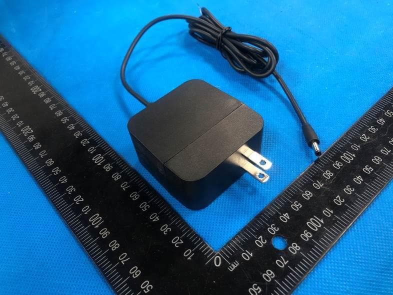
2AU7DFL048624
Mar 01, 2022POWER BANK
Equipment Class
DCD - Part 15 Low Power Transmitter Below 1705 kHz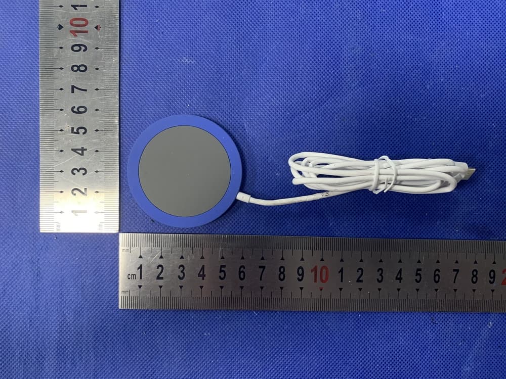
2AU7DWPC20076-01
May 02, 2021Wireless Charger
Equipment Class
DCD - Part 15 Low Power Transmitter Below 1705 kHz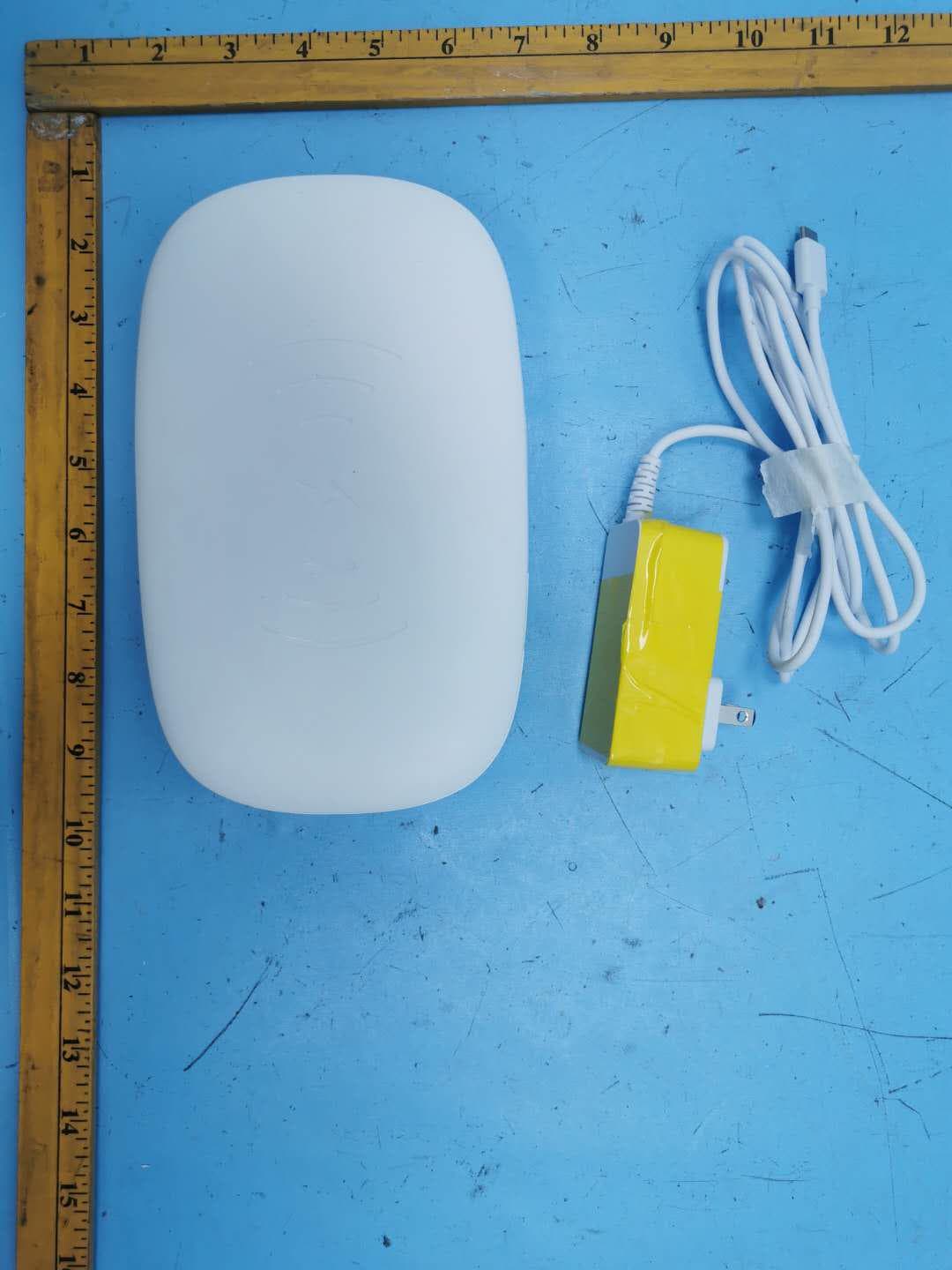
2AU7D-102407
Dec 29, 2020Phone Sanitizer with Qi Wireless Charger
Equipment Class
DCD - Part 15 Low Power Transmitter Below 1705 kHz2AU7D-WPC20001-01
Jul 20, 2020wireless charging pad
Equipment Class
DCD - Part 15 Low Power Transmitter Below 1705 kHz
2AU7DDUAL10WGGL
Mar 29, 2020Dual 10 Watt Two Coil Wireless Charger
Equipment Class
8CC - Part 18 Consumer Device