2AUCK-FV1003DVHF Wireless Microphone
Enping Fly Sound Equipment Co.,Ltd.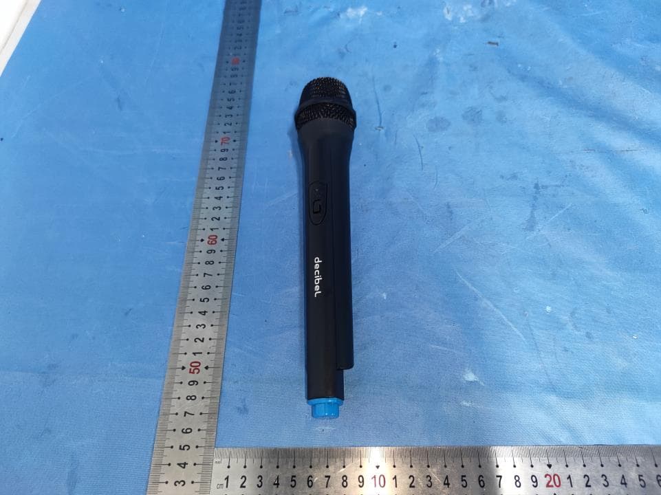
Click to zoom
Application Details
- Equipment Class
- DWM - Part 15 Wireless Microphone
- Date of Grant
- Jul 16, 2024
- Application Purpose
- Original Equipment
- Date of Application
- Jul 16, 2024
- Equipment Note
- VHF Wireless Microphone
- Frequency Range
- 214.20000000 - 214.20000000
- Country
- China
Documents & Files
Document Text
Text extracted from the exhibit documents filed with the FCC. Open a document above to read the original.
Users Manual
FV-1003 User manual Thanks for your support and trust to purchase our good quality wireless microphone. Please read this operation manual in detail in order to understand how to operate this product properly. Product Features: ▲ Using VHF 180-270 MHz frequency to avoid the interference. ▲ Using multilevel high frequency and middle frequency narrowband filter, so as to dispel any possible interference signals. ▲ With the low consumption components, the life of the battery will be much longer. ▲ With the power indication circuit in the handheld microphone, so you will know when to replace the battery. ▲ All use quartz crystal oscillating circuits, so the frequency is very steady. ▲ With the decreasing back-out whistle function, it can decrease the whistle efficiently. ▲ The tonality is quite good with the excellent crystal and components. Introduction of the Receiver: 1.ON/OFF Power Switch 2. 6. Volume Control Knob 3.AF LED indicator 4. Power LED indicator 5.RF LED indicator 7.8 Antenna 9. Power input 10. 1/4” (6.35mm) Audio input Introduction of the Transmitter: 1. Grill: To protect the capsule of the microphone. 2. Microphone Body 3. LED indicator 4. ON/OFF switch 5. Battery compartment: on back side of the microphone Operation of the receiver: 1. Connect the power adapter with the Power input ⑨. Then Plug the power adapter into a power socket. 2. Use the Audio Cable to connect the receiver 1/4” output ⑩ and 1/4” input of a mixer or active speaker. 3. Pull out antenna A & B ⑦ ⑧, make it vertically. 4. Turn ON the ON/OFF power switch ① and the power LED indicator ④ is lit. 5. When turn on the microphone, the receiver RF LED indicator ⑤ is lit. 6. The sound volume could be adjusted by the volume control knobs ② ⑥. 7. Please unplug the power adapter if you don't use for a long time. Operation of the transmitter: 1.Open the battery compartment cover ⑤ , install 2PCS AA batteries correctly, then cover it. 2.Turn ON the ON/OFF switch ④ when using,the LED indicator ③ is lit. 3.If the LED indicator ③ of the microphone is dark, please replace the batteries. 4.Please take out the batteries if you don't use transmitter for long time. Technical Specifications: Frequency Range: Modulation Mode:FM Pickup/Polar Pattern: Uni-Directional Impedance: 600 Ohms ± 30% Frequency Response: 60-13KHz Frequency Stability:±30ppm Dynamic Range: >80dB T.H.D:≤1% S/N Rate:>70dB Sensitivity: 30dB/uV Audio output: >25mV Output power: <10 mW Receiver Power Adapter: AC 90-240V,50Hz-60Hz, DC 12V Transmitter Power Supply: 2 x AA battery Wireless Range: up to 30m 214.2MHZ Problem Shooting: Problem Reason Solution 1. Power LED indicator light is not lit when turn on the receiver power switch. Receiver is without power supply. Connect the power adapter correctly. 2. No sound Wireless microphone do not turn “ON” Turn ON the power switch. Didn’t connect the Audio Cable. Connect the audio cable correctly. Didn’t turn on the volume. Turn on the volume control knob. Distance between wireless microphone and receiver is too far. Go close to the receiver. 3. Receiving distance is too short Antenna of receiver is not pulled out Pull out the antenna Low battery energy. Replace batteries. 4. Sound become worse. Low battery energy. Replace batteries. Other interference signal. Check if other equipment is causing interference. If it is not working normal after checking by yourself, Please contact seller or our agent. Please do not repair it by yourself. Caution: 1.Receiver should not be placed at dead corner in order to keep good signal condition. 2.Please don’t drop the microphone in order to avoid damage. 3.This system should be avoided direct sunlight/ liquid and do not close to a microwave. 4.Please don't disassemble by yourself because it may caused electric shock. What’s in the box: 1. Receiver: 1 PC 2. Transmitter: 2 PCS 3. Power Adapter: 1 PC 4. Audio Cable: 1 PC 5. AA battery: 4 PCS FCC Caution. This device complies with part 15 of the FCC Rules. Operation is subject to the following two conditions: (1) This device may not cause harmful interference, and (2) this device must accept any interference received, including interference that may cause undesired operation. Any Changes or modifications not expressly approved by the party responsible for compliance could void the user's authority to operate the equipment. Note: This equipment has been tested and found to comply with the limits for a Class B digital device, pursuant to part 15 of the FCC Rules. These limits are designed to provide reasonable protection against harmful interference in a residential installation. This equipment generates uses and can radiate radio frequency energy and, if not installed and used in accordance with the instructions, may cause harmful interference to radio communications. However, there is no guarantee that interference will not occur in a particular installation. If this equipment does cause harmful interference to radio or television reception, which can be determined by turning the equipment off and on, the user is encouraged to try to correct the interference by one or more of the following measures: -Reorient or relocate the receiving antenna. -Increase the separation between the equipment and receiver. -Connect the equipment into an outlet on a circuit different from that to which the receiver is connected. -Consult the dealer or an experienced radio/TV technician for help. * RF warning for Portable device: The device has been evaluated to meet general RF exposure requirement. The device can be used in portable exposure condition without restriction.
Cover Letter(s)
Enping Fly Sound Equipment Co.,Ltd. Add: Fourth Floor, 12th Building, No. 33, Enzhou Industrial Avenue, Enping City, Guangdong Province, China Date: 2024-7-8 FCC ID: 2AUCK-FV1003D Dear Sir/Madam, We, Enping Fly Sound Equipment Co.,Ltd. Hereby declares the following statement for Federal Communications Commission, PCB board, circuit, structure and internal of these model(s) are the same, Only model number is different for these model: Product name: VHF Wireless Microphone Model no.: FV-1003D, FV-1003, FV-308, FV-1058, FV-1001, FV-1007, FV-2017, FV-1211, PDWM91, FV-1003S Sincerely, Name/Title: BOEY TAN/manager Company: Enping Fly Sound Equipment Co.,Ltd. Address: Fourth Floor, 12th Building, No. 33, Enzhou Industrial Avenue, Enping City, Guangdong Province, China Phone: +86 13929092202 Fax: +86 13929092202 E-Mail: [email protected]
External Photos
Page 1 of 3 FCC ID: 2AUCK-FV1003D Guangdong Asia Hongke Test Technology Limited B1/F, Building 11, Junfeng Industrial Park, Chongqing Road, Heping Community, Fuhai Street, Bao'an District, Shenzhen, Guangdong, China. External Photos Photo 1 Photo 2 Page 2 of 3 FCC ID: 2AUCK-FV1003D Guangdong Asia Hongke Test Technology Limited B1/F, Building 11, Junfeng Industrial Park, Chongqing Road, Heping Community, Fuhai Street, Bao'an District, Shenzhen, Guangdong, China. Photo 3 Photo 4 Page 3 of 3 FCC ID: 2AUCK-FV1003D Guangdong Asia Hongke Test Technology Limited B1/F, Building 11, Junfeng Industrial Park, Chongqing Road, Heping Community, Fuhai Street, Bao'an District, Shenzhen, Guangdong, China. Photo 5 Photo 6 ------End------
ID Label/Location Info
Label Size: L20mm * W10mm 1. The label is silk-screen on the sample VHF Wireless Microphone Model Name: FV-1003D FCC ID: 2AUCK-FV1003D L W
Internal Photos
Page 1 of 3 FCC ID: 2AUCK-FV1003D Guangdong Asia Hongke Test Technology Limited B1/F, Building 11, Junfeng Industrial Park, Chongqing Road, Heping Community, Fuhai Street, Bao'an District, Shenzhen, Guangdong, China. Internal Photos Photo 1 Photo 2 Page 2 of 3 FCC ID: 2AUCK-FV1003D Guangdong Asia Hongke Test Technology Limited B1/F, Building 11, Junfeng Industrial Park, Chongqing Road, Heping Community, Fuhai Street, Bao'an District, Shenzhen, Guangdong, China. Photo 3 Photo 4 Antenna Page 3 of 3 FCC ID: 2AUCK-FV1003D Guangdong Asia Hongke Test Technology Limited B1/F, Building 11, Junfeng Industrial Park, Chongqing Road, Heping Community, Fuhai Street, Bao'an District, Shenzhen, Guangdong, China. Photo 5 Photo 6 ------End------
RF Exposure Info
RF Exposure evaluation FCC ID: 2AUCK-FV1003D Applicable Standard According to §1.1307(b)(1), systems operating under the provisions of this section shall be operated in a manner that ensures that the public is not exposed to radio frequency energy level in excess of the Commission’s guidelines. According to §1.1310 and §2.1093 RF exposure requirement KDB447498 v06: Mobile and Portable Devices RF Exposure Procedures and Equipment Authorization Policies 1.1. Requirement According to KDB447498 D01 General RF Exposure Guidance v06 Section 4.3.1 Standalone SAR test exclusion considerations: “Unless specifically required by the published RF exposure KDB procedures, standalone 1-g head or body and 10-g extremity SAR evaluation for general population exposure conditions, by measurement or numerical simulation, is not required when the corresponding SAR Test Exclusion Threshold condition, listed below, is satisfied. These test exclusion conditions are based on source-based time-averaged maximum conducted output power of the RF channel requiring evaluation, adjusted for tune-up tolerance, and the minimum test separation distance required for the exposure conditions.22 The minimum test separation distance is determined by the smallest distance from the antenna and radiating structures or outer surface of the device, according to the host form factor, exposure conditions and platform requirements, to any part of the body or extremity of a user or bystander (see 5) of section 4.1). To qualify for SAR test exclusion, the test separation distances applied must be fully explained and justified by the operating configurations and exposure conditions of the transmitter and applicable host platform requirements, typically in the SAR measurement or SAR analysis report, according to the required published RF exposure KDB procedures. When no other RF exposure testing or reporting is required, a statement of justification and compliance must be included in the equipment approval, in lieu of the SAR report, to qualify for the SAR test exclusion. When required, the device specific conditions described in the other published RF exposure KDB procedures must be satisfied before applying these SAR test exclusion provisions; for example, handheld PTT two-way radios, handsets, laptops & tablets etc.23 “ [(max. power of channel, including tune-up tolerance, mW)/ (min. test separation distance, mm)] · [√f (GHz)] ≤ 3.0 for 1-g SAR and ≤ 7.5 for 10-g extremity SAR, where: • f (GHz) is the RF channel transmit frequency in GHz • Power and distance are rounded to the nearest mW and mm before calculation • The result is rounded to one decimal place for comparison • 3.0 and 7.5 are referred to as the numeric thresholds in the step 2 below The test exclusions are applicable only when the minimum test separation distance is ≤ 50 mm and for transmission frequencies between 100 MHz and 6 GHz. When the minimum test separation distance is < 5 mm, a distance of 5 mm according to 5) in section 4.1 is applied to determine SAR test exclusion. Manufacturing Tolerance Wireless Microphone Frequency EIRP (MHz) 214.2 Target (dBm) 6 Tolerance ± (dB) 1 2. E v a l u a t i o n Res u l t Standalone Band/Mode f (GHz) Antenna Distance RF output power including tune up SAR Test Exclusion Threshold SAR Test Exclusion Estimated (mm) dBm mW SAR Wireless Microphone 0.2142 5 7 5.01 0.464<3.0 Yes / Remark: When the minimum test separation distance is < 5 mm, a distance of 5 mm according to f) in section 4.1 is applied to determine SAR test exclusion. 3. C o n c l u s i o n The measurement results comply with the FCC Limit per 47 CFR 2.1093 for the uncontrolled RF Exposure and SAR Exclusion Threshold per KDB 447498 v06, No SAR is required. .....................End.........................
Test Report
Page 1 of 23 Report No.: AIT24060410FW1 Guangdong Asia Hongke Test Technology Limited B1/F, Building 11, Junfeng Industrial Park, Chongqing Road, Heping Community, Fuhai Street, Bao'an District, Shenzhen, Guangdong, China. TEST REPORT Client Information: Applicant: Enping Fly Sound Equipment Co.,Ltd. Applicant add.: Fourth Floor, 12th Building, No. 33, Enzhou Industrial Avenue, Enping City, Guangdong Province, China Manufacturer: ENPING FLY SOUND EQUIPMENT CO.,LTD. Manufacturer add.: Fourth Floor, 12th Building, No. 33, Enzhou Industrial Avenue, Enping City, Guangdong Province, China Product Information: Product Name: VHF Wireless Microphone Model No.: FV-1003D Brand Name: Test samples.: AIT24060410001 FCC ID: 2AUCK-FV1003D Applicable standards: FCC Part 15.236 Prepared By: Guangdong Asia Hongke Test Technology Limited B1/F, Building 11, Junfeng Industrial Park, Chongqing Road, Heping Community, Fuhai Street, Bao'an District, Shenzhen, Guangdong, China Tel.: +86 0755-230967639 Fax.: +86 0755-230967639 Date of Receipt: June 07, 2024 Date of Test: June 07~ June 18, 2024 Date of Issue: June 18, 2024 Test Result: Pass This device described above has been tested by Guangdong Asia Hongke Test Technology Limited and the test results show that the equipment under test (EUT) is in compliance with the FCC requirements. And it is applicable only to the tested sample identified in the report. Note: This report shall not be reproduced except in full, without the written approval of Guangdong Asia Hongke Test Technology Limited, this document may be altered or revised by Guangdong Asia Hongke Test Technology Limited, personal only, and shall be noted in the revision of the document. This test report must not be used by the client to claim product endorsement. Reviewed by: Approved by: Leon.yi Sean She Page 2 of 23 Report No.: AIT24060410FW1 Guangdong Asia Hongke Test Technology Limited B1/F, Building 11, Junfeng Industrial Park, Chongqing Road, Heping Community, Fuhai Street, Bao'an District, Shenzhen, Guangdong, China. Table of Contents Page 1. SUMMARY OF TEST RESULTS 4 1.1 TEST FACTORY 5 1.2 DEVIATION FROM STANDARD 5 1.3 ABNORMALITIES FROM STANDARD CONDITIONS 5 1.4 TEST LOCATION 5 1.5 MEASUREMENT UNCERTAINTY 5 2. GENERAL INFORMATION 6 2.1 GENERAL DESCRIPTION OF THE EUT 6 2.2 DESCRIPTION OF THE TEST MODES 7 2.3 BLOCK DIAGRAM SHOWING THE CONFIGURATION OF SYSTEM TESTED 8 2.4 DESCRIPTION OF NECESSARY ACCESSORIES AND SUPPORT UNITS 8 2.5 TEST EQUIPMENT 9 3. EMC EMISSION TEST 10 3.1 CONDUCTED EMISSION MEASUREMENT 10 3.2 RADIATED EMISSIONS MEASUREMENT 12 4. PART 15.236 REQUIREMENTS 17 4.1 FREQUENCY STABILITY VS. TEMPERATURE & VOLTAGE 17 4.2 OCCUPIED BANDWIDTH 19 4.3 RADIATED POWER 21 PHOTOS OF TEST SETUP 23 Page 3 of 23 Report No.: AIT24060410FW1 Guangdong Asia Hongke Test Technology Limited B1/F, Building 11, Junfeng Industrial Park, Chongqing Road, Heping Community, Fuhai Street, Bao'an District, Shenzhen, Guangdong, China. Revision History Revision Issue Date Revisions Revised By 01 June 18, 2024 Initial Issue Sean She Page 4 of 23 Report No.: AIT24060410FW1 Guangdong Asia Hongke Test Technology Limited B1/F, Building 11, Junfeng Industrial Park, Chongqing Road, Heping Community, Fuhai Street, Bao'an District, Shenzhen, Guangdong, China. 1. SUMMARY OF TEST RESULTS Test procedures according to the technical standards: The EUT has been tested according to FCC CFR 47: Part 15.236: Operation of wireless microphones in the bands 54-72 MHz, 76-88 MHz, 174-216 MHz, 470-608 MHz and 614-698 MHz. Emission Standard Item Limit Result FCC 15.236(g) Radiated Spurious Emission Refer to 300 422-1 V1.4.2 (8.4) PASS FCC 15.236(d)(1) EIRP ≤50 mW PASS FCC 15.215 Occupied Bandwidth -- PASS FCC 15.236(f)(3) Frequency tolerance ±0.005% PASS FCC 15.236(g) Necessary Bandwidth (Mask) Refer to 300 422-1 V1.4.2 (8.3) PASS FCC 15.207 Conducted Emission -- N/A NOTE: (1) “N/A” denotes test is not applicable in this Test Report. Page 5 of 23 Report No.: AIT24060410FW1 Guangdong Asia Hongke Test Technology Limited B1/F, Building 11, Junfeng Industrial Park, Chongqing Road, Heping Community, Fuhai Street, Bao'an District, Shenzhen, Guangdong, China. 1.1 TEST FACTORY The test facility is recognized, certified or accredited by the following organizations: FCC-Registration No.: 251906 Designation Number: CN1376 Guangdong Asia Hongke Test Technology Limited has been registered and fully described in a report filed with the (FCC) Federal Communications Commission. The acceptance letter from the FCC is maintained in our files. IC —Registration No.: 31737 CAB identifier: CN0165 The 3m Semi-anechoic chamber of Guangdong Asia Hongke Test Technology Limited has been registered by Certification and Engineering Bureau of Industry Canada for radio equipment testing with Registration No.: 31737 A2LA-Lab Cert. No.: 7133.01 Guangdong Asia Hongke Test Technology Limited has been accredited by A2LA for technical competence in the field of electrical testing, and proved to be in compliance with ISO/IEC 17025: 2017 General Requirements for the Competence of Testing and Calibration Laboratories and any additional program requirements in the identified field of testing. 1.2 DEVIATION FROM STANDARD None 1.3 ABNORMALITIES FROM STANDARD CONDITIONS None 1.4 TEST LOCATION Guangdong Asia Hongke Test Technology Limited Address: B1/F, Building 11, Junfeng Industrial Park, Chongqing Road, Heping Community, Fuhai Street, Bao'an District, Shenzhen, Guangdong, China Tel.: +86 0755-230967639 Fax.: +86 0755-230967639 1.5 MEASUREMENT UNCERTAINTY Test Item Frequency Range Measurement Uncertainty Notes Radiated Emission 0.009MHz-30MHz 3.10dB (1) Radiated Emission 30MHz-1GHz 3.75dB (1) Radiated Emission 1GHz-18GHz 3.88dB (1) Radiated Emission 18GHz-40GHz 3.88dB (1) AC Power Line Conducted Emission 0.15MHz ~ 30MHz 1.20dB (1) Note (1): The measurement uncertainty is for coverage factor of k=2 and a level of confidence of 95%. Page 6 of 23 Report No.: AIT24060410FW1 Guangdong Asi…
Text truncated - open the document above for the full version.
Test Report
1 1
Test Setup Photos
Page 1 of 1 FCC ID: 2AUCK-FV1003D Guangdong Asia Hongke Test Technology Limited B1/F, Building 11, Junfeng Industrial Park, Chongqing Road, Heping Community, Fuhai Street, Bao'an District, Shenzhen, Guangdong, China. Test Setup Photo DWM Radiated Emission ------End------
Contact Information
Applicant
BOEY TAN(manager)
Test Firm
Guangdong Asia Hongke Test Technology LimitedDarren Ding
[email protected]185656258618
Technical Specifications
| # | Rule Parts | Frequency Range | Power Output | Tolerance |
|---|---|---|---|---|
| 1 | 15C | 214.2 MHz - 214.2 MHz | 4.30 mW | 0.0023700000 % |
Other Applications from Enping Fly Sound Equipment Co.,Ltd.
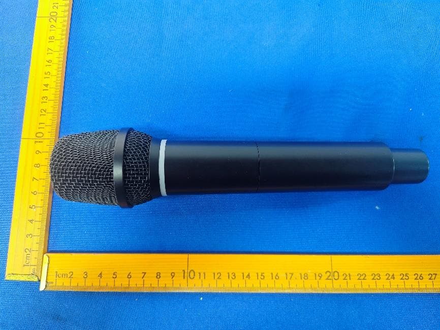
2AUCK-PDWM95
Jan 21, 2026UHF WIRELESS MICROPHONE
Equipment Class
DWM - Part 15 Wireless Microphone