2AUET-202018SRMMessenger
Badge Messenger, INC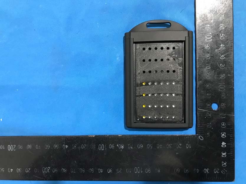
Click to zoom
Application Details
- Equipment Class
- DSS - Part 15 Spread Spectrum Transmitter
- Date of Grant
- Jun 08, 2020
- Application Purpose
- Original Equipment
- Date of Application
- Jun 08, 2020
- Equipment Note
- Messenger
- Frequency Range
- 902.30000000 - 914.90000000
- Company
- Badge Messenger, INC
- Country
- United States
Documents & Files
Document Text
Text extracted from the exhibit documents filed with the FCC. Open a document above to read the original.
Users Manual
The 4-stages of a request are: SENDING–Showing that your request is sent. RECEIVED–Confirms delivery of request. ASSIGNED–Request has been Assigned. RESOLVED? –Press the Yesbutton after the issue is resolved. After which the Messenger will return to home screen displaying the time. The C.A.R.E.L. operator may also Resolve the request should it occur else ware. Responding in Emergency Mode: A LOCKDOWNevent can be initiated from any Messenger badge holder by depressing the SECURITY and MEDICALsimultaneously for 3-seconds. This will produce two separate buzz events. After the second long buzz, release the buttons and a Lockdown will activate. In similar manner a FIRE CONFIRM notice can be sent from any Messenger badge holder when HELP and MAINTENANCEare pressed simultaneously for 3-seconds. This process is the same as the Lockdown. Emergency process: (step by step) •What you will SEEon the display •WhentoPUSHthebuttons •WhatyouwillFEELfromtheMessenger Step 1: LOCKDOWN* -Event -CHECK IN PresstheYESbuttonimmediately. TripleBuzz/Blink(5X) Step 2: Are You Safe? / Safe? CHECK-IN Press the YESbutton when you’re safe. Press the NObutton if you’re not safe. Single buzz/blink. “Event IN PROGRESS” This is the wait cycle until the event is called off. Step 3: ALL CLEAR / ALL CLEAR-CHECK IN PresstheYESbutton. TripleBuzz/Blink(5X) Step 4: RETURN / RETURN-CHECK IN Press the YESbutton once you’re back in place. Press the NObutton If you cannot comply. Single buzz/blink. Welcome! YourMessengerisalightweighttwo-way communicationBadgeholder designedfor assistancerequestsandcrisissupport.Any ButtonpressissenttotheC.A.R.E.L. requestingassistance,orreportingyour conditioninacrisissituation.TheMessenger willacceptuptotwostandardthickness badges,e.g.PhotoIdentificationandRFID buildingaccessbadgesofsimilarthickness. To Start: Charge your Messenger: Power down and insert USB charger connector into the Messenger. Charge until the amber LED is out. This will be 80% of full battery charge. Powering On your Messenger: Press and hold the NO button (5-6 sec.) until the buzz to power on. The system time will appear within several seconds if you are in range of the C.A.R.E.L. Powering Off your Messenger: Press and hold NO button (5-6 sec) until the second buzz to power off the Messenger. this is Recommended state for charging. Messenger Operation: CONNECTION:TheMessengerwilldisplay “Connected“whenconnectedwiththe C.A.R.E.L.“Offline”isdisplayedwhennosignal forconnectionisavailable. Name:Yournamewillappearatdisplaytop. Time:Timeisdisplayedinreadymode. ElapsedTimer:TheEventelapsedtimeris displayedindisplaylowerrightcorner Request:TherequestEventtype isdisplayed intheupperleftcorner Sub-menu:Thesub-menuchoicesforeach requestaredisplayedfor5-secondsatthe beginningofanyrequest. HowtouseRequestButtons: Pressinganyrequestbuttonfor1-secondwill produceaconfirmingbuzz.Thiswillstartsthe requestprocess.A 5-seconddelayisbuiltinto allowyoutoselectofone-of-fourcustom sub-menuchoices.Touchingthedarkgray touch-pointdotnexttoyourchoicewillselect. Ifnosub-menuoptionisselected,therequest willbeautomaticallysentafter5seconds. SRM quick start doc. 2.1 MESSENGER support.badgemessenger.com/start/srm Model: SRM Badge Messenger Limited Warranty -Summary: BadgeMessengerwarrantstoyouthatthisproduct isfreefromdefectsinmaterialsandworkmanship foraperiodofone(1)yearfromtheoriginaldate ofpurchasefromBadgeMessenger.See support .badgemessenger.comforproductspecific warrantyinformation,andtostartoractona warrantyclaim.ScanningtheQRcodeonyour Messengerwithyoursmartphonewillgiveyou instantdetailsregardingyourproductand coverage.BadgeMessenger’sentireliabilityand yourexclusiveremedyforanybreachofwarranty shallbe,atBadgeMessenger’soption,torepairor replaceafunctioningunitorrefundofthepurchase price,whenthehardwareisreturnedtothe manufacturer.Thesewarrantyprotectionsarein additiontoanylocalconsumerprotectionlaws. Yourwarrantyisvoidundertheseconditions: •PhysicalDamage. •WaterDamage. •Damagefromextremeheat. Forwarrantyclaim,sendtothisaddress: BadgeMessenger Attn:CustomerService(warrantyticketnumber) 11IndustrialBlvd SaukRapids,Minnesota56379 UseGuidelines:Safe&ProperUse ofYourMessenger Donotopenormodifytheproductnorshouldyou attempttoservicetheproducttoavoidriskof injuryduetobatterydamage.Donotimmerse productinanyliquidorexposetoanyheator moisture.Ifproductisexposedtooutofrange temperature,poweroffdeviceuntiltemperature rangehasstabilizedwithinthespecifiedoperating temperaturerange. Chargingtemperaturerange:32°Fto113°F Dischargetemperaturerange:-20°Fto140°F Nochargingpermittedbelowfreezing.Charging anddischargingatthehighendofthetemperature rangeresultsinashorterbatterylife. Thisproductisnotatoy andshouldnotbehandled bychildren. Ifproductisoperatingimproperly,pleasecontact BadgeMessengerCustomersupport. CompletelychargeyourMessengerpriortofirst use. PowerOffyourMessenger: PressandholdNOfor5-secondstopoweroff. PoweringOnyourMessenger: PressandholdNOfor5-secondstopoweron. ChargingyourMessenger: PoweroffandinsertUSBchargerconnectorinto theMessenger.Chargeuntiltheamberledgoes out. Important Safety, Compliance and Warranty Information Improperly,ormistreatedrechargeablebatteries maypresentariskofleak,chemicalburns,or explosionandpersonalinjury.DoNotopen, puncture,exposetoconductivematerials, moisture,liquid,orheatabove130°F(54°C).Do Notchargebatteryifitappearstobeleaking, discolored,deformed,orinanywayabnormal.Do Notleaveyourbatterydischargedorunusedfor prolongedperiodsoftime.DoNotshortcircuit. DoNotallowchildrentoplaywiththeMessenger, andbemindfulofanystrangulationhazard relatedtothelanyard,ifsoequipped.Batterylife varieswithusage.Non-operationalbatteries/units shouldbereturnedtoBadgeMessengerfor recycling.Warning:Altering,modifying,or changingtheMessengeroutsideofnormal operation maycreateahazardouscondition. Avoidshockhazardwhenrechargingbatteryby chargingawayfromanyliquidsource. English Read Manual before Product Use Warning! No User Serviceable Parts! Battery is n…
Text truncated - open the document above for the full version.
Cover Letter(s)
QA-FR-170-B Badge Messenger, INC. ADD: 11 Industrial Blvd, Sauk Rapids, Minnesota 56379 USA TEL: 320-281-2440 E-mail: [email protected] FCC Authorization Date: 2020-02-21 FEDERAL COMMUNICATIONS COMMISSION Authorization and Evaluation Division 7435 Oakland Mills Road Columbia, MD 21046 Subject: Agent Authorization To whom it may concern: We , Badge Messenger, INC., Hereby authorizes Bay Area Compliance Laboratories Corporation to act on its behalf in all matters relating to application for Equipment authorization, including the signing of all documents relating to these matters. All acts carried out by Bay Area Compliance Laboratory Corporation on our behalf shall have the same effect as o ur own action. We, the undersigned, hereby certify that we are not subject to a denial of federal benefits, that includes FCC benefits, pursuant to Section 5301 of the Anti-Drug Abuse Act of 1988, 21 U.S.C. 862. This authorization is valid until further written notice from the applicant. Sincerely Yours, Client’s signature Printed Name: Andrew Johannes Title: CFO
Cover Letter(s)
QA-FR-171-A Badge Messenger, INC. Add: 11 Industrial Blvd, Sauk Rap ids, Minnesota 56379 USA Tel: 320-281-2440 Email: [email protected] FCC Confidential Authorization Date:2020-02-21 FEDERAL COMMUNICATIONS COMMISSIONS Authorization and Evaluation Division 7435 Oakland Mills Road Columbia, MD 21046 Subject: Confidentiality Request regarding application for certification of FCC ID: In accordance with Sections 0.457 and 0.459 of the Commission’s Rules, Badge Messenger, INC hereby requests long-term confidential treatment of information accompanying this application as outlined below: Block Diagram Schematics Operation Description The above materials contain proprietary and confidential information not customarily released to the public. The public disclosure of these materials provides unjustified benefits to its competitors in the market. Sincerely, Signature: Andrew Johannes CFO 2AUET-202018SRM
External Photos
EXHIBIT B - EUT EXTERNAL PHOTOGRAPHS top bottom port
Internal Photos
EXHIBIT C - EUT INTERNAL PHOTOGRAPHS
RF Exposure Info
Note: This test report is prepared for the customer shown above and for the device described herein. It may not be duplicated or used in part without prior written consent from Bay Area Compliance Laboratories Corp. (Dongguan). This report must not be used by the customer to claim product certification, approval, or endorsement by A2LA* or any agency of the Federal Government. * This report may contain data that are not covered by the A2LA accreditation and are marked with an asterisk “*” SAR EVALUATION REPORT For Badge Messenger, INC 11 Industrial Blvd, Sauk Rapids, Minnesota 56379 USA FCC ID: 2AUET-202018SRM Report Type: Original Report Product Type: Messenger Report Number: RDG190813006-20 Report Date: 2020-02-21 Reviewed By: Rocky Xiao RF Engineer Prepared By: Bay Area Compliance Laboratories Corp. (Dongguan) No.69 Pulongcun, Puxinhu Industry Area, Tangxia, Dongguan, Guangdong, China Tel: +86-769-86858888 Fax: +86-769-86858891 www.baclcorp.com.cn Bay Area Compliance Laboratories Corp. (Dongguan) Report No.: RDG190813006-20 SAR Evaluation Report 2 of 35 Attestation of Test Results EUT Information EUT Description Messenger Tested Model SRM FCC ID 2AUET-202018SRM Serial Number RDG190813006-SA-S1 Test Date 2019-11-27 MODE Max. SAR Level(s) Reported(W/kg) Limit (W/kg) LoRa(10g Extremity SAR) 0.15 4.0 Applicable Standards FCC 47 CFR part 2.1093 Radiofrequency radiation exposure evaluation: portable devices IEEE1528:2013 IEEE Recommended Practice for Determining the Peak Spatial-Average Specific Absorption Rate (SAR) in the Human Head from Wireless Communications Devices: Measurement Techniques IEC 62209-2:2010 Human exposure to radio frequency fields from hand-held and body-mounted wireless communication devices-Human models, instrumentation, and procedures-Part 2: Procedure to determine the specific absorption rate (SAR) for wireless communication devices used in close proximity to the human body (frequency range of 30 MHz to 6 GHz) KDB procedures KDB 447498 D01 General RF Exposure Guidance v06 KDB 865664 D01 SAR Measurement 100 MHz to 6 GHz v01r04 KDB 865664 D02 RF Exposure Reporting v01r02 Note: This wireless device has been shown to be capable of compliance for localized specific absorption rate (SAR) for General Population/Uncontrolled Exposure limits specified in FCC 47 CFR part 2.1093 and has been tested in accordance with the measurement procedures specified in IEEE 1528-2013 and RF exposure KDB procedures. The results and statements contained in this report pertain only to the device(s) evaluated. Bay Area Compliance Laboratories Corp. (Dongguan) Report No.: RDG190813006-20 SAR Evaluation Report 3 of 35 TABLE OF CONTENTS DOCUMENT REVISION HISTORY ......................................................................................................................... 4 EUT DESCRIPTION .................................................................................................................................................... 5 TECHNICAL SPECIFICATION ......................................................................................................................................... 5 REFERENCE, STANDARDS, AND GUIDELINES .................................................................................................. 6 SAR LIMITS ................................................................................................................................................................. 7 FACILITIES .................................................................................................................................................................. 8 DESCRIPTION OF TEST SYSTEM .......................................................................................................................... 9 EQUIPMENT LIST AND CALIBRATION ............................................................................................................. 15 EQUIPMENTS LIST & CALIBRATION INFORMATION .................................................................................................... 15 SAR MEASUREMENT SYSTEM VERIFICATION .............................................................................................. 16 LIQUID VERIFICATION ............................................................................................................................................... 16 SYSTEM ACCURACY VERIFICATION ........................................................................................................................... 17 SAR SYSTEM VALIDATION DATA ..................................................................................................................... 18 EUT TEST STRATEGY AND METHODOLOGY ................................................................................................. 19 TEST POSITIONS FOR DEVICE OPERATING NEXT TO A PERSON’S EAR........................................................................ 19 CHEEK/TOUCH POSITION ........................................................................................................................................... 20 EAR/TILT POSITION ................................................................................................................................................... 20 TEST POSITIONS FOR BODY-WORN AND OTHER CONFIGURATIONS .............................................................................. 21 TEST DISTANCE FOR SAR EVALUATION .................................................................................................................... 21 SAR EVALUATION PROCEDURE ................................................................................................................................. 22 CONDUCTED OUTPUT POWER MEASUREMENT ........................................................................................... 23 PROVISION APPLICABLE ...........................................................................................................…
Text truncated - open the document above for the full version.
RF Exposure Info
APPENDIX C PROBE CALIBRATION CERTIFICATES DIPOLE CALIBRATION CERTIFICATES
RF Exposure Info
Report No.: RDG190813006-20 Page 1 of 6 Test Plot 1#:LoRa_ BackSide _Middle Channel DUT: Messenger; Type: SRM; Serial: RDG190813006-SA-S1 Communication System: LoRa_900MHz; Frequency: 908.5 MHz;Duty Cycle: 1:10.6 Medium parameters used: f = 908.5 MHz; σ = 0.902 S/m; ε r = 41.02; ρ = 1000 kg/m 3 Phantom section: Flat Section DASY5 Configuration: Probe: EX3DV4 - SN7329; ConvF(9.68, 9.68, 9.68) @ 908.5 MHz; Calibrated: 2019/10/22 Sensor-Surface: 1.4mm (Mechanical Surface Detection) Electronics: DAE4 Sn772; Calibrated: 2019/10/6 Phantom: SAM 1; Type: QD000P40CC; Serial: TP:1412 Measurement SW: DASY52, Version 52.10 (2); SEMCAD X Version 14.6.12 (7470) Area Scan (61x91x1): Interpolated grid: dx=1.500 mm, dy=1.500 mm Maximum value of SAR (interpolated) = 0.269 W/kg Zoom Scan (5x6x7)/Cube 0: Measurement grid: dx=8mm, dy=8mm, dz=5mm Reference Value = 11.56 V/m; Power Drift = 0.19 dB Peak SAR (extrapolated) = 0.440 W/kg SAR(1 g) = 0.239 W/kg; SAR(10 g) = 0.132 W/kg Maximum value of SAR (measured) = 0.255 W/kg 0 dB = 0.255 W/kg = -5.93 dBW/kg Report No.: RDG190813006-20 Page 2 of 6 Test Plot 2#:LoRa_ FrontSide _Low Channel DUT: Messenger; Type: SRM; Serial: RDG190813006-SA-S1 Communication System: LoRa_900MHz; Frequency: 902.3 MHz;Duty Cycle: 1:10.6 Medium parameters used: f = 902.3 MHz; σ = 0.889 S/m; ε r = 41.247; ρ = 1000 kg/m 3 Phantom section: Flat Section DASY5 Configuration: Probe: EX3DV4 - SN7329; ConvF(9.68, 9.68, 9.68) @ 902.3 MHz; Calibrated: 2019/10/22 Sensor-Surface: 1.4mm (Mechanical Surface Detection) Electronics: DAE4 Sn772; Calibrated: 2019/10/6 Phantom: SAM 1; Type: QD000P40CC; Serial: TP:1412 Measurement SW: DASY52, Version 52.10 (2); SEMCAD X Version 14.6.12 (7470) Area Scan (61x91x1): Interpolated grid: dx=1.500 mm, dy=1.500 mm Maximum value of SAR (interpolated) = 0.358 W/kg Zoom Scan (5x5x7)/Cube 0: Measurement grid: dx=8mm, dy=8mm, dz=5mm Reference Value = 6.681 V/m; Power Drift = 0.14 dB Peak SAR (extrapolated) = 0.825 W/kg SAR(1 g) = 0.296 W/kg; SAR(10 g) = 0.145 W/kg Maximum value of SAR (measured) = 0.345 W/kg 0 dB = 0.345 W/kg = -4.62 dBW/kg Report No.: RDG190813006-20 Page 3 of 6 Test Plot 3#:LoRa_ FrontSide _Middle Channel DUT: Messenger; Type: SRM; Serial: RDG190813006-SA-S1 Communication System: LoRa_900MHz; Frequency: 908.5 MHz;Duty Cycle: 1:10.6 Medium parameters used: f = 908.5 MHz; σ = 0.902 S/m; ε r = 41.02; ρ = 1000 kg/m 3 Phantom section: Flat Section DASY5 Configuration: Probe: EX3DV4 - SN7329; ConvF(9.68, 9.68, 9.68) @ 908.5 MHz; Calibrated: 2019/10/22 Sensor-Surface: 1.4mm (Mechanical Surface Detection) Electronics: DAE4 Sn772; Calibrated: 2019/10/6 Phantom: SAM 1; Type: QD000P40CC; Serial: TP:1412 Measurement SW: DASY52, Version 52.10 (2); SEMCAD X Version 14.6.12 (7470) Area Scan (61x91x1): Interpolated grid: dx=1.500 mm, dy=1.500 mm Maximum value of SAR (interpolated) = 0.323 W/kg Zoom Scan (6x6x7)/Cube 0: Measurement grid: dx=8mm, dy=8mm, dz=5mm Reference Value = 5.991 V/m; Power Drift = 0.19 dB Peak SAR (extrapolated) = 0.803 W/kg SAR(1 g) = 0.291 W/kg; SAR(10 g) = 0.143 W/kg Maximum value of SAR (measured) = 0.322 W/kg 0 dB = 0.322 W/kg = -4.92 dBW/kg Report No.: RDG190813006-20 Page 4 of 6 Test Plot 4#:LoRa_ FrontSide _High Channel DUT: Messenger; Type: SRM; Serial: RDG190813006-SA-S1 Communication System: LoRa_900MHz; Frequency: 914.9 MHz;Duty Cycle: 1:10.6 Medium parameters used: f = 914.9 MHz; σ = 0.919 S/m; ε r = 41.043; ρ = 1000 kg/m 3 Phantom section: Flat Section DASY5 Configuration: Probe: EX3DV4 - SN7329; ConvF(9.68, 9.68, 9.68) @ 914.9 MHz; Calibrated: 2019/10/22 Sensor-Surface: 1.4mm (Mechanical Surface Detection) Electronics: DAE4 Sn772; Calibrated: 2019/10/6 Phantom: SAM 1; Type: QD000P40CC; Serial: TP:1412 Measurement SW: DASY52, Version 52.10 (2); SEMCAD X Version 14.6.12 (7470) Area Scan (61x91x1): Interpolated grid: dx=1.500 mm, dy=1.500 mm Maximum value of SAR (interpolated) = 0.324 W/kg Zoom Scan (5x5x7)/Cube 0: Measurement grid: dx=8mm, dy=8mm, dz=5mm Reference Value = 5.891 V/m; Power Drift = 0.10 dB Peak SAR (extrapolated) = 0.809 W/kg SAR(1 g) = 0.283 W/kg; SAR(10 g) = 0.137 W/kg Maximum value of SAR (measured) = 0.328 W/kg 0 dB = 0.328 W/kg = -4.84 dBW/kg Report No.: RDG190813006-20 Page 5 of 6 Test Plot 5#:LoRa_ RightSide _Middle Channel DUT: Messenger; Type: SRM; Serial: RDG190813006-SA-S1 Communication System: LoRa_900MHz; Frequency: 908.5 MHz;Duty Cycle: 1:10.6 Medium parameters used: f = 908.5 MHz; σ = 0.902 S/m; ε r = 41.02; ρ = 1000 kg/m 3 Phantom section: Flat Section DASY5 Configuration: Probe: EX3DV4 - SN7329; ConvF(9.68, 9.68, 9.68) @ 908.5 MHz; Calibrated: 2019/10/22 Sensor-Surface: 1.4mm (Mechanical Surface Detection) Electronics: DAE4 Sn772; Calibrated: 2019/10/6 Phantom: SAM 1; Type: QD000P40CC; Serial: TP:1412 Measurement SW: DASY52, Version 52.10 (2); SEMCAD X Version 14.6.12 (7470) Area Scan (41x91x1): Interpolated grid: dx=1.500 mm, dy=1.500 mm Maximum value of SAR (interpolated) = 0.186 W/kg Zoom Scan (5x5x7)/Cube 0: Measurement grid: dx=8mm, dy=8mm, dz=5mm Reference Value = 13.56 V/m; Power Drift = 0.05 dB Peak SAR (extrapolated) = 0.304 W/kg SAR(1 g) = 0.156 W/kg; SAR(10 g) = 0.083 W/kg Maximum value of SAR (measured) = 0.184 W/kg 0 dB = 0.184 W/kg = -7.35 dBW/kg Report No.: RDG190813006-20 Page 6 of 6 Test Plot 6#:LoRa_ BottomSide _Middle Channel DUT: Messenger; Type: SRM; Serial: RDG190813006-SA-S1 Communication System: LoRa_900MHz; Frequency: 908.5 MHz;Duty Cycle: 1:10.6 Medium parameters used: f = 908.5 MHz; σ = 0.902 S/m; ε r = 41.02; ρ = 1000 kg/m 3 Phantom section: Flat Section DASY5 Configuration: Probe: EX3DV4 - SN7329; ConvF(9.68, 9.68, 9.68) @ 908.5 MHz; Calibrated: 2019/10/22 Sensor-Surface: 1.4mm (Mechanical Surface Detection) Electronics: DAE4 Sn772; Calibrated: 2019/10/6 Phantom: SAM 1; Type: QD000P40CC; Serial: TP:1412 Measurement SW: DASY52, Version 52.10 (2); SEMCAD X Version 14.6.12 (7470) Area Scan (41x71x1): Interpolated gr…
Text truncated - open the document above for the full version.
RF Exposure Info
Report No.: RDG190813006-20 Page 1 of 3 APPENDIX B EUT TEST POSITION PHOTOS Liquid depth ≥ 15cm Phantom Type: Twin SAM; Model:Twin SAM V5.0; S/N: 1412 Report No.: RDG190813006-20 Page 2 of 3 Back Side Setup Photo(0mm) FrontSide Setup Photo(0mm) Report No.: RDG190813006-20 Page 3 of 3 RightSide Setup Photo(0mm) BottomSide Setup Photo(0mm)
Test Report
FCC PART 15.247 TEST REPORT For Badge Messenger, INC 11 Industrial Blvd, Sauk Rapids, Minnesota 56379 USA FCC ID:2AUET-202018SRM Report Type: Original Report Product Name: Messenger Report Number: RDG190813006-00B Re port Date: 2020-02-11 Reviewed By: Ivan Cao Assistant manager Test Laboratory: Bay Area Compliance Laboratories Corp. (Dongguan) No.69 Pulongcun, Puxinhu Industry Area, Tangxia, Dongguan, Guangdong, China Tel: +86-769-86858888 Fax: +86-769-86858891 www.baclcorp.com.cn Bay Area Compliance Laboratories Corp. (Dongguan) Report No.: RDG190813006-00B Page 2 of 43 TABLE OF CONTENTS GENERAL INFORMATION ....................................................................................................................................... 4 PRODUCT DESCRIPTION FOR EQUIPMENT UNDER TEST (EUT) ..................................................................................... 4 OBJECTIVE ................................................................................................................................................................... 4 RELATED SUBMITTAL(S)/GRANT(S) ............................................................................................................................. 4 TEST METHODOLOGY .................................................................................................................................................. 4 MEASUREMENT UNCERTAINTY .................................................................................................................................... 5 TEST FACILITY ............................................................................................................................................................. 5 DECLARATIONS ............................................................................................................................................................ 5 SYSTEM TEST CONFIGURATION .......................................................................................................................... 6 DESCRIPTION OF TEST CONFIGURATION ...................................................................................................................... 6 EUT EXERCISE SOFTWARE .......................................................................................................................................... 6 EQUIPMENT MODIFICATIONS ....................................................................................................................................... 6 SUPPORT EQUIPMENT LIST AND DETAILS .................................................................................................................... 6 SUPPORT CABLE LIST AND DETAILS ............................................................................................................................ 6 BLOCK DIAGRAM OF TEST SETUP ................................................................................................................................ 7 SUMMARY OF TEST RESULTS ............................................................................................................................... 8 FCC §15.247 (i) & §1.1310 & §2.1093- RF Exposure ................................................................................................. 9 APPLICABLE STANDARD .............................................................................................................................................. 9 FCC §15.203- ANTENNA REQUIREMENT ............................................................................................................ 10 APPLICABLE STANDARD ............................................................................................................................................ 10 ANTENNA CONNECTOR CONSTRUCTION .................................................................................................................... 10 FCC §15.207 (a) – AC LINE CONDUCTED EMISSIONS ..................................................................................... 11 APPLICABLE STANDARD ............................................................................................................................................ 11 EUT SETUP ................................................................................................................................................................ 11 EMI TEST RECEIVER SETUP ....................................................................................................................................... 11 TEST PROCEDURE ...................................................................................................................................................... 11 CORRECTED AMPLITUDE & MARGIN CALCULATION ................................................................................................. 12 TEST EQUIPMENT LIST AND DETAILS ......................................................................................................................... 12 TEST DATA ................................................................................................................................................................ 12 FCC §15.209, §15.205 & §15.247(d) - SPURIOUS EMISSIONS ............................................................................. 15 APPLICABLE STANDARD ............................................................................................................................................ 15 EUT SETUP ................................................................................................................................................................ 15 EMI TEST RECEIVER & SPECTRUM ANALYZER SETUP .............................................................................................. 16 TEST PROCEDURE ...................................................................................................................................................... 16 TEST EQUI…
Text truncated - open the document above for the full version.
Test Setup Photos
EXHIBIT D - TEST SETUP PHOTOGRAPHS Conducted Emissions Front View Conducted Emissions Side View Radiated Emission Below 1GHz View Radiated Emission Above 1GHz View
Contact Information
Applicant
Andrew Johannes(CFO)
Test Firm
Bay Area Compliance Laboratories Corp.(Dongguan)David Zhang
[email protected]0086 0769 86858888
Technical Specifications
| # | Rule Parts | Frequency Range | Power Output |
|---|---|---|---|
| 1 | 15C | 902.3 MHz - 914.9 MHz | 54.00 mW |
Other Applications from Badge Messenger, INC
2AUET-202018SRX
Jun 08, 2020CAREL
Equipment Class
DXX - Part 15 Low Power Communication Device Transmitter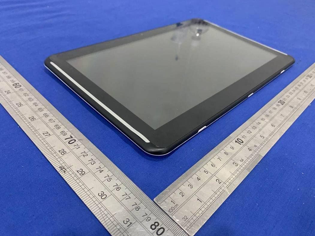
2AUET-191813SRM
May 14, 2020Tablet computer
Equipment Class
DSS - Part 15 Spread Spectrum Transmitter