2AUET-202018SRXCAREL
Badge Messenger, INC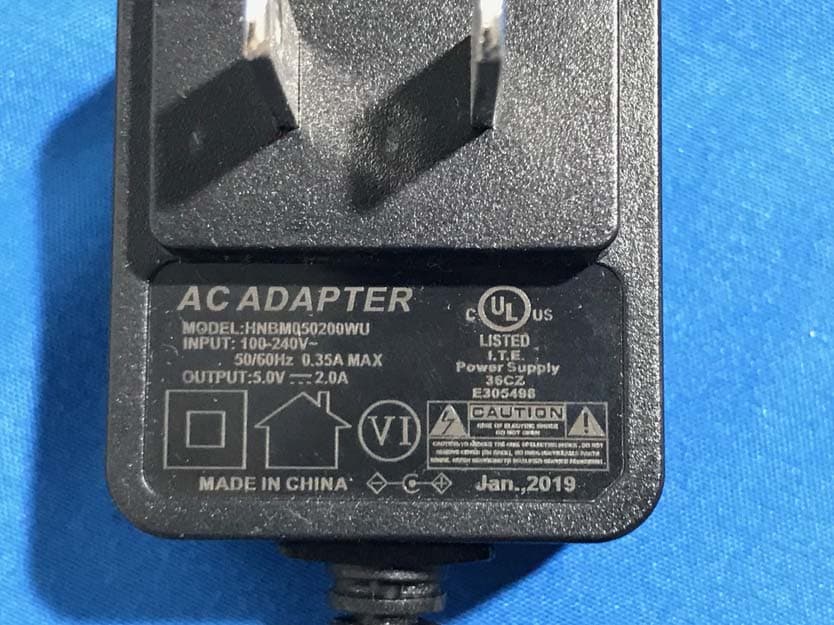
Click to zoom
Application Details
- Equipment Class
- DXX - Part 15 Low Power Communication Device Transmitter
- Date of Grant
- Jun 08, 2020
- Application Purpose
- Original Equipment
- Date of Application
- Jun 08, 2020
- Equipment Note
- CAREL
- Frequency Range
- 923.50000000 - 927.70000000
- Company
- Badge Messenger, INC
- Country
- United States
Documents & Files
Document Text
Text extracted from the exhibit documents filed with the FCC. Open a document above to read the original.
Users Manual
C.A.R.E.L. Command Center Model SRX The Badge Messenger System: Warnings and Notices. TheBadgeMessengersystemisdesignedtosupportyourcurrentCrisis ManagementandSafetyprotocol.Assuch,iftheuseofpublicaddress systemsiscurrentlypartofyourCrisisprotocol,youshouldcontinueto useitinconjunctionwiththeBadgeMessengersystem.EachMessenger hasbothahapticfeedback(vibratormotor),andahigh-brightnessLEDas sensoryalerts.Thesehoweverarenotalwaysenoughandtherelianceon thesealonefornotificationshouldnotbepartoftheemergencyprotocol. TheMessengerisdesignedtotransmitandreceivewithaminimumof auditorydisruptionforthenormalclassroomyetbeeasilyfeltandheard withrepeatedhapticstimulation.Withusage,theassociatedprotocolcan beadaptedtotakeadvantageoftheoperationoftheMessenger. FCC Compliance Statement This device complies with part 15 of the FCC Rules. Operation is subject to the following two conditions: (1) this device may not cause harmful interference, and (2) this device must accept any interference received, including interference that may cause undesired operation. CAUTION: The grantee is not responsible for any changes or modifications not expressly approved by the party responsible for compliance. Such modifications could void the user’s authority to operate the equipment. NOTE: This equipment has been tested and found to comply with the limits for a Class B digital device, pursuant to part 15 of the FCC Rules. These limits are designed to provide reasonable protection against harmful interference in a residential installation. This equipment generates, uses, and can radiate radio frequency energy, and if not installed and used in accordance with the instructions, may cause harmful interference to radio communications. However, there is no guarantee that interference will not occur in a particular installation. If this equipment does cause harmful interference to radio or television reception, which can be determined by turning the equipment off and on, the user is encouraged to try to correct the interference by one or more of the following measures: –Reorient or relocate the receiving antenna. –Increase the separation between the equipment and receiver. –Connect the equipment into an outlet on a circuit different from that to which the receiver is connected. –Consult the dealer or an experienced radio/TV technician for help. This equipment complies with the FCC radiation exposure limits set forth for an uncontrolled environment. This transmitter must not be co-located or operating in conjunction with any other antenna or transmitter. Warranty TheCARELiscoveredfordefectsinworkmanshiporpartsfailureforaperiodof12-monthsfrom dateofpurchase.BadgeMessengerwillatitssolediscretion,replaceorrepairanydefective devicecoveredwithinthewarrantyperiod.Warrantywillnotcoverdamageduetomisuse,abuse, waterdamage,tamper,ordisassembly.Theuseofunauthorizedaccessoriesmayalsovoidyour warranty.Pleaseseetheprecautions(1.2)andthesafetyinstructions(1.3)forfurtherinformation regardingthesafeoperationoftheCAREL. 1.0 Introduction 1.1 Acknowledgement 1.2 Precautions 1.3 Safety Instructions 1.4 Abbreviations / Terms 3.0 Setup 3.1 Hardware 3.2 Power 3.3 CAREL Setup / Gateway 3.4 Screen nomenclature 6.0 Emergency Events 6.1 CAREL initiated events 6.2 Reporting 7.0 Roll Call 7.1 Automatic Roll Call 7.2 Push Roll Call 8.0 Administration options 8.1 New Messenger Management 8.2 Messenger management 8.3 User management 8.4 Request sub-menu options 8.5 Notice option management 8.6 User category management 8.7 Reports 8.8 General Settings 8.9 Master Config. File 8.10 System Backup 2.0 Introduction to CAREL 2.1 Contents included 2.2 External Case Features 4.0 Operation 4.1 Downloading a MCF to the CAREL 4.2 Uploading a MCF to the Portal 4.3 Adding Messengers 4.4 Assigning Messengers 4.5 Adding Repeaters to the system Table of Contents Introduction 1.1 Acknowledgement Thank you for choosing Badge Messenger as a tool for improving your communication protocol. The CAREL is an integral part of the system and should give years of pleasant service. Please review the safety and precautionary portions of this manual to ensure a long and useful life. Please see the statement on the back cover regarding the proper integration of Badge Messenger into your school’s protocol. 1.2 Precautions •Please keep this equipment dry and avoid placing CAREL near heat sources. •Place the CAREL on a level surface and protect from accidental tipping. •Do not subject the unit to strong impacts or vibration. •When stationary, always keep the CAREL plugged in . for remote usage, reconnect once finished by replacing charger cable thru the kickstand and fully inserting it into the power port. •Do not place the charger cable under the kickstand as this creates an unstable effect on the unit. •Do not use metal objects on the display screen. •Use the supplied cleaning cloth to clean the screen. Apply light pressure to avoid scratching. Alcohol or solvent based products will damage the surface of the unit and could remove the printed text. •ALWAYS use the wrist lanyard when operating portably, this reduces the risk of dropping the unit and damaging it. 1.3 Safety Instructions •The CAREL is a tablet-based device that has separate radios (LoRa) for the transmission/reception of data. Please provide a metal free pathway to the gateway for best results.. It is advised to place this device over 8” away from other objects, people, or equipment for best performance. 1.4 Abbreviations / Terms •C.A.R.E.L = Communicate –Alert –Respond –Evaluate –Learn •MCF = Master Configuration File 5.0 Requests 5.1 Managing incoming requests 5.2 Forwarding Requests 5.3 Sending outgoing Notices 9.0 Advanced Settings 9.1 Managing incoming requests 9.2 Forwarding Requests 9.3 Sending outgoing Notices 2.1 Contents included 1.CAREL Display Unit. 2.Power Adaptor. 3.USB Transfer Drive (transferring files to/from the CAREL). 4.Transfer Drive extension Cable. 5.USB-A to USB-Micro Cable (for programming Messengers). 6.US…
Text truncated - open the document above for the full version.
Cover Letter(s)
INC INC QA-FR-170-B Badge Messenger, ADD: 11 Industrial Blvd, Sauk Rapids, Minnesota 56379 USA TEL: 320-281-2440 E-mail: [email protected] FCC Authorization Date: 2020-02-21 FEDERAL COMMUNICATIONS COMMISSION Authorization and Evaluation Division 7435 Oakland Mills Road Columbia, MD 21046 Subject: Agent Authorization To whom it may concern: We , Badge Messenger, , Hereby authorizes Bay Area Compliance Laboratories Corporation to act on its behalf in all matters relating to application for Equipment authorization, including the signing of all documents relating to these matters. All acts carried out by Bay Area Compliance Laboratory Corporation on our behalf shall have the same effect as o ur own action. We, the undersigned, hereby certify that we are not subject to a denial of federal benefits, that includes FCC benefits, pursuant to Section 5301 of the Anti-Drug Abuse Act of 1988, 21 U.S.C. 862. This authorization is valid until further written notice from the applicant. Sincerely Yours, Client’s signature Printed Name: Andrew Johannes Title: CFO
Cover Letter(s)
2AUET-202018SRX QA-FR-171-A Badge Messenger, INC Add: 11 Industrial Blvd, Sauk Rapids, Minnesota 56 379 USA Tel: 320-281-2440 E mail: [email protected] FCC Confidential Authorization Date:2020-02-21 FEDERAL COMMUNICATIONS COMMISSIONS Authorization and Evaluation Division 7435 Oakland Mills Road Columbia, MD 21046 Subject: Confidentiality Req uest regarding application for certification of FCC ID: In accordance with Sections 0.457 and 0.459 of the Commission’s Rules, Badge Messenger, INC hereby requests long-term confidential treatment of information accompanying this application as outlined below: Block Diagram Schematics Operation Description The above materials contain proprietary and confidential information not customarily released to the public. The public disclosure of these materials provides unjustified benefits to its competitors in the market. Sincerely, Signature: Andrew Johannes CFO
External Photos
EXHIBIT B - EUT EXTERNAL PHOTOGRAPHS
Internal Photos
EXHIBIT C - EUT INTERNAL PHOTOGRAPHS
Test Report
FCC PART 15.249 TEST REPORT For Badge Messenger, INC 11 Industrial Blvd, Sauk Rapids, Minnesota 56379 USA FCC ID:2AUET-202018SRX Report Type: Original Report Product Type: CAREL Re port Number: RDG190903003-00A Re port Date: 2020-05-25 Reviewed By: Ivan Cao Assistant manager Test Laboratory: Bay Area Compliance Laboratories Corp. (Dongguan) No.69 Pulongcun, Puxinhu Industry Area, Tangxia, Dongguan, Guangdong, China Tel: +86-769-86858888 Fax: +86-769-86858891 www.baclcorp.com.cn Bay Area Compliance Laboratories Corp. (Dongguan) Report No.: RDG190903003-00A Page 2 of 23 TABLE OF CONTENTS GENERAL INFORMATION ....................................................................................................................................... 3 PRODUCT DESCRIPTION FOR EQUIPMENT UNDER TEST (EUT) ..................................................................................... 3 OBJECTIVE ................................................................................................................................................................... 3 RELATED SUBMITTAL(S)/GRANT(S) ............................................................................................................................. 3 TEST METHODOLOGY .................................................................................................................................................. 3 MEASUREMENT UNCERTAINTY .................................................................................................................................... 4 TEST FACILITY ............................................................................................................................................................. 4 DECLARATIONS ............................................................................................................................................................ 4 SYSTEM TEST CONFIGURATION .......................................................................................................................... 5 JUSTIFICATION ............................................................................................................................................................. 5 EUT EXERCISE SOFTWARE .......................................................................................................................................... 5 EQUIPMENT MODIFICATIONS ....................................................................................................................................... 5 LOCAL SUPPORT EQUIPMENT LIST AND DETAILS ........................................................................................................ 5 SUPPORT CABLE LIST AND DETAILS ............................................................................................................................ 5 BLOCK DIAGRAM OF TEST SETUP ................................................................................................................................ 6 SUMMARY OF TEST RESULTS ............................................................................................................................... 7 FCC§15.203 - ANTENNA REQUIREMENT .............................................................................................................. 8 APPLICABLE STANDARD .............................................................................................................................................. 8 ANTENNA CONNECTOR CONSTRUCTION ...................................................................................................................... 8 FCC §15.207 (A)– AC LINE CONDUCTED EMISSIONS ....................................................................................... 9 APPLICABLE STANDARD .............................................................................................................................................. 9 EUT SETUP .................................................................................................................................................................. 9 EMI TEST RECEIVER SETUP ......................................................................................................................................... 9 TEST PROCEDURE ...................................................................................................................................................... 10 CORRECTED AMPLITUDE & MARGIN CALCULATION ................................................................................................. 10 TEST EQUIPMENT LIST AND DETAILS ......................................................................................................................... 10 TEST DATA ................................................................................................................................................................ 11 FCC§15.205, §15.209&§15.249- RADIATED EMISSIONS .................................................................................... 13 APPLICABLE STANDARD ............................................................................................................................................ 13 EUT SETUP ................................................................................................................................................................ 13 TEST EQUIPMENT SETUP ............................................................................................................................................ 14 TEST PROCEDURE ...................................................................................................................................................... 15 CORRECTED AMPLITUDE & MARGIN CALCULATION ................................................................................................. 15 TEST EQUIPMENT LIST AND DETAILS ..............................................................................................................…
Text truncated - open the document above for the full version.
Test Setup Photos
EXHIBIT D - TEST SETUP PHOTOGRAPHS Conducted Emissions Front View Conducted Emissions Side View Radiated Emission Below 1GHz View Radiated Emission Above 1GHz View
Contact Information
Applicant
Andrew Johannes(CFO)
Test Firm
Bay Area Compliance Laboratories Corp.(Dongguan)David Zhang
[email protected]0086 0769 86858888
Technical Specifications
| # | Rule Parts | Frequency Range | Power Output |
|---|---|---|---|
| 1 | 15C | 923.5 MHz - 927.7 MHz | - |
Other Applications from Badge Messenger, INC
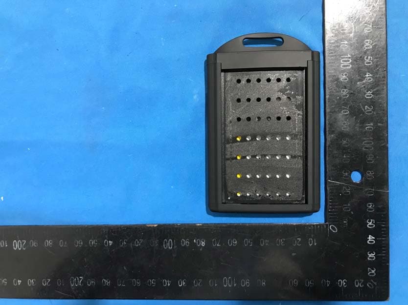
2AUET-202018SRM
Jun 08, 2020Messenger
Equipment Class
DSS - Part 15 Spread Spectrum Transmitter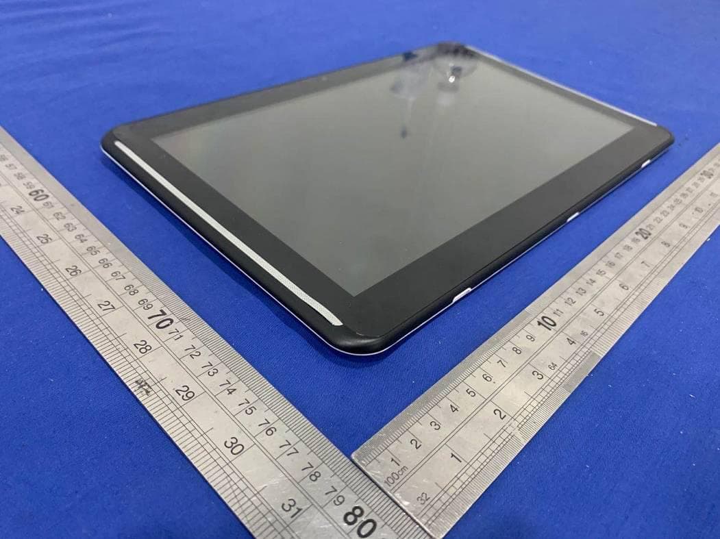
2AUET-191813SRM
May 14, 2020Tablet computer
Equipment Class
DSS - Part 15 Spread Spectrum Transmitter