2AUEW-ZK306Bluetooth Speaker
Shenzhen Yikexin Network Technology Co.,Ltd.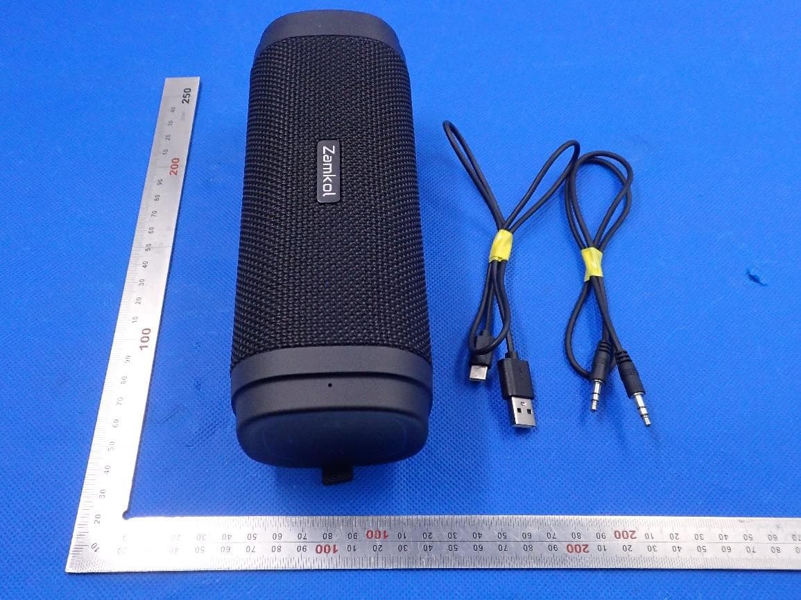
Click to zoom
Application Details
- Equipment Class
- DSS - Part 15 Spread Spectrum Transmitter
- Date of Grant
- Apr 08, 2020
- Application Purpose
- Original Equipment
- Date of Application
- Apr 08, 2020
- Equipment Note
- Bluetooth Speaker
- Frequency Range
- 2402.00000000 - 2480.00000000
- Country
- China
Documents & Files
Document Text
Text extracted from the exhibit documents filed with the FCC. Open a document above to read the original.
Users Manual
Achten Sie darauf, dass der Lautsprecher nicht weiter als 10 Meter von Ihrem mobilen Gerät en�ernt ist. 1. Wenn Ihr Lautsprecher ausgeschaltet ist, halten Sie die Taste gedrückt, bis Sie einen ansteigenden Ton hören und die LED-Anzeigen weiß blinken. 2. Gehen Sie zu den Bluetooth-Einstellungen auf Ihrem mobilen Gerät, suchen und wählen Sie "ZK306" aus der Liste der Geräte aus. 3. Nach dem Koppeln leuchten die LED-Anzeigen durchgehend weiß. Anmerkung: • Nach dem Einschalten verbindet sich der Lautsprecher automa�sch wieder mit dem zuvor angeschlossenen Gerät. (Der Lautsprecher kann bis zu 8 gekoppelte Geräte speichern.) • Der Lautsprecher schaltet sich automa�sch nach 10 Minuten ab, wenn er nicht benutzt wird. Musik Funktionen Play / Pause ..........................Drücken Lautstärke erhöhen .............. Drücken Lautstärke verringern ........... Drücken Nächster Titel ....................... Drücken und halten Vorheriger Titel ..................... Drücken und halten Wechsel Bluetooth-Modus/ Aux-in- Modus.......... Drücken Freisprechanlage (In Bluetooth-Modus) Anruf annehmen ......... Drücken Anruf abweisen ........... Drücken und halten Telefonat beenden ...... Drücken Wahlwiederholung .......Drücken und halten Bluetooth Entkoppelung Drücken Sie die “ ”“ ” Tasten gleichzei�g, bis die LED-Anzeige schnell weiß blinkt, um die Verbindung zum aktuell angeschlossenen Gerät zu trennen und in einen neuen Bluetooth-Paring-Modus zu wechseln. TWS (True Wireless Stereo) Funktion Die TWS-Technologie ermöglicht es Ihnen, zwei Lautsprecher über Bluetooth zu koppeln, um ein drahtloses Zweikanal-Sys- tem zu schaffen, das einen echten Stereo-Sound-Effekt erzeugt. TWS aktivieren 1. Stellen Sie die beiden Lautsprecher in der Nähe voneinander auf (der Abstand sollte nicht mehr als 10 Meter betragen). 2. Schalten Sie die beiden Lautsprecher ein, doppelklicken Sie die Taste an einem Lautsprecher, dem MASTER-Lautsprech- er (Wiedergabe linker Kanal ), die LED-Anzeige blinkt schnell weiß, dann werden die beiden Lautsprecher automa�sch miteinander gekoppelt (der andere Lautsprecher wird zum SLAVE-Lautsprecher und wird den rechten Kanal wiedergeben). 3. Nach dem Koppeln blinkt die MASTER-Lautsprecher-LED-An- zeige langsam weiß. TWS-Verbindung deaktivieren Doppelklicken Sie auf die Ein-/Aus-Taste am Slave-Lautspre- cher, bis die LED-Anzeige schnell weiß blinkt, um die TWS-Verbindung zu trennen. Musik über AUX-in hören 1. Schalten Sie den Lautsprecher ein. 2. Schließen Sie Ihr externes Gerät mit dem AUX-Kabel an den AUX-Eingang des Lautsprechers an. 3. Der Lautsprecher schaltet automa�sch in den AUX-In-Modus und die LED-Anzeigen leuchten durchgehend weiß. Anmerkung: Die Bedientasten funk�onieren nicht, wenn sie den AUX-in-Modus verwenden. Sound Modus Doppelklicken Sie die Play/Pause-Taste, um den Tonmodus zu ändern. Die LED-Anzeige blinkt im Outdoormodus langsam weiß, im Indoormodus bleibt die LED-Anzeige dauerha� weiß. Bemerkung: Der Standardmodus dieses Lautsprechers ist der Indoormodus. Modus umschalten: (Outdoor/Indoor) WICHTIGE Anmerkung - Um sicherzustellen, dass der Lautsprecher wasserdicht ist, en�ernen Sie alle Kabelverbindungen und schließen Sie die Portschutzabdeck- ung fest. Lautsprecher zurücksetzen: Wenn die Funk�ons-tasten nicht funk�onieren, ziehen Sie das Ladekabel ab, stecken Sie einen kleinen S�� (φ<3mm) in die Reset-Taste und halten Sie diese 2 Sekunden lang gedrückt, bis die LED erlischt. Spezifikationen • Bluetooth-Version: 5.0 • Unterstützt: A2DP V1. 2; AVRCP V1. 4; GAVDP V1. 2; AVDTP V1. 2; SPP V1. 2; AVCTP V1. 2 • Drahtlose Reichweite: 10 Meter • Treiber-Einheit: φ45mm (4Ω, 15W) x2 • Frequenzbereich: 120Hz-18kHz • Signal-Rausch-Verhältnis: ≥70dB • Typ der Ba�erie: Lithium-Ionen 2600mAh x2 • DC-Eingangsspannung/Strom: TYP C DC 5V/2A • Spielzeit: 6-8 Stunden (variiert je nach Lautstärke und Musikdateien) • Ladezeit der Ba�erie: 3-4 Stunden (5V/2A) • Abmessungen: 200x 74,5 x 76 mm /7,87 x 2,9 x 3,0in • Gewicht: 606g Warnung: • Bewahren Sie den Lautsprecher und sein Zubehör außerhalb der Reichweite von Kindern auf, um Ers�cken oder Strangula�on zu vermeiden. • Halten Sie den Lautsprecher von Feuer, Wasser, Flüssigkeiten, extremer Hitze und starken Magne�eldern fern, um Schäden am Gerät zu vermeiden. • Verwenden Sie diesen Lautsprecher NICHT über längere Zeit bei hoher Lautstärke, da dies zu dauerha�en Hörschäden oder Hörverlust führen kann. • Lassen Sie den Lautsprecher NICHT auf eine harte Oberfläche fallen. • Verwenden Sie KEINE Chemikalien oder Reinigungsmi�el, um den Lautsprecher zu reinigen. • Zerkratzen Sie das Gerät nicht. • Nehmen Sie KEINE unbefugten Änderungen an diesem Produkt vor. Problembehebung: Kann nicht eingeschaltet werden • Vergewissern Sie sich, dass der Lautsprecher geladen ist oder genügend Strom hat. Verbindung zum Mobilgerät nicht möglich • Stellen Sie sicher, dass das Bluetooth-Gerät das A2DP-Profil unterstützt. • Der Lautsprecher sich innerhalb von 10 Metern vom Gerät befindet. • Der Lautsprecher sich im Pairing-Modus befindet (LED-Anzeigen blinken blau) oder sich bereits mit diesem Gerät verbunden hat. Kein Sound - Vergewissern Sie sich, dass die Lautstärke sowohl an Ihrem Gerät als auch am Lautsprecher auf einem hörbaren Niveau ist. - Vergewissern Sie sich, dass Ihr Gerät erfolgreich mit dem Lautsprecher gekoppelt wurde, die LED-Anzeigen sollten blau leuchten. Schlechte Verbindung - Stellen Sie sicher, dass sich kein Hindernis zwischen dem Lautsprecher und Ihrem mobilen Gerät befindet. 1. Einen kleinen Draht (Φ<3mm) in den Resetknopf stecken und diesen 2 Sekunden lang gedrückt halten, bis die LED erlischt. LED Ring IndicatorBattery Status 1.Wireless ZK306 Portable Speaker 2. AUX Cable (Φ3.5mm) 3. USB Type-C Cable 4. Users Guide 5. Carabiner 1. Before first �me use, fully charge the built-in ba�ery. 2. Connect the Type C USB Cable (included) between • the USB Type-C port on the speaker, and • a USB port on a computer or USB AC Adapter. Note: When ba�ery has less than …
Text truncated - open the document above for the full version.
External Photos
External Photos TOTAL VIEW OF EUT TOP VIEW OF EUT BOTTOM VIEW OF EUT FRONT VIEW OF EUT BACK VIEW OF EUT LEFT VIEW OF EUT RIGHT VIEW OF EUT VIEW OF EUT(PORT)
ID Label/Location Info
FCC ID Label Location FCC ID: 2AUEW-ZK306
Internal Photos
Internal Photos OPEN VIEW OF EUT VIEW OF BATTERY INTERNAL VIEW OF EUT-1 INTERNAL VIEW OF EUT-2 INTERNAL VIEW OF EUT-3 INTERNAL VIEW OF EUT-4 BT Antenna INTERNAL VIEW OF EUT-5 INTERNAL VIEW OF EUT-6 INTERNAL VIEW OF EUT-7
Operational Description
Shenzhen Yikexin Network Technology Co.,Ltd. Declaration concerning Antenna Specification It is hereby declared that the product Model No.: ZK306 FCC ID: 2AUEW-ZK306 fulfills the requirement in FCC test relating to the antenna type. The device specified above confirms to the FCC recommendations for internal antenna type(s) described below: Type of antenna: PCB Antenna Gain of the antenna: 0.5 dBi Frequency range: 2.402 GHz to 2.480GHz The mounting of the antenna is fixed to the radio module and no other antenna should be used. Company name: Shenzhen Yikexin Network Technology Co., Ltd. Address: Building 604, Building 28, Anjinheng, Songhe Communtiy, Longhua Street, Longhua District, Shenzhen, China Place: Shenzhen Date: 2020-03-25 Signature:
Test Report
Page 1 of 70 FCC Test Report Report No.: AGC02169200102FE03 FCC ID : 2AUEW-ZK306 APPLICATION PURPOSE : Original Equipment PRODUCT DESIGNATION : Bluetooth Speaker BRAND NAME : N/A MODEL NAME : ZK306 APPLICANT : Shenzhen Yikexin Network Technology Co., Ltd. DATE OF ISSUE : Mar. 20, 2020 STANDARD(S) : FCC Part 15.247 REPORT VERSION : V1.0 Attestation of Global Compliance (Shenzhen) Co., Ltd CAUTION: This report shall not be reproduced except in full without the written permission of the test laboratory and shall not be quoted out of context. Report No.: AGC02169200102FE03 Page 2 of 70 REPORT REVISE RECORD Report Version Revise Time Issued Date Valid Version Notes V1.0 / Mar. 20, 2020 Valid Initial Release Report No.: AGC02169200102FE03 Page 3 of 70 TABLE OF CONTENTS 1. VERIFICATION OF CONFORMITY ............................................................................................................... 5 2. GENERAL INFORMATION ............................................................................................................................ 6 2.1. PRODUCT DESCRIPTION ..................................................................................................................... 6 2.2. TABLE OF CARRIER FREQUENCYS ..................................................................................................... 6 2.3. RECEIVER INPUT BANDWIDTH ............................................................................................................ 7 2.4. EXAMPLE OF A HOPPING SEQUENCY IN DATA MODE ....................................................................... 7 2.5. EQUALLY AVERAGE USE OF FREQUENCIES AND BEHAVIOUR ........................................................ 7 2.6. RELATED SUBMITTAL(S) / GRANT (S) .................................................................................................. 8 2.7. TEST METHODOLOGY .......................................................................................................................... 8 2.8. SPECIAL ACCESSORIES ....................................................................................................................... 8 2.9. EQUIPMENT MODIFICATIONS .............................................................................................................. 8 3. MEASUREMENT UNCERTAINTY ................................................................................................................. 9 4. DESCRIPTION OF TEST MODES ............................................................................................................... 10 5. SYSTEM TEST CONFIGURATION .............................................................................................................. 11 5.1. CONFIGURATION OF EUT SYSTEM .................................................................................................... 11 5.2. EQUIPMENT USED IN TESTED SYSTEM ............................................................................................. 11 5.3. SUMMARY OF TEST RESULTS ............................................................................................................. 11 6. TEST FACILITY ........................................................................................................................................... 12 7. PEAK OUTPUT POWER ............................................................................................................................. 13 7.1. MEASUREMENT PROCEDURE ........................................................................................................... 13 7.2. TEST SET-UP (BLOCK DIAGRAM OF CONFIGURATION) ................................................................... 13 7.3. LIMITS AND MEASUREMENT RESULT ............................................................................................... 14 8. 20DB BANDWIDTH ..................................................................................................................................... 20 8.1. MEASUREMENT PROCEDURE ........................................................................................................... 20 8.2. TEST SET-UP (BLOCK DIAGRAM OF CONFIGURATION) ................................................................... 20 8.3. LIMITS AND MEASUREMENT RESULTS ............................................................................................. 20 9. CONDUCTED SPURIOUS EMISSION ........................................................................................................ 27 9.1. MEASUREMENT PROCEDURE ........................................................................................................... 27 9.2. TEST SET-UP (BLOCK DIAGRAM OF CONFIGURATION) ................................................................... 27 9.3. MEASUREMENT EQUIPMENT USED .................................................................................................. 27 Report No.: AGC02169200102FE03 Page 4 of 70 9.4. LIMITS AND MEASUREMENT RESULT ............................................................................................... 27 10. RADIATED EMISSION ............................................................................................................................... 37 10.1. MEASUREMENT PROCEDURE ......................................................................................................... 37 10.2. TEST SETUP ....................................................................................................................................... 39 10.3. LIMITS AND MEASUREMENT RESULT ............................................................................................. 40 10.4. TEST RESULT ..................................................................................................................................... 40 11. NUMBER OF HOPPING FREQUENCY ..................................................................................................... 50 11.1. MEASUREMENT PROCEDU…
Text truncated - open the document above for the full version.
Test Report
Report No.: AGC02169200102FE03 Page 50 of 70 11. NUMBER OF HOPPING FREQUENCY 11.1. MEASUREMENT PROCEDURE The EUT shall have its hopping function enabled. Use the following spectrum analyzer settings: 1. Span: The frequency band of operation. Depending on the number of channels the device supports, it may be necessary to divide the frequency range of operation across multiple spans, to allow the individual channels to be clearly seen. 2. RBW: To identify clearly the individual channels, set the RBW to less than 30% of the channel spacing or the 20 dB bandwidth, whichever is smaller. 3. VBW ≥ RBW. Sweep: Auto. Detector function: Peak. Trace: Max hold. 4. Allow the trace to stabilize. 11.2. TEST SETUP (BLOCK DIAGRAM OF CONFIGURATION) Same as described in section 8.2 11.3. MEASUREMENT EQUIPMENT USED The same as described in section 6 11.4. LIMITS AND MEASUREMENT RESULT TOTAL NO. OF HOPPING CHANNEL LIMIT (NO. OF CH) MEASUREMENT (NO. OF CH) RESULT >=15 79 PASS TEST PLOT FOR NO. OF TOTAL CHANNELS Note: The GFSK modulation is the worst case and recorded in the report. Report No.: AGC02169200102FE03 Page 51 of 70 12. TIME OF OCCUPANCY (DWELL TIME) 12.1. MEASUREMENT PROCEDURE The EUT shall have its hopping function enabled. Use the following spectrum analyzer settings: 1. Span: Zero span, centered on a hopping channel. 2. RBW shall be≤channel spacing and where possible RBW should be set >> 1 / T, where T is the expected dwell time per channel. 3. Sweep: As necessary to capture the entire dwell time per hopping channel; where possible use a video trigger and trigger delay so that the transmitted signal starts a little to the right of the start of the plot. The trigger level might need slight adjustment to prevent triggering when the system hops on an adjacent channel; a second plot might be needed with a longer sweep time to show two successive hops on a channel. 4. Detector function: Peak. Trace: Max hold. 5. Use the marker-delta function to determine the transmit time per hop. 6. Repeat the measurement using a longer sweep time to determine the number of hops over the period specified in the requirements. The sweep time shall be equal to, or less than, the period specified in the requirements. Determine the number of hops over the sweep time and calculate the total number of hops in the period specified in the requirements, using the following equation: (Number of hops in the period specified in the requirements) = (number of hops on spectrum analyzer) × (period specified in the requirements / analyzer sweep time) 7. The average time of occupancy is calculated from the transmit time per hop multiplied by the number of hops in the period specified in the requirements. 12.2. TEST SETUP (BLOCK DIAGRAM OF CONFIGURATION) Same as described in section 8.2 12.3. MEASUREMENT EQUIPMENT USED The same as described in section 6 12.4. LIMITS AND MEASUREMENT RESULT Channel Time of Pulse for DH5 (ms) Number of hops in the period specified in the requirements Sweep Time (ms) Limit (ms) Low 2.858 21*4 240.072 400 Middle 2.842 21*4 238.728 400 High 2.883 20*4 230.640 400 Note: The 8DPSK modulation is the worst case and recorded in the report. Report No.: AGC02169200102FE03 Page 52 of 70 TEST PLOT OF LOW CHANNEL Report No.: AGC02169200102FE03 Page 53 of 70 TEST PLOT OF MIDDLE CHANNEL Report No.: AGC02169200102FE03 Page 54 of 70 TEST PLOT OF HIGH CHANNEL Report No.: AGC02169200102FE03 Page 55 of 70 13. FREQUENCY SEPARATION 13.1. MEASUREMENT PROCEDURE The EUT shall have its hopping function enabled. Use the following spectrum analyzer settings: 1. Span: Wide enough to capture the peaks of two adjacent channels. 2. RBW: Start with the RBW set to approximately 30% of the channel spacing; adjust as necessary to best identify the center of each individual channel. 3. Video (or average) bandwidth (VBW) ≥ RBW. 4. Sweep: Auto. e) Detector function: Peak. f) Trace: Max hold. g) Allow the trace to stabilize. Use the marker-delta function to determine the separation between the peaks of the adjacent channels. 13.2. TEST SETUP (BLOCK DIAGRAM OF CONFIGURATION) Same as described in section 6.2 13.3. MEASUREMENT EQUIPMENT USED The same as described in section 6.3 13.4. LIMITS AND MEASUREMENT RESULT CHANNEL CHANNEL SEPARATION KHz LIMIT (KHz) RESULT CH01-CH02 1000 >=25 KHz or 2/3 20 dB BW PASS TEST PLOT FOR FREQUENCY SEPARATION Note: The 8DPSK modulation is the worst case and recorded in the report. Report No.: AGC02169200102FE03 Page 56 of 70 14. FCC LINE CONDUCTED EMISSION TEST 14.1. LIMITS OF LINE CONDUCTED EMISSION TEST Frequency Maximum RF Line Voltage Q.P.( dBuV) Average( dBuV) 150kHz~500kHz 66-56 56-46 500kHz~5MHz 56 46 5MHz~30MHz 60 50 Note: 1. The lower limit shall apply at the transition frequency. 2. The limit decreases linearly with the logarithm of the frequency in the range 0.15 MHz to 0.50 MHz. 14.2. BLOCK DIAGRAM OF LINE CONDUCTED EMISSION TEST EUT & Support Units Report No.: AGC02169200102FE03 Page 57 of 70 14.3. PRELIMINARY PROCEDURE OF LINE CONDUCTED EMISSION TEST 1. The equipment was set up as per the test configuration to simulate typical actual usage per the user’s manual. When the EUT is a tabletop system, a wooden table with a height of 0.8 meters is used and is placed on the ground plane as per ANSI C63.10 (see Test Facility for the dimensions of the ground plane used). When the EUT is a floor-standing equipment, it is placed on the ground plane which has a 3-12 mm non-conductive covering to insulate the EUT from the ground plane. 2. Support equipment, if needed, was placed as per ANSI C63.10. 3. All I/O cables were positioned to simulate typical actual usage as per ANSI C63.10. 4. All support equipments received AC120V/60Hz power from a LISN, if any. 5. The EUT received DC charging voltage by adapter which received AC120V/60Hz power by a LISN. 6. The test program was started. Emissions were measured on each current carrying line of the EUT using a spectrum Analyzer / Receiver connected to the LISN powering t…
Text truncated - open the document above for the full version.
Test Setup Photos
Test Setup Photos RADIATED EMISSION TEST SETUP BELOW 1GHZ RADIATED EMISSION TEST SETUP ABOVE 1GHZ CONDUCTED EMISSION TEST SETUP CONDUCTED TEST SETUP
Contact Information
Applicant
Jia Guo
Test Firm
Attestation of Global Compliance (Shenzhen) Co., LDoris Li
[email protected]+86-755-25234088
Technical Specifications
| # | Rule Parts | Frequency Range | Power Output |
|---|---|---|---|
| 1 | 15C | 2.40 GHz - 2.48 GHz | 2.21 mW |
Other Applications from Shenzhen Yikexin Network Technology Co.,Ltd.
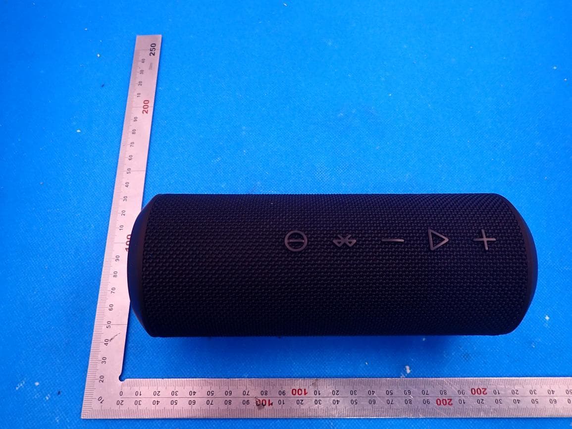
2AUEW-ZK606PRO
Jul 29, 2021Wireless Stereo Speaker
Equipment Class
DSS - Part 15 Spread Spectrum Transmitter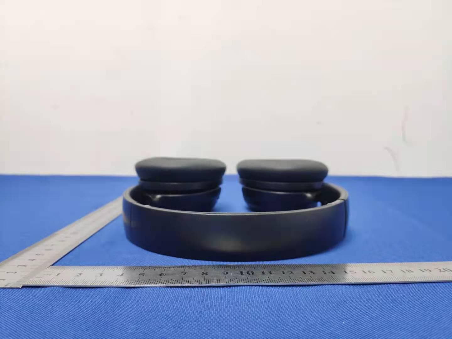
2AUEW-ZH700
Mar 14, 2021WIRELESS HEADPHONES
Equipment Class
DSS - Part 15 Spread Spectrum Transmitter